2010 JAGUAR XFR width
[x] Cancel search: widthPage 2058 of 3039
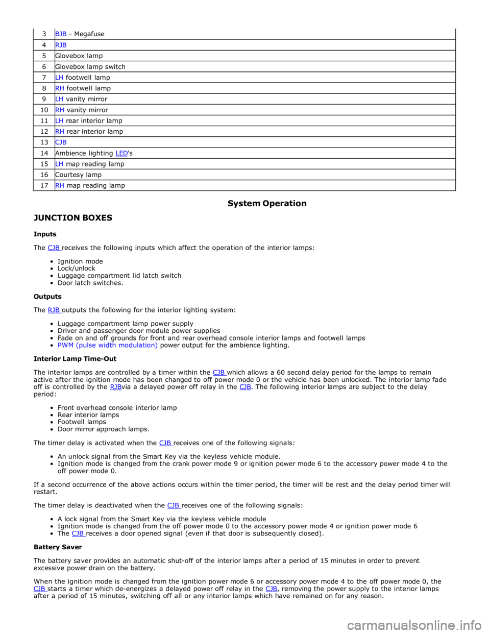
3 BJB - Megafuse 4 RJB 5 Glovebox lamp 6 Glovebox lamp switch 7 LH footwell lamp 8 RH footwell lamp 9 LH vanity mirror 10 RH vanity mirror 11 LH rear interior lamp 12 RH rear interior lamp 13 CJB 14 Ambience lighting LED's 15 LH map reading lamp 16 Courtesy lamp 17 RH map reading lamp
JUNCTION BOXES
Inputs System Operation
The CJB receives the following inputs which affect the operation of the interior lamps: Ignition mode
Lock/unlock
Luggage compartment lid latch switch
Door latch switches.
Outputs
The RJB outputs the following for the interior lighting system: Luggage compartment lamp power supply
Driver and passenger door module power supplies
Fade on and off grounds for front and rear overhead console interior lamps and footwell lamps
PWM (pulse width modulation) power output for the ambience lighting.
Interior Lamp Time-Out
The interior lamps are controlled by a timer within the CJB which allows a 60 second delay period for the lamps to remain active after the ignition mode has been changed to off power mode 0 or the vehicle has been unlocked. The interior lamp fade
off is controlled by the RJBvia a delayed power off relay in the CJB. The following interior lamps are subject to the delay period:
Front overhead console interior lamp
Rear interior lamps
Footwell lamps
Door mirror approach lamps.
The timer delay is activated when the CJB receives one of the following signals: An unlock signal from the Smart Key via the keyless vehicle module.
Ignition mode is changed from the crank power mode 9 or ignition power mode 6 to the accessory power mode 4 to the
off power mode 0.
If a second occurrence of the above actions occurs within the timer period, the timer will be rest and the delay period timer will
restart.
The timer delay is deactivated when the CJB receives one of the following signals: A lock signal from the Smart Key via the keyless vehicle module
Ignition mode is changed from the off power mode 0 to the accessory power mode 4 or ignition power mode 6
The CJB receives a door opened signal (even if that door is subsequently closed). Battery Saver
The battery saver provides an automatic shut-off of the interior lamps after a period of 15 minutes in order to prevent
excessive power drain on the battery.
When the ignition mode is changed from the ignition power mode 6 or accessory power mode 4 to the off power mode 0, the
CJB starts a timer which de-energizes a delayed power off relay in the CJB, removing the power supply to the interior lamps after a period of 15 minutes, switching off all or any interior lamps which have remained on for any reason.
Page 2295 of 3039
On vehicles installed with a driver's power operated memory seat and memory exterior mirrors, a potentiometer is incorporated
within each mirror motor and is used to provide information regarding the actual motor positions. The current position and
memory positions of each door mirror motor are maintained and stored within the corresponding door control module.
The memory exterior mirror positions are also monitored and stored within door control module memory when the reverse gear
mirror dip function is used.
When reverse gear is selected, the door control module stores the current mirror positions and will then dip the passenger
mirror glass to a default dip position. While reverse gear is selected it is possible to store a preferred dipped mirror position by
adjusting the driver/passenger mirror glass to the desired position via the mirror switch pack. When the desired position is
achieved using the switch, the new dip positions will be automatically stored by the door control module when reverse gear is
de-selected. Therefore when reverse gear is re-selected, the dip position recalled by the door control module will be the new
reverse gear mirror dip stored position. When reverse gear is deselected the mirror glass will automatically move to the previous
stored position prior to reverse gear selection.
If the driver selects a memory recall function using the memory seat switch pack, the driver's memory seat and exterior
memory mirrors are moved to a stored memory position.
Exterior mirrors with the power fold/auto fold feature incorporate a motor located in the hinge of each exterior mirror arm.
Operation of the power fold feature is achieved using the exterior mirror switch pack. Operation of the auto fold feature is
achieved using the remote handset.
The power fold function is active when the ignition is in power mode 6 (Ignition).
Both exterior mirrors will power fold when the mirror switch pack 'L' and 'R' switches are pressed together. Pressing the
switches again will unfold the mirrors.
When the instrument cluster is configured for the auto fold feature, the mirrors will fold in when the remote handset lock
button is pressed. The mirrors will unfold when the vehicle is unlocked using the remote handset unlock button.
NOTE: If the mirrors are folded in using the mirror switch pack (power fold) and the vehicle is then locked, subsequent
unlocking of the vehicle will not unfold the mirrors.
When the remote handset unlock button is operated, the CJB recognizes the remote handset for that vehicle and acknowledges the request. The door control modules are connected directly to the AJB (auxiliary junction box) for power supply to the
exterior mirror folding motors.
When the vehicle is locked the door control modules reverse the polarity of the mirror fold motor, power and ground
connections to operate the mirrors in the opposite direction.
Exterior mirror heating is provided with heater elements bonded to the back of the mirror glass. Power supply for the mirror
heating elements is provided by the corresponding driver or passenger door control module via the RJB. The door control modules receive a power supply from the RJB, and are both connected on the medium speed CAN bus to the ATC (automatic temperature control) module. A ground terminal from each door control module completes the circuit. The ATC module automatically controls the mirror heating function whenever the ignition is in power mode 4 (Accessory) and power mode 6
(Ignition).
Operation of the exterior mirror heaters is fully automatic and not controllable by the driver. Exterior mirror heater operation is
determined by ambient air temperature and windshield wiper status. When ambient air temperature reaches a pre-determined
level, the ATC module broadcasts an exterior mirror heating request to the door modules over the medium speed CAN bus. On receipt of this message, the door modules provide feed and ground connections to both exterior mirror heater elements.
The mirror heating is controlled in two phases, the initial heating phase and a second PWM (pulse width modulation) controlled
phase. In the first phase the heater elements in the mirrors are permanently powered for a pre-determined length of time. This
length of time varies with the ambient temperature. During the second PWM phase, the heater elements are turned on and off every 30 seconds. The amount of time the exterior mirror heaters are operational increases if the windshield wipers are
switched on. This ensures the mirrors remain mist free in damp and wet conditions, where there is an increased risk of misting.
Page 2708 of 3039
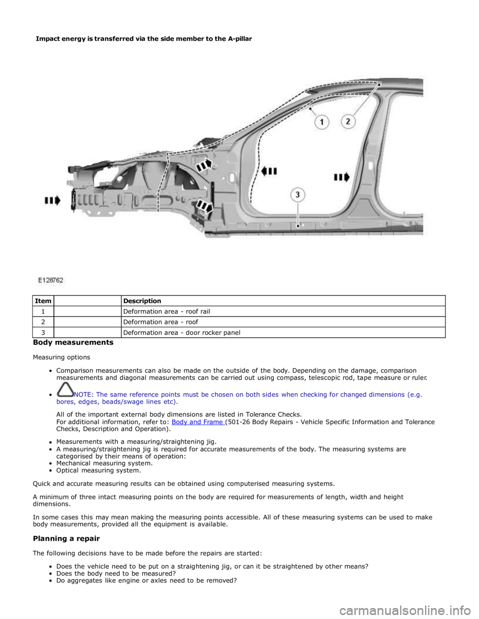
Item
Description 1
Deformation area - roof rail 2
Deformation area - roof 3
Deformation area - door rocker panel Body measurements
Measuring options
Comparison measurements can also be made on the outside of the body. Depending on the damage, comparison
measurements and diagonal measurements can be carried out using compass, telescopic rod, tape measure or ruler.
NOTE: The same reference points must be chosen on both sides when checking for changed dimensions (e.g.
bores, edges, beads/swage lines etc).
All of the important external body dimensions are listed in Tolerance Checks.
For additional information, refer to: Body and Frame (501-26 Body Repairs - Vehicle Specific Information and Tolerance Checks, Description and Operation).
Measurements with a measuring/straightening jig.
A measuring/straightening jig is required for accurate measurements of the body. The measuring systems are
categorised by their means of operation:
Mechanical measuring system.
Optical measuring system.
Quick and accurate measuring results can be obtained using computerised measuring systems.
A minimum of three intact measuring points on the body are required for measurements of length, width and height
dimensions.
In some cases this may mean making the measuring points accessible. All of these measuring systems can be used to make
body measurements, provided all the equipment is available.
Planning a repair
The following decisions have to be made before the repairs are started:
Does the vehicle need to be put on a straightening jig, or can it be straightened by other means?
Does the body need to be measured?
Do aggregates like engine or axles need to be removed? Impact energy is transferred via the side member to the A-pillar
Page 2719 of 3039
Apply polyester filler (only onto bare metal).
Apply filler.
Lightly sand the whole component.
Thoroughly clean with silicone remover and rub dry.
Apply corrosion protection primer to bare areas.
The clinched flanges on the hood, doors, tailgate and liftgate must be sealed with clinched flange sealer, if this is not already
applied.
Weld Components
Use a stripping disc to remove the cathodic primer on the inside and outside of the area to be welded. The stripped area
should be kept as small as possible, retaining as much of the cathodic primer as possible, taking care not to damage the zinc
coating.
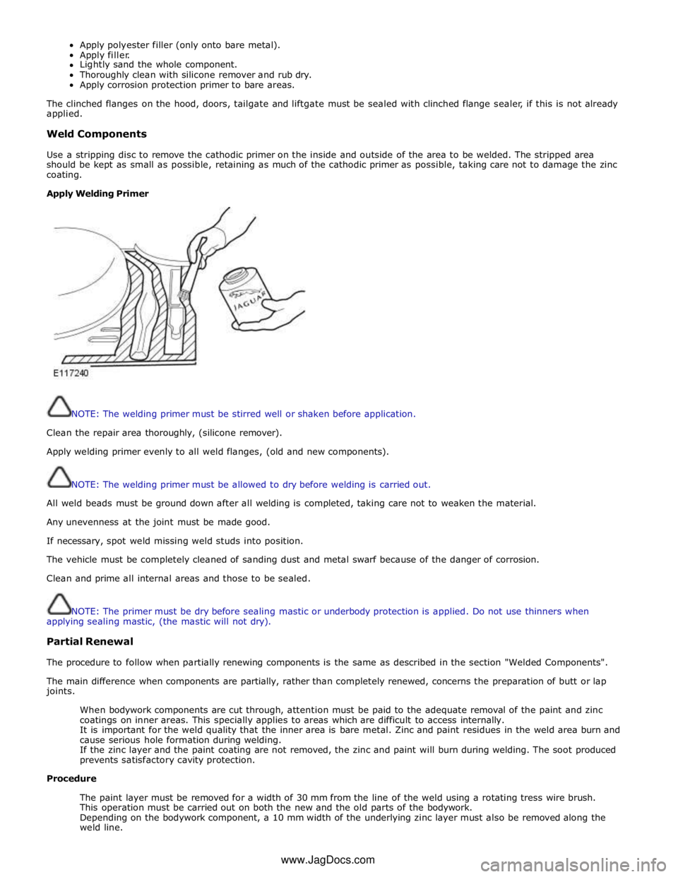
Apply Welding Primer
NOTE: The welding primer must be stirred well or shaken before application.
Clean the repair area thoroughly, (silicone remover).
Apply welding primer evenly to all weld flanges, (old and new components).
NOTE: The welding primer must be allowed to dry before welding is carried out.
All weld beads must be ground down after all welding is completed, taking care not to weaken the material.
Any unevenness at the joint must be made good.
If necessary, spot weld missing weld studs into position.
The vehicle must be completely cleaned of sanding dust and metal swarf because of the danger of corrosion.
Clean and prime all internal areas and those to be sealed.
NOTE: The primer must be dry before sealing mastic or underbody protection is applied. Do not use thinners when
applying sealing mastic, (the mastic will not dry).
Partial Renewal
The procedure to follow when partially renewing components is the same as described in the section "Welded Components".
The main difference when components are partially, rather than completely renewed, concerns the preparation of butt or lap
joints.
When bodywork components are cut through, attention must be paid to the adequate removal of the paint and zinc
coatings on inner areas. This specially applies to areas which are difficult to access internally.
It is important for the weld quality that the inner area is bare metal. Zinc and paint residues in the weld area burn and
cause serious hole formation during welding.
If the zinc layer and the paint coating are not removed, the zinc and paint will burn during welding. The soot produced
prevents satisfactory cavity protection.
Procedure
The paint layer must be removed for a width of 30 mm from the line of the weld using a rotating tress wire brush.
This operation must be carried out on both the new and the old parts of the bodywork.
Depending on the bodywork component, a 10 mm width of the underlying zinc layer must also be removed along the
weld line. www.JagDocs.com
Page 2732 of 3039
Part N-umber
Body Repairs - Water Leaks - Water Leaks
Description and Operation
General Published: 11-May-2011
If water leaks occur after bodywork repairs, the cause can be established using the checks described below. A
systematic and logical procedure is required to locate water leaks. Before beginning extensive checks, a thorough visual
inspection must be carried out.
Visual Inspection
- The following characteristics may indicate existing leaks:
- Check the clearance and accurate fit of ancillary components such as the hood, tailgate, liftgate, doors, and so
on.
- Check for correct fit and possible damage to sealing elements such as blanking plugs, rubber door seals, and so
on.
- Check water drain holes for unhindered flow.
Various tests can be used to provide further information on possible leaks:
- Water test
- Washer test
- Road test
- Chalk (powder) test
Practical execution of tests and checks
Water test
NOTE: Never aim a jet of water directly at a rubber seal.
Carry out the water test with a second person present (in the passenger compartment).
Use variable washer nozzles (concentrated water jet to fine spray mist).
Start in the lower section and spray the whole area, working upwards in stages.
Washer test
Further tests can be carried out in the washer system.
Some leaks originate here, or only occur here.
The relevant passenger compartment should be checked using a torch during the wash procedure.
Road test
If no leaks are located during the tests above, road tests should be carried out on wet roads.
Road tests under various conditions:
- At various speeds.
- On various road surfaces (asphalt to cobbles).
- With loaded or unloaded vehicle.
- Driving through puddles (splash water).
Chalk test (powder test)
In this test, the clamping load and the bearing surface of the seal are checked.
Performing the test:
- Dust the door seal with powder or coat with chalk.
- Coat the bearing surface of the seal with a thin film of Vaseline.
- Slowly close the door and open it again.
- Check the width and continuity of the imprint on the door seal.
Other test equipment
Other equipment such as stethoscopes, UV lamps, special mirrors or ultrasound measuring instruments can be used to
locate leaks.
Rectifying the leak using recommended tools, auxiliary equipment and materials
Tools and auxiliary equipment:
- Dry, absorbent cloths
- Variable washer nozzle
- Torch, fluorescent tube
- Mirror
- Compressed air
- Seal lip installer
- Wet/dry vacuum cleaner
- Sealing compound compressor
- Remover for interior trim
- Cutter blade or pocket knife
- Wedge (wood or plastic)
- Hot air blower
- Special mirror for concealed leaks
Page 2987 of 3039
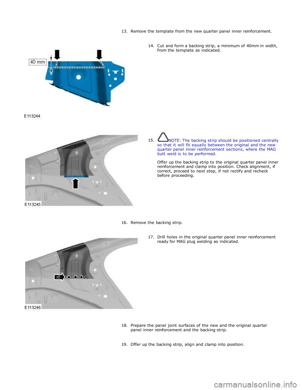
13. Remove the template from the new quarter panel inner reinforcement.
14.
15. Cut and form a backing strip, a minimum of 40mm in width,
from the template as indicated.
NOTE: The backing strip should be positioned centrally
so that it will fit equally between the original and the new
quarter panel inner reinforcement sections, where the MAG
butt weld is to be performed.
Offer up the backing strip to the original quarter panel inner
reinforcement and clamp into position. Check alignment, if
correct, proceed to next step, if not rectify and recheck
before proceeding.
16. Remove the backing strip.
17. Drill holes in the original quarter panel inner reinforcement
ready for MAG plug welding as indicated.
18. Prepare the panel joint surfaces of the new and the original quarter
panel inner reinforcement and the backing strip.
19. Offer up the backing strip, align and clamp into position.