2010 JAGUAR XFR width
[x] Cancel search: widthPage 1428 of 3039
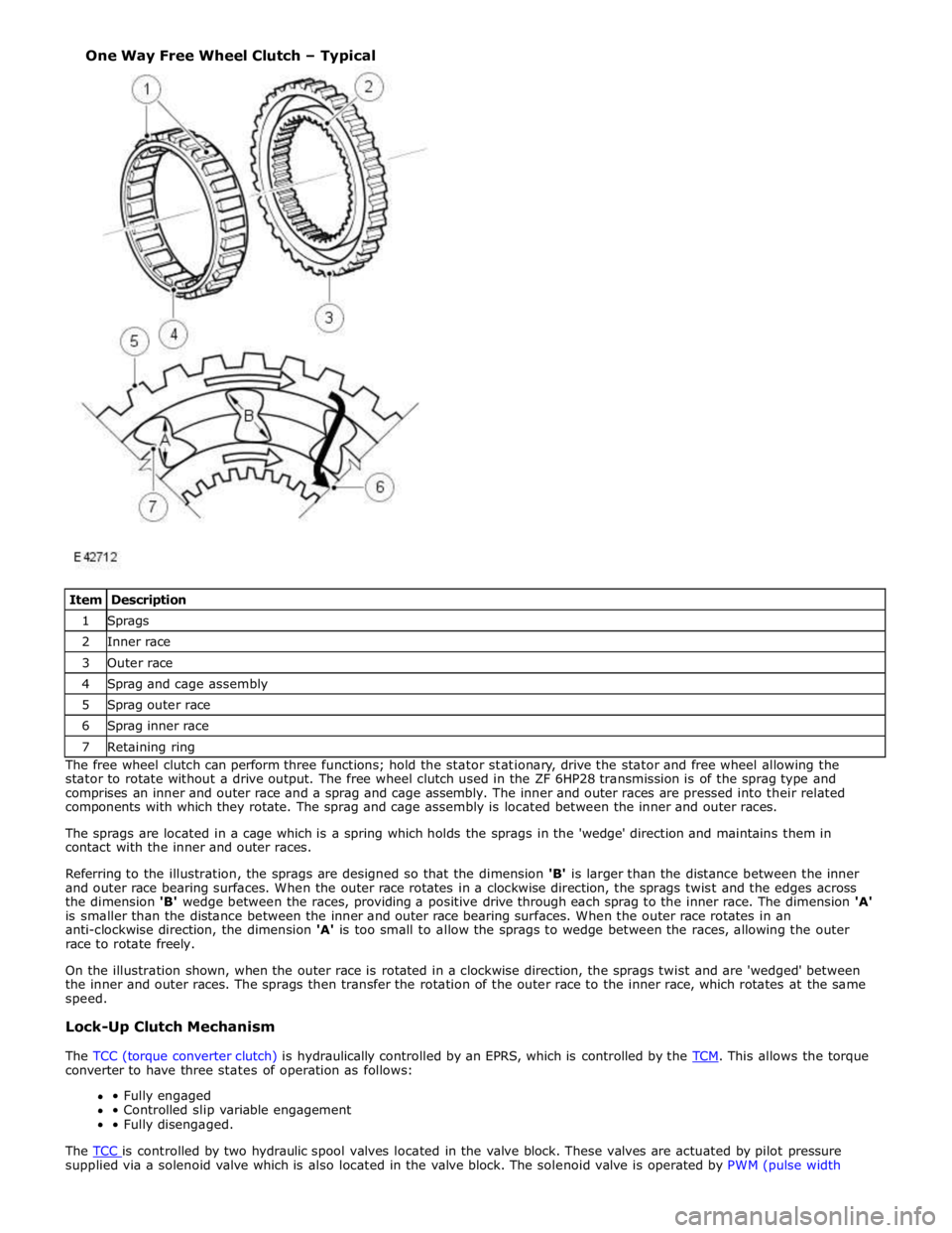
1 Sprags 2 Inner race 3 Outer race 4 Sprag and cage assembly 5 Sprag outer race 6 Sprag inner race 7 Retaining ring The free wheel clutch can perform three functions; hold the stator stationary, drive the stator and free wheel allowing the
stator to rotate without a drive output. The free wheel clutch used in the ZF 6HP28 transmission is of the sprag type and
comprises an inner and outer race and a sprag and cage assembly. The inner and outer races are pressed into their related
components with which they rotate. The sprag and cage assembly is located between the inner and outer races.
The sprags are located in a cage which is a spring which holds the sprags in the 'wedge' direction and maintains them in
contact with the inner and outer races.
Referring to the illustration, the sprags are designed so that the dimension 'B' is larger than the distance between the inner
and outer race bearing surfaces. When the outer race rotates in a clockwise direction, the sprags twist and the edges across
the dimension 'B' wedge between the races, providing a positive drive through each sprag to the inner race. The dimension 'A'
is smaller than the distance between the inner and outer race bearing surfaces. When the outer race rotates in an
anti-clockwise direction, the dimension 'A' is too small to allow the sprags to wedge between the races, allowing the outer
race to rotate freely.
On the illustration shown, when the outer race is rotated in a clockwise direction, the sprags twist and are 'wedged' between
the inner and outer races. The sprags then transfer the rotation of the outer race to the inner race, which rotates at the same
speed.
Lock-Up Clutch Mechanism
The TCC (torque converter clutch) is hydraulically controlled by an EPRS, which is controlled by the TCM. This allows the torque converter to have three states of operation as follows:
• Fully engaged
• Controlled slip variable engagement
• Fully disengaged.
The TCC is controlled by two hydraulic spool valves located in the valve block. These valves are actuated by pilot pressure supplied via a solenoid valve which is also located in the valve block. The solenoid valve is operated by PWM (pulse width One Way Free Wheel Clutch – Typical
Page 1584 of 3039

the flow and pressure supplied by controlling the operation of the fuel pump using a PWM (pulse width modulation) output. A
LP sensor is located in the fuel feed supply line to the engine and is monitored by the ECM for fuel pump control.
Two fuel level sensors are installed in either side of the saddle tank. The sensors are a MAPPS (magnetic passive position
sensor) which provide a variable resistance to ground for the output from the fuel gage.
The fuel system also incorporates an EVAP (evaporative emission) system which is part of the on-board refueling and vapor
recovery feature. The function and operation of the system is designed to meet EVAP requirements to minimize fuel vapor losses.
Page 1589 of 3039
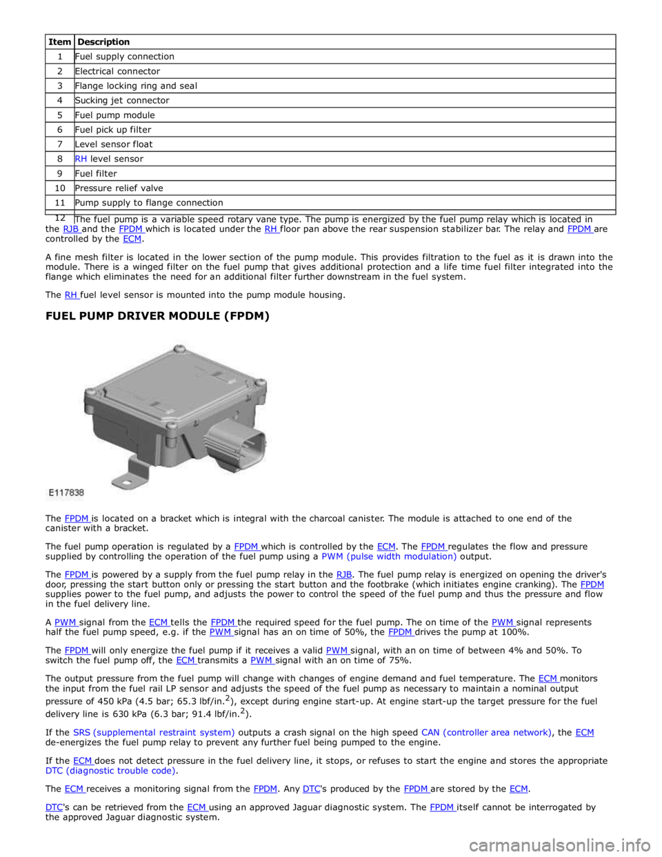
1 Fuel supply connection 2 Electrical connector 3 Flange locking ring and seal 4 Sucking jet connector 5 Fuel pump module 6 Fuel pick up filter 7 Level sensor float 8 RH level sensor 9 Fuel filter 10 Pressure relief valve 11 Pump supply to flange connection 12 The fuel pump is a variable speed rotary vane type. The pump is energized by the fuel pump relay which is located in the RJB and the FPDM which is located under the RH floor pan above the rear suspension stabilizer bar. The relay and FPDM are controlled by the ECM.
A fine mesh filter is located in the lower section of the pump module. This provides filtration to the fuel as it is drawn into the
module. There is a winged filter on the fuel pump that gives additional protection and a life time fuel filter integrated into the
flange which eliminates the need for an additional filter further downstream in the fuel system.
The RH fuel level sensor is mounted into the pump module housing.
FUEL PUMP DRIVER MODULE (FPDM)
The FPDM is located on a bracket which is integral with the charcoal canister. The module is attached to one end of the canister with a bracket.
The fuel pump operation is regulated by a FPDM which is controlled by the ECM. The FPDM regulates the flow and pressure supplied by controlling the operation of the fuel pump using a PWM (pulse width modulation) output.
The FPDM is powered by a supply from the fuel pump relay in the RJB. The fuel pump relay is energized on opening the driver's door, pressing the start button only or pressing the start button and the footbrake (which initiates engine cranking). The FPDM supplies power to the fuel pump, and adjusts the power to control the speed of the fuel pump and thus the pressure and flow
in the fuel delivery line.
A PWM signal from the ECM tells the FPDM the required speed for the fuel pump. The on time of the PWM signal represents half the fuel pump speed, e.g. if the PWM signal has an on time of 50%, the FPDM drives the pump at 100%.
The FPDM will only energize the fuel pump if it receives a valid PWM signal, with an on time of between 4% and 50%. To switch the fuel pump off, the ECM transmits a PWM signal with an on time of 75%.
The output pressure from the fuel pump will change with changes of engine demand and fuel temperature. The ECM monitors the input from the fuel rail LP sensor and adjusts the speed of the fuel pump as necessary to maintain a nominal output
pressure of 450 kPa (4.5 bar; 65.3 lbf/in.2
), except during engine start-up. At engine start-up the target pressure for the fuel
delivery line is 630 kPa (6.3 bar; 91.4 lbf/in.2
).
If the SRS (supplemental restraint system) outputs a crash signal on the high speed CAN (controller area network), the ECM de-energizes the fuel pump relay to prevent any further fuel being pumped to the engine.
If the ECM does not detect pressure in the fuel delivery line, it stops, or refuses to start the engine and stores the appropriate DTC (diagnostic trouble code).
The ECM receives a monitoring signal from the FPDM. Any DTC's produced by the FPDM are stored by the ECM.
DTC's can be retrieved from the ECM using an approved Jaguar diagnostic system. The FPDM itself cannot be interrogated by the approved Jaguar diagnostic system.
Page 1641 of 3039
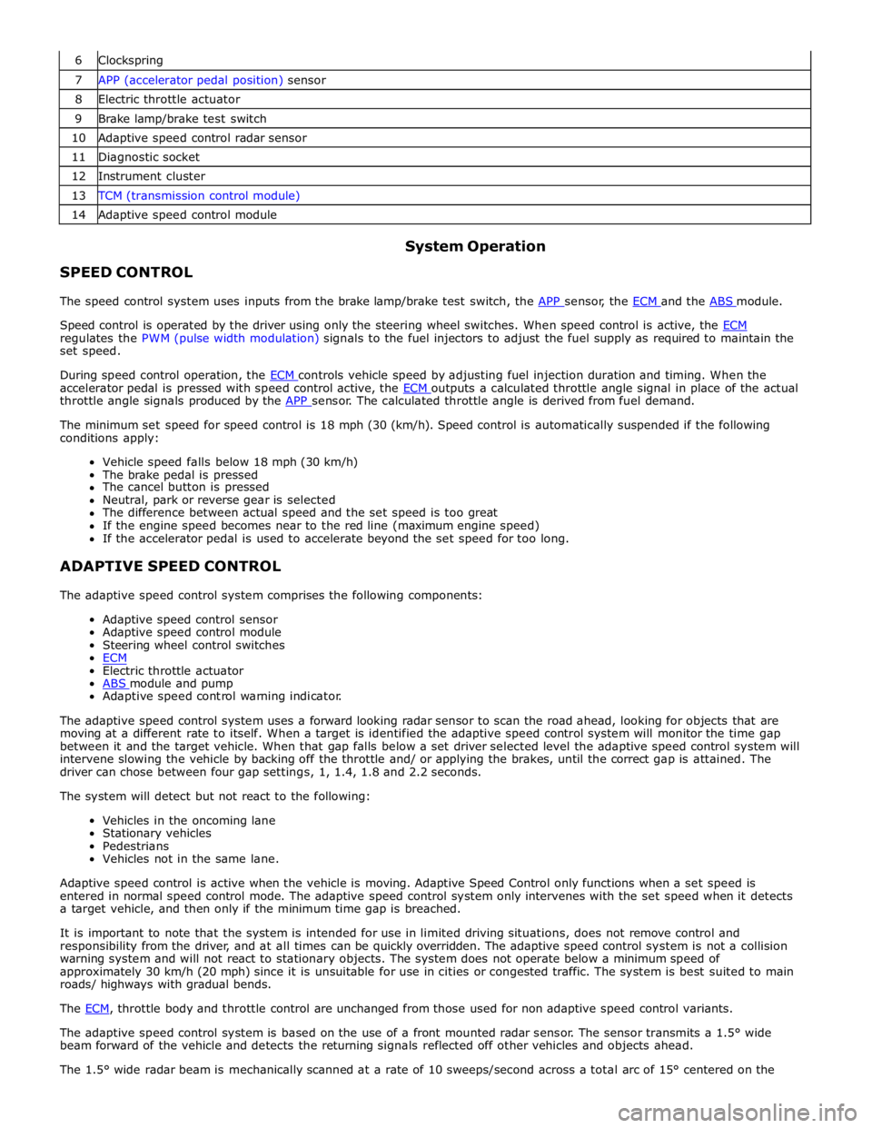
6 Clockspring 7 APP (accelerator pedal position) sensor 8 Electric throttle actuator 9 Brake lamp/brake test switch 10 Adaptive speed control radar sensor 11 Diagnostic socket 12 Instrument cluster 13 TCM (transmission control module) 14 Adaptive speed control module
SPEED CONTROL System Operation
The speed control system uses inputs from the brake lamp/brake test switch, the APP sensor, the ECM and the ABS module.
Speed control is operated by the driver using only the steering wheel switches. When speed control is active, the ECM regulates the PWM (pulse width modulation) signals to the fuel injectors to adjust the fuel supply as required to maintain the
set speed.
During speed control operation, the ECM controls vehicle speed by adjusting fuel injection duration and timing. When the accelerator pedal is pressed with speed control active, the ECM outputs a calculated throttle angle signal in place of the actual throttle angle signals produced by the APP sensor. The calculated throttle angle is derived from fuel demand.
The minimum set speed for speed control is 18 mph (30 (km/h). Speed control is automatically suspended if the following
conditions apply:
Vehicle speed falls below 18 mph (30 km/h)
The brake pedal is pressed
The cancel button is pressed
Neutral, park or reverse gear is selected
The difference between actual speed and the set speed is too great
If the engine speed becomes near to the red line (maximum engine speed)
If the accelerator pedal is used to accelerate beyond the set speed for too long.
ADAPTIVE SPEED CONTROL
The adaptive speed control system comprises the following components:
Adaptive speed control sensor
Adaptive speed control module
Steering wheel control switches
ECM
Electric throttle actuator
ABS module and pump Adaptive speed control warning indicator.
The adaptive speed control system uses a forward looking radar sensor to scan the road ahead, looking for objects that are
moving at a different rate to itself. When a target is identified the adaptive speed control system will monitor the time gap
between it and the target vehicle. When that gap falls below a set driver selected level the adaptive speed control system will
intervene slowing the vehicle by backing off the throttle and/ or applying the brakes, until the correct gap is attained. The
driver can chose between four gap settings, 1, 1.4, 1.8 and 2.2 seconds.
The system will detect but not react to the following:
Vehicles in the oncoming lane
Stationary vehicles
Pedestrians
Vehicles not in the same lane.
Adaptive speed control is active when the vehicle is moving. Adaptive Speed Control only functions when a set speed is
entered in normal speed control mode. The adaptive speed control system only intervenes with the set speed when it detects
a target vehicle, and then only if the minimum time gap is breached.
It is important to note that the system is intended for use in limited driving situations, does not remove control and
responsibility from the driver, and at all times can be quickly overridden. The adaptive speed control system is not a collision
warning system and will not react to stationary objects. The system does not operate below a minimum speed of
approximately 30 km/h (20 mph) since it is unsuitable for use in cities or congested traffic. The system is best suited to main
roads/ highways with gradual bends.
The ECM, throttle body and throttle control are unchanged from those used for non adaptive speed control variants.
The adaptive speed control system is based on the use of a front mounted radar sensor. The sensor transmits a 1.5° wide
beam forward of the vehicle and detects the returning signals reflected off other vehicles and objects ahead.
The 1.5° wide radar beam is mechanically scanned at a rate of 10 sweeps/second across a total arc of 15° centered on the
Page 1693 of 3039
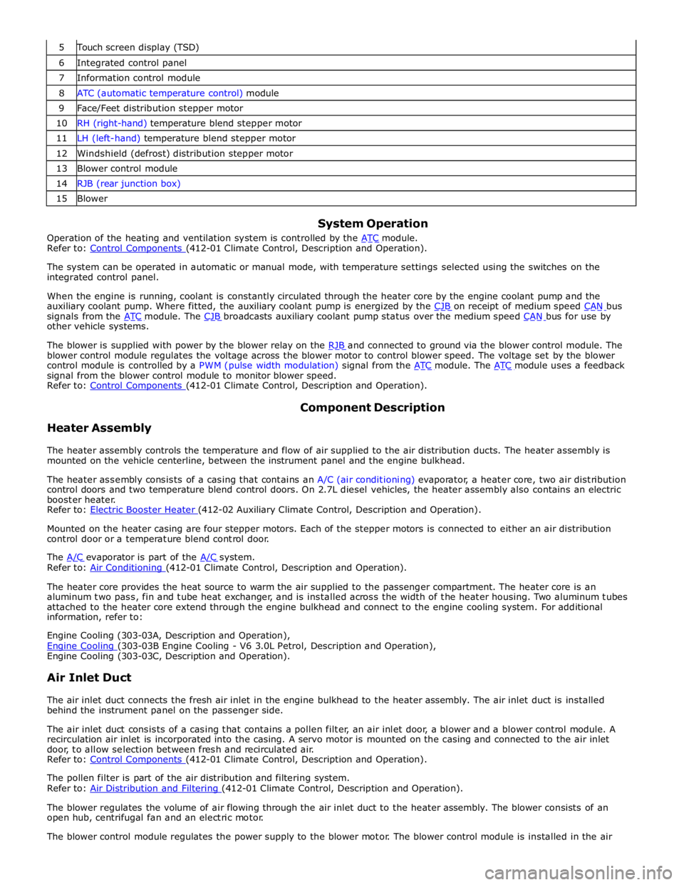
Touch screen display (TSD) 6 Integrated control panel 7 Information control module 8 ATC (automatic temperature control) module 9 Face/Feet distribution stepper motor 10 RH (right-hand) temperature blend stepper motor 11 LH (left-hand) temperature blend stepper motor 12 Windshield (defrost) distribution stepper motor 13 Blower control module 14 RJB (rear junction box) 15 Blower
System Operation
Operation of the heating and ventilation system is controlled by the ATC module. Refer to: Control Components (412-01 Climate Control, Description and Operation).
The system can be operated in automatic or manual mode, with temperature settings selected using the switches on the
integrated control panel.
When the engine is running, coolant is constantly circulated through the heater core by the engine coolant pump and the
auxiliary coolant pump. Where fitted, the auxiliary coolant pump is energized by the CJB on receipt of medium speed CAN bus signals from the ATC module. The CJB broadcasts auxiliary coolant pump status over the medium speed CAN bus for use by other vehicle systems.
The blower is supplied with power by the blower relay on the RJB and connected to ground via the blower control module. The blower control module regulates the voltage across the blower motor to control blower speed. The voltage set by the blower
control module is controlled by a PWM (pulse width modulation) signal from the ATC module. The ATC module uses a feedback signal from the blower control module to monitor blower speed.
Refer to: Control Components (412-01 Climate Control, Description and Operation).
Heater Assembly Component Description
The heater assembly controls the temperature and flow of air supplied to the air distribution ducts. The heater assembly is
mounted on the vehicle centerline, between the instrument panel and the engine bulkhead.
The heater assembly consists of a casing that contains an A/C (air conditioning) evaporator, a heater core, two air distribution
control doors and two temperature blend control doors. On 2.7L diesel vehicles, the heater assembly also contains an electric
booster heater.
Refer to: Electric Booster Heater (412-02 Auxiliary Climate Control, Description and Operation).
Mounted on the heater casing are four stepper motors. Each of the stepper motors is connected to either an air distribution
control door or a temperature blend control door.
The A/C evaporator is part of the A/C system. Refer to: Air Conditioning (412-01 Climate Control, Description and Operation).
The heater core provides the heat source to warm the air supplied to the passenger compartment. The heater core is an
aluminum two pass, fin and tube heat exchanger, and is installed across the width of the heater housing. Two aluminum tubes
attached to the heater core extend through the engine bulkhead and connect to the engine cooling system. For additional
information, refer to:
Engine Cooling (303-03A, Description and Operation),
Engine Cooling (303-03B Engine Cooling - V6 3.0L Petrol, Description and Operation), Engine Cooling (303-03C, Description and Operation).
Air Inlet Duct
The air inlet duct connects the fresh air inlet in the engine bulkhead to the heater assembly. The air inlet duct is installed
behind the instrument panel on the passenger side.
The air inlet duct consists of a casing that contains a pollen filter, an air inlet door, a blower and a blower control module. A
recirculation air inlet is incorporated into the casing. A servo motor is mounted on the casing and connected to the air inlet
door, to allow selection between fresh and recirculated air.
Refer to: Control Components (412-01 Climate Control, Description and Operation). The pollen filter is part of the air distribution and filtering system.
Refer to: Air Distribution and Filtering (412-01 Climate Control, Description and Operation).
The blower regulates the volume of air flowing through the air inlet duct to the heater assembly. The blower consists of an
open hub, centrifugal fan and an electric motor.
The blower control module regulates the power supply to the blower motor. The blower control module is installed in the air
Page 1834 of 3039
Blind Spot Monitoring System Operation
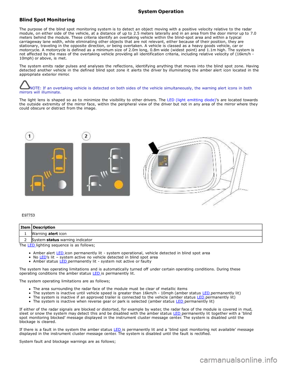
The purpose of the blind spot monitoring system is to detect an object moving with a positive velocity relative to the radar
module, on either side of the vehicle, at a distance of up to 2.5 meters laterally and in an area from the door mirror up to 7.0
meters behind the module. These criteria identify an overtaking vehicle within the blind-spot area and within a typical
carriageway lane width, while eliminating other objects that are not relevant, either because of their position, they are
stationary, traveling in the opposite direction, or being overtaken. A vehicle is classed as a heavy goods vehicle, car or
motorcycle. A motorcycle is defined as a minimum size of 2.0m long, 0.8m wide (widest point) and 1.1m high. The system is
not affected by the mass of the overtaking vehicle providing all identification criteria, including relative velocity of (16km/h -
10mph) or above, is met.
The system emits radar pulses and analyses the reflections, identifying anything that moves into the blind spot zone. Having
detected another vehicle in the defined blind spot zone it alerts the driver by illuminating the amber alert icon located in the
appropriate exterior mirror.
NOTE: If an overtaking vehicle is detected on both sides of the vehicle simultaneously, the warning alert icons in both
mirrors will illuminate.
The light lens is shaped so as to minimize the visibility to other drivers. The LED (light emitting diode)’s are located towards
the outside extremity of the mirror face, within the peripheral view of the driver but not in any area of the mirror where they
could obscure or distract from the image.
Item Description 1 Warning alert icon 2 System status warning indicator The LED lighting sequence is as follows;
Amber alert LED icon permanently lit - system operational, vehicle detected in blind spot area No LED’s lit – system active no vehicle detected in blind spot area Amber status LED permanently lit - system not active or faulty
The system has operating limitations and is automatically turned off under certain operating conditions. During these
operating conditions the amber status LED is permanently lit. The system operating limitations are as follows;
The area surrounding the radar face of the module must be clear of metallic items
The system is inactive until vehicle speed is greater than 16km/h - 10mph (amber status LED permanently lit) The system is inactive if an approved trailer is connected to the vehicle (amber status LED permanently lit) The system is inactive when reverse gear or park is selected (amber status LED permanently lit)
If either of the radar signals are blocked or distorted, for example by water, the radar face of the module is covered in mud,
sleet or snow the system may detect this and be disabled with the amber status LED permanently lit together with a ‘blind spot monitoring blocked’ message displayed in the instrument cluster message center. The system is disabled until the
blockage is cleared.
If there is a fault in the system the amber status LED is permanently lit and a ‘blind spot monitoring not available’ message displayed in the instrument cluster message center. The system is disabled until the fault is rectified.
System fault and blockage warnings are as follows;
Page 1849 of 3039
PARKING AID CAMERA
The parking aid camera receives an ignition power mode 6 power supply from the RJB. It also has a LIN bus connection with the RJB, which is used as a gateway. A shielded co-axial cable connection between the camera and the TSD is used for the video image transmission.
The camera receives power at all times when the ignition is in power mode 6. When reverse gear is selected, the RJB transmits a reverse selected message on the medium speed CAN bus. The information and entertainment module transfers the message on the MOST ring to the TSD, which displays the video input from the parking aid camera in preference to the parking
aid alert screen.
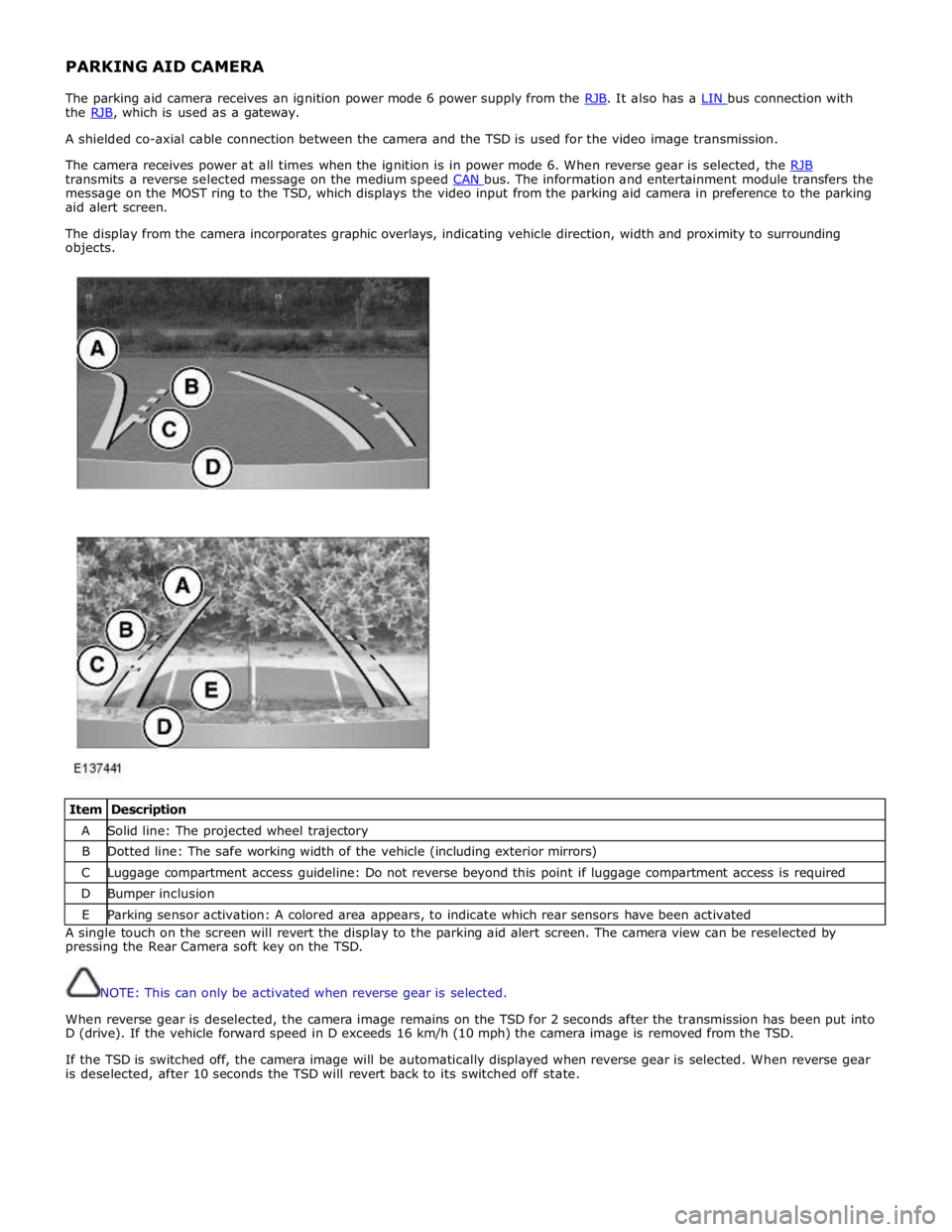
The display from the camera incorporates graphic overlays, indicating vehicle direction, width and proximity to surrounding
objects.
Item Description A Solid line: The projected wheel trajectory B Dotted line: The safe working width of the vehicle (including exterior mirrors) C Luggage compartment access guideline: Do not reverse beyond this point if luggage compartment access is required D Bumper inclusion E Parking sensor activation: A colored area appears, to indicate which rear sensors have been activated A single touch on the screen will revert the display to the parking aid alert screen. The camera view can be reselected by
pressing the Rear Camera soft key on the TSD.
NOTE: This can only be activated when reverse gear is selected.
When reverse gear is deselected, the camera image remains on the TSD for 2 seconds after the transmission has been put into
D (drive). If the vehicle forward speed in D exceeds 16 km/h (10 mph) the camera image is removed from the TSD.
If the TSD is switched off, the camera image will be automatically displayed when reverse gear is selected. When reverse gear
is deselected, after 10 seconds the TSD will revert back to its switched off state.
Page 2033 of 3039
Halogen Low/high Beam Headlamp
The halogen low/high beam headlamp uses a projector lens, similar to the xenon headlamp. The projector module comprises
an ellipsoidal lens and a reflector. The projector reflector collects the light produced by the halogen bulb and projects the light
into a focal plane containing a shield. The contour of the shield is projected onto the road by the lens. The low/high beam
bulbs are quartz halogen and are retained in the headlamp unit with conventional wire retaining clips.
A tourist lever mechanism is located on the right hand side of the projector module. This mechanism moves a flap to blank off
a portion of the beam spread to enable the vehicle to be driven in opposite drive hand markets without applying blanking
decals to the headlamp lens. The beam is changed by removing the access cover at the rear of the lamp assembly and moving
a small lever located near the bulb holder, at the side of the projector.
Halogen High Beam Headlamp - Xenon and Halogen
The xenon and halogen headlamps use a complex surface reflector for the halogen fill in high beam lamp only lighting unit,
which is of the same design on both headlamp types. This type of reflector has the reflector divided into separate parabolic
segments, with each segment having a different focal length.
The high beam headlamp bulbs are quartz halogen and are retained in the headlamp unit with conventional wire retaining
clips.
Cornering Lamps
NOTE: The cornering lamps are not fitted to NAS vehicles.
The cornering lamps are an optional feature designed to illuminate the direction of travel when cornering at low speeds. The
design of the lens projects a spread of light from the vehicle at approximately 45 degrees to the vehicle axis. The cornering
lamp is incorporated into the headlamp assembly and shares the same housing as the low beam headlamp. The cornering lamp
uses a 35W Halogen H8 bulb which is permanently located in an integral holder which is connected on the headlamp housing.
The holder is located in an aperture in the headlamp housing and rotated to lock. The bulb is accessible via a removable cover
on the base of the headlamp housing.
The cornering lamps are controlled by the LH steering column multifunction switch with the lighting control switch in the headlamp position and the ignition in power mode 6. The cornering lamps are supplied power via the ignition circuit to ensure
that they do not function with the headlamp delay feature. The cornering lamps are deactivated if the vehicle speed exceeds
25 mph (40 km/h). Only one cornering lamp will illuminate at any one time. If the left hand turn signal indicators are selected
on, the left hand cornering lamp will be illuminated and vice versa, providing the vehicle speed and lighting control switch
positions are correct.
Static Bending Lamps
NOTE: The static bending lamps are not fitted to NAS vehicles.
The static bending lamps are designed to illuminate the direction of travel when cornering at low speeds. The static bending
lamp functionality, which is controlled by the CJB and the headlamp leveling module, operates using inputs from the steering angle sensor and vehicle speed information from the ABS (anti-lock brake system) module. The static bending lamp is
incorporated into the headlamp assembly and shares the same housing as the low beam headlamp. The design of the lens
projects a spread of light from the vehicle at approximately 45 degrees to the vehicle axis. The static bending lamp uses a
35W Halogen H8 bulb which locates in a holder which is connected via wires to the main connector on the headlamp housing.
The holder is located in an aperture in the headlamp housing and rotated to lock. The bulb is accessible via a removable cover
at the rear of the headlamp housing.
The static bending lamps operate with a steering angle sensor CAN bus signal which is received by the CJB. The CJB monitors this signal and vehicle speed and activates the static bending lamp bulb. When the operation parameters of the lamp are
reached, the CJB fades the static bending lamp bulb on using a PWM (pulse width modulation) voltage over a period of approximately 2 seconds. When the lamp is switched off, the CJB fades the bulb off by decreasing the PWM voltage in a linear manner depending on steering angle and vehicle speed. The cornering lamps can only be active for a maximum of 3 minutes.
NOTE: Static bending lamps only operate when the transmission is in DRIVE or in SPORT.
Turn Signal Indicators
The turn signal indicator lamp is incorporated into the outer part of the headlamp assembly. The turn signal indicator lamp
uses a PY21W bayonet orange colored bulb in ROW markets, a S8W 27/7W wedge bulb is used in NAS markets. The bulb is
fitted into a holder which connects with contacts in the headlamp housing. The holder is fitted into an aperture in the
headlamp housing and rotated to lock into position.
When active, the turn signal indicator lamps will flash at a frequency cycle of 380ms on and 380ms off. If a bulb fails, the
remaining turn signal lamps bulbs continue to flash at normal speed. The turn signal indicators in the instrument cluster will
flash at double speed to indicate the bulb failure to the driver.
Side Lamps
The side lamp is located between the headlamp projector module and the high bean headlamp. The side lamp uses a W5W
wedge fitting bulb which locates in a holder which connected via wires to the main connector on the headlamp housing. The
holder is a push fit into a receptacle in the headlamp housing. The bulb is accessible by removal of the inner cover on the rear
of the headlamp housing. Access to the bulb requires removal of the headlamp from the vehicle. The side lamps are operated
by selecting side lamps or headlamps on the lighting control switch. The side lamps are functional at all times and are