2010 JAGUAR XFR srs
[x] Cancel search: srsPage 1589 of 3039
1 Fuel supply connection 2 Electrical connector 3 Flange locking ring and seal 4 Sucking jet connector 5 Fuel pump module 6 Fuel pick up filter 7 Level sensor float 8 RH level sensor 9 Fuel filter 10 Pressure relief valve 11 Pump supply to flange connection 12 The fuel pump is a variable speed rotary vane type. The pump is energized by the fuel pump relay which is located in the RJB and the FPDM which is located under the RH floor pan above the rear suspension stabilizer bar. The relay and FPDM are controlled by the ECM.
A fine mesh filter is located in the lower section of the pump module. This provides filtration to the fuel as it is drawn into the
module. There is a winged filter on the fuel pump that gives additional protection and a life time fuel filter integrated into the
flange which eliminates the need for an additional filter further downstream in the fuel system.
The RH fuel level sensor is mounted into the pump module housing.
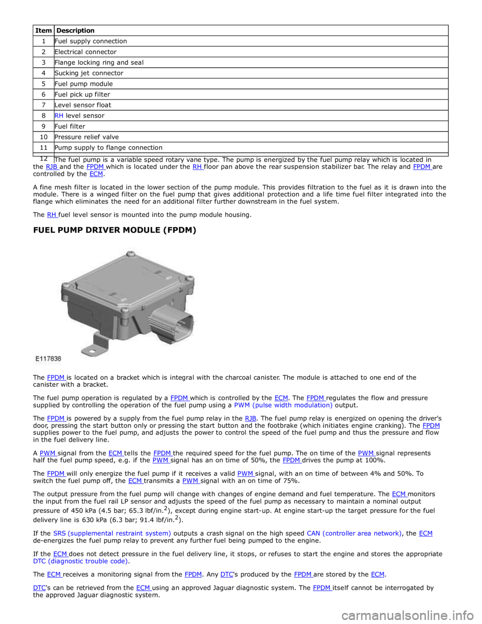
FUEL PUMP DRIVER MODULE (FPDM)
The FPDM is located on a bracket which is integral with the charcoal canister. The module is attached to one end of the canister with a bracket.
The fuel pump operation is regulated by a FPDM which is controlled by the ECM. The FPDM regulates the flow and pressure supplied by controlling the operation of the fuel pump using a PWM (pulse width modulation) output.
The FPDM is powered by a supply from the fuel pump relay in the RJB. The fuel pump relay is energized on opening the driver's door, pressing the start button only or pressing the start button and the footbrake (which initiates engine cranking). The FPDM supplies power to the fuel pump, and adjusts the power to control the speed of the fuel pump and thus the pressure and flow
in the fuel delivery line.
A PWM signal from the ECM tells the FPDM the required speed for the fuel pump. The on time of the PWM signal represents half the fuel pump speed, e.g. if the PWM signal has an on time of 50%, the FPDM drives the pump at 100%.
The FPDM will only energize the fuel pump if it receives a valid PWM signal, with an on time of between 4% and 50%. To switch the fuel pump off, the ECM transmits a PWM signal with an on time of 75%.
The output pressure from the fuel pump will change with changes of engine demand and fuel temperature. The ECM monitors the input from the fuel rail LP sensor and adjusts the speed of the fuel pump as necessary to maintain a nominal output
pressure of 450 kPa (4.5 bar; 65.3 lbf/in.2
), except during engine start-up. At engine start-up the target pressure for the fuel
delivery line is 630 kPa (6.3 bar; 91.4 lbf/in.2
).
If the SRS (supplemental restraint system) outputs a crash signal on the high speed CAN (controller area network), the ECM de-energizes the fuel pump relay to prevent any further fuel being pumped to the engine.
If the ECM does not detect pressure in the fuel delivery line, it stops, or refuses to start the engine and stores the appropriate DTC (diagnostic trouble code).
The ECM receives a monitoring signal from the FPDM. Any DTC's produced by the FPDM are stored by the ECM.
DTC's can be retrieved from the ECM using an approved Jaguar diagnostic system. The FPDM itself cannot be interrogated by the approved Jaguar diagnostic system.
Page 1661 of 3039
Published: 11-May-2011
Speed Control - V8 5.0L Petrol/V8 S/C 5.0L Petrol - Speed Control Switch
Removal and Installation
Removal
NOTE: Removal steps in this procedure may contain installation details.
1. Make the SRS system safe.
Refer to: Standard Workshop Practices (100-00 General Information, Description and Operation).
2. Refer to: Driver Air Bag Module (501-20B Supplemental Restraint System, Removal and Installation).
3. Refer to: Upshift Paddle Switch (307-05A Automatic Transmission/Transaxle External Controls - V6 3.0L Petrol, Removal and
Installation).
4. Refer to: Downshift Paddle Switch (307-05A Automatic Transmission/Transaxle External Controls - V6 3.0L Petrol, Removal and
Installation).
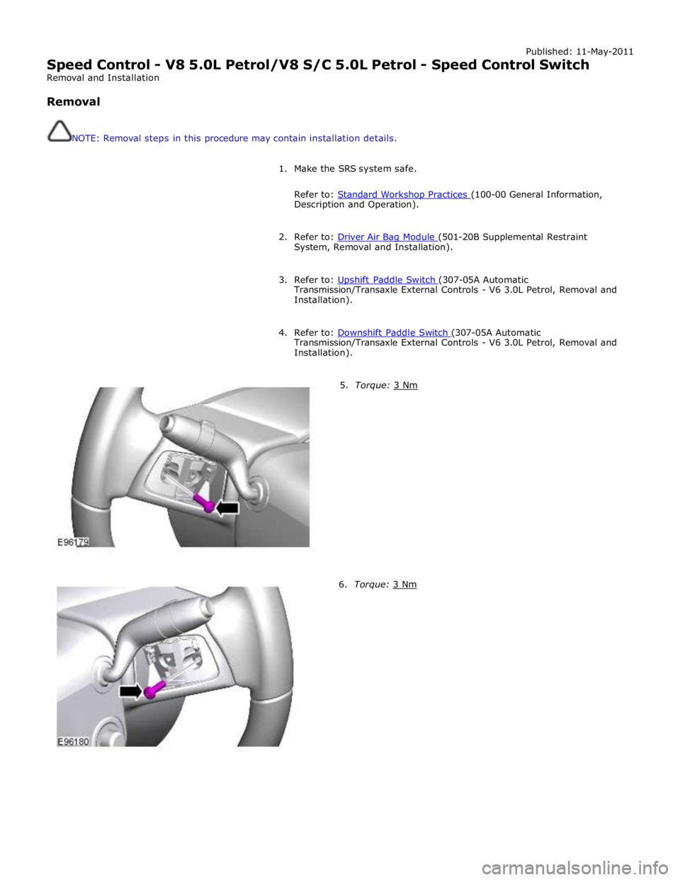
5. Torque: 3 Nm 6. Torque: 3 Nm
Page 2001 of 3039
Published: 11-May-2011
Information and Entertainment System - Steering Wheel Audio Controls
Removal and Installation
Removal
NOTE: Removal steps in this procedure may contain installation details.
1. Make the SRS system safe.
Refer to: Standard Workshop Practices (100-00 General Information, Description and Operation).
2. Refer to: Driver Air Bag Module (501-20B Supplemental Restraint System, Removal and Installation).
3. Refer to: Upshift Paddle Switch (307-05A Automatic Transmission/Transaxle External Controls - V6 3.0L Petrol, Removal and
Installation).
4. Refer to: Downshift Paddle Switch (307-05A Automatic Transmission/Transaxle External Controls - V6 3.0L Petrol, Removal and
Installation).
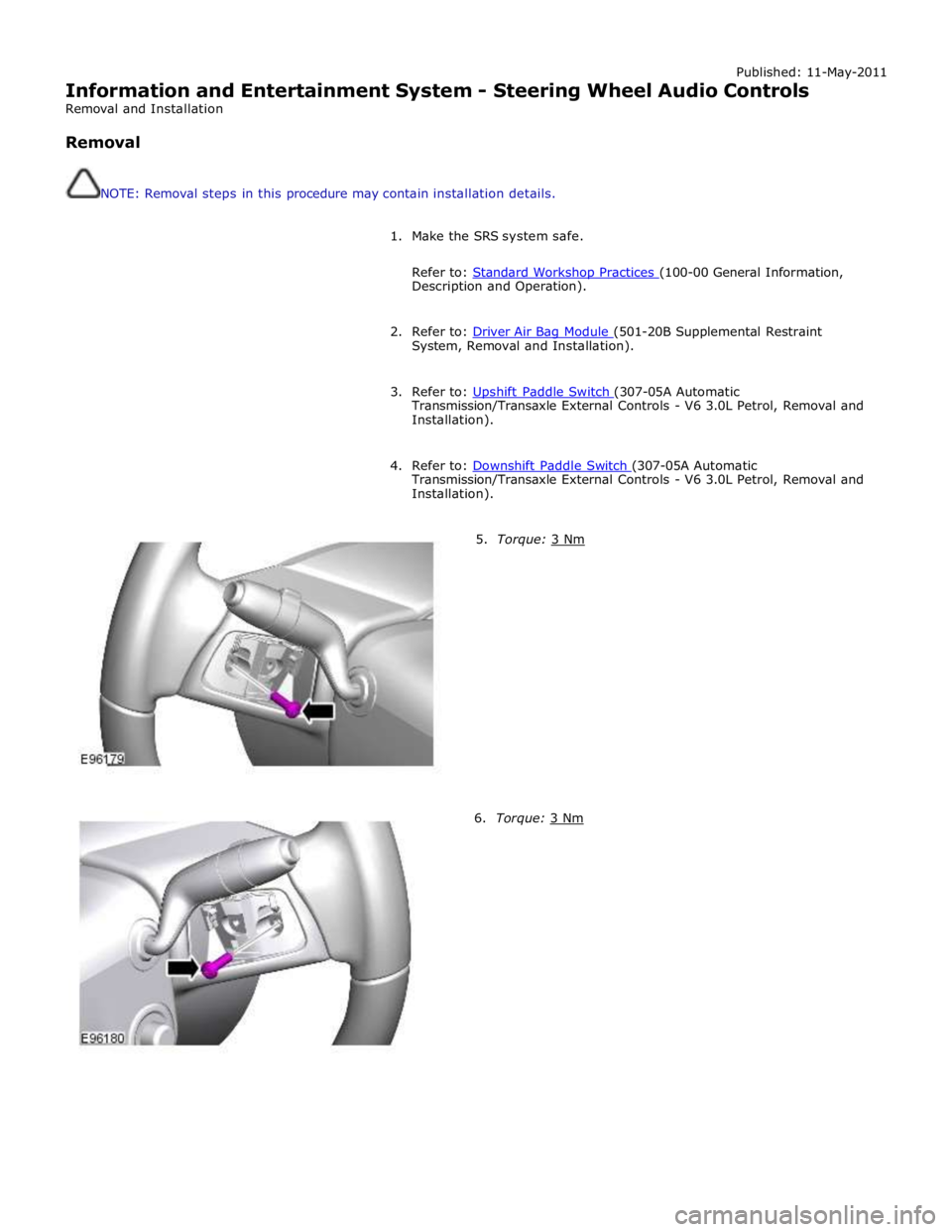
5. Torque: 3 Nm 6. Torque: 3 Nm
Page 2036 of 3039
Rear Fog Lamp
The rear fog lamps are located in separate units attached to the luggage compartment lid. The rear fog lamps each use 3 high
intensity LED's. The fog lamp locates in a recess in the luggage compartment lid has a seal to prevent the ingress of water into the luggage compartment. The lamp is secured in the recess with a metal securing clip. The rear fog lamp is activated
using a button located on the auxiliary lighting switch in the instrument panel.
LICENCE PLATE LAMPS
Two licence plate lamps are located in the luggage compartment lid trim finisher. One is located adjacent to the emergency
luggage compartment lid release key barrel cover and the other is adjacent to the rear view camera (if fitted). The licence plate
lamps are active at all times when the side lamps are operating. Each lamp can be removed from the finisher by inserting a
wide, flat screwdriver blade or similar tool in a slot between the lamp lens and the finisher and gently levering the lamp from
the surround. The bulb is a push fit in a holder which in turn is a press fit in the lamp housing.
HIGH MOUNTED STOP LAMP
The high mounted stop lamp is located at the bottom of the rear windshield. The lamp is secured to a bezel in the parcel shelf
with 2 screws.
The high mounted stop lamp uses 12, red colored LED's which illuminate through a clear lens. The high mounted stop lamp functionality is the same as that described for the stop lamps.
TURN SIGNAL INDICATOR SIDE REPEATER LAMPS
The turn signal indicator side repeaters are located in each door mirror. On vehicles from 10MY the lamp is an LED unit which illuminates in an orange color. The LED unit is secured to the mirror bezel with 2 screws and is connected to the mirror wiring harness with a 2 pin connector.
The side repeaters have the same functionality and operate in conjunction with the front and rear turn signal indicators and
the hazard warning flashers.
HAZARD FLASHERS
The hazard flashers are activated by a non-latching switch located in the switch pack located in the center of the instrument
panel. The hazard flashers operate at all times when selected and operate independent of the ignition mode.
When the hazard flashers are selected on by the driver, a ground path is momentarily completed to the CJB which activates the front and rear and side repeater turn signal indicators. A second press of the switch is sensed by the CJB and the hazard flasher are deactivated. When the hazard flashers are active, they override any request for turn signal indicator operation.
The hazard flashers can also be activated by a crash signal from the RCM. Refer to: Air Bag and Safety Belt Pretensioner Supplemental Restraint System (SRS) (501-20B Supplemental Restraint System, Description and Operation).
Page 2104 of 3039
Wiring Harnesses - Wiring Harness
Description and Operation
Introduction Published: 21-Jan-2014
CAUTION: Do not use any other heat shrink sleeve other than the approved glue lined heat shrink sleeve mentioned in
the repair procedure.
The purpose of this document is to promote quick and efficient minor repair to harness connectors or cables using approved
methods. Repairs may only be made to cables and connectors which have been mechanically, not electrically damaged. It also
applies where the whole extent of the damage can be clearly identified and rectified.
Care and neatness are essential requirements in making a perfect repair.
Caution:
This harness repair guide, does not approve repairs to any of the following circuits:
1. Any media orientated system transport network harnesses.
2. Supplement restraint system (SRS) firing circuits (Air bags).
3. Link lead assembles, which are unique to safety critical circuits such as anti-lock brake system (ABS) and thermocouple
circuits. An example of this is the ABS wheel speed sensors with moulded connectors.
4. 4. Screened cables, leads and wiring harness(s).
If any harness(s) with defective electrical connector terminals or wires from the above circuits are a concern, new
components must be installed.
Repair Components
CAUTION: Where the repair procedure indicates that a glue lined heat shrink sleeve should be applied, apply sufficient
heat to the glue lined heat shrink to melt the glue in order to provide a water tight seal. Do not over heat the glue lined heat
shrink sleeve so that the wiring harness insulation becomes damaged.
The wiring harness repair components comprises:
Pre-terminated wiring harness(s) of different sizes and types
Three sizes of butt splice connectors
A selection of colored cable identification sleeves
Two sizes of glue lined heat shrink sleeves
A suitable heat source, for shrinking heat shrink sleeves will be required.
The pre-insulated diamond grip range of electrical connector terminals and in-line, butt splice connectors are the only
acceptable product for the repairs of wiring harnesses. The butt connectors not only grip the wire but also the insulation,
making a very secure joint.
If an electrical connector terminal is not available approval for the repair is NOT given and in these circumstances a new wiring
harness must be installed.
Pre-Terminated Wiring Harness(s) and Butt Splice Connectors
The pre-terminated wiring harness(s) are supplied with the insulation in one of three colors, red, blue or yellow. The colors do
not apply to any particular circuit but to the harness wire size. See the Relationship Table in the Repair Method section.
Butt splice connectors are also supplied with red, blue or yellow coverings, which must be matched to the pre-terminated
wiring harness insulation color.
Page 2188 of 3039
Multifunction Electronic Modules - Driver Seat Module (DSM)
Removal and Installation
Removal
NOTE: Removal steps in this procedure may contain installation details. Published: 11-May-2011
1. Make the air bag supplemental restraint system (SRS) safe.
Refer to: Standard Workshop Practices (100-00 General Information, Description and Operation).
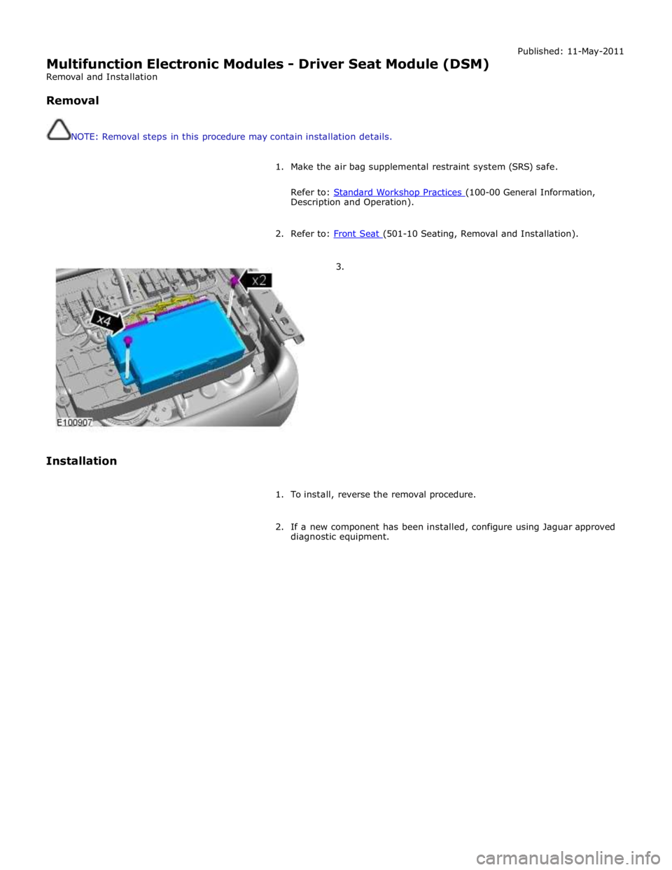
2. Refer to: Front Seat (501-10 Seating, Removal and Installation). 3.
Installation
1. To install, reverse the removal procedure.
2. If a new component has been installed, configure using Jaguar approved
diagnostic equipment.
Page 2311 of 3039
Seating - Seats - Overview
Description and Operation
OVERVIEW
Leather Seat Covers Published: 20-Nov-2013
Leather is a natural product, therefore it bears natural characteristics, such as grain variations, growth & bush marks. These
non-weakening marks show the true nature of the hide and are the hallmarks of Leather. In order to maintain the beauty of the
vehicles natural Leather upholstery it requires regular cleaning, which if neglected, may cause deterioration. Where dust and
dirt are allowed to accumulate and become ingrained in the surface of the Leather, the upholstery may become permanently
damaged.
Light coloured upholstery can be particularly susceptible to soiling and staining and care should be taken to ensure that where
there is evidence of any soiling or staining on the upholstery then this should be cleaned immediately using the Jaguar/Land
Rover approved products, failure to do this could lead to the stain becoming permanent, this applies to all leather upholstery
and is not colour specific.
Leather trimmed seats will naturally exhibit areas of creasing and wrinkling over a period of time and is a normal characteristic
as the Leather ages.
Particular care should be taken where there is evidence of soiling or staining on the leather, this should be cleaned
immediately. Failure to do this could lead to the stain becoming permanent.
Particular care should be taken to prevent damage from studs, zips and buckles.
NOTES:
Please refer to Leather care label attached to seats for more information.
Creasing and wrinkling does not represent a manufacturing defect.
Damage from studs, zips and buckles do not represent manufacturing defects.
Use only Jaguar/Land Rover approved products in accordance with the instructions for use.
General
A number of front seating options are available. An 8-way electrically adjustable driver's seat is complemented by an 8-way
electrically adjustable passenger seat. A 10-way electrically adjustable driver's seat is complemented by an 10-way electrically
adjustable front passenger seat. A 16-way electrically adjustable driver's seat is complemented by a 12-way electrically
adjustable front passenger seat.
On non-memory seats, the operation of the seats is controlled directly from the driver's seat switchpack. On memory seats,
the operation of the seat motors is controlled by a seat control module which is located on the underside of the driver's seat
frame.
The driver's seat is fitted with a seat position sensor which is located on the seat rail. The sensor is used by the RCM
(restraints control module) to determine the seat position and adjust the inflation time of the airbag deployment accordingly.
Refer to: Air Bag and Safety Belt Pretensioner Supplemental Restraint System (SRS) (501-20B Supplemental Restraint System, Description and Operation).
Page 2356 of 3039
Seating - Front Seat
Removal and Installation Published: 11-May-2011
Removal
1. Make the air bag supplemental restraint system (SRS) safe.
For additional information, refer to: Standard Workshop Practices (100-00 General Information, Description and Operation).
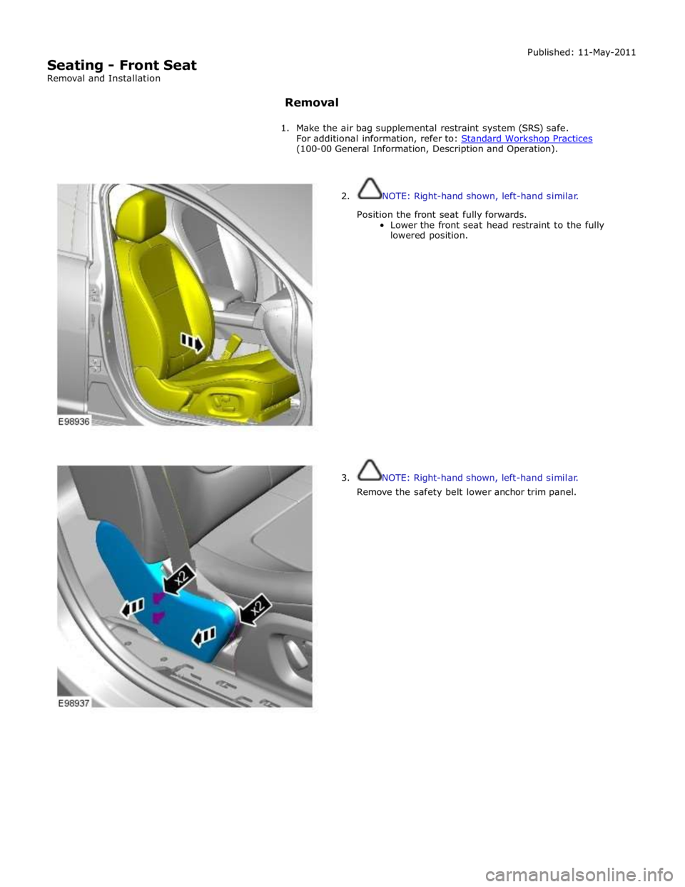
2. NOTE: Right-hand shown, left-hand similar.
Position the front seat fully forwards.
Lower the front seat head restraint to the fully
lowered position.
3. NOTE: Right-hand shown, left-hand similar.
Remove the safety belt lower anchor trim panel.