Page 2668 of 3039
Supplemental Restraint System - Side Air Bag Module
Removal and Installation
Removal
NOTE: Removal steps in this procedure may contain installation details. Published: 07-Sep-2011
1. Make the air bag supplemental restraint system (SRS) safe.
For additional information, refer to: Standard Workshop Practices (100-00 General Information, Description and Operation).
2. Disconnect the battery ground cable.
For additional information, refer to: Battery Disconnect and Connect (414-01 Battery, Mounting and Cables, General Procedures).
3. Remove the front seat.
For additional information, refer to: Front Seat (501-10 Seating, Removal and Installation).
4. Remove the front seat backrest lower rear cover.
Page 2673 of 3039

Supplemental Restraint System - Side Air Curtain Module
Removal and Installation
Removal
NOTE: Removal steps in this procedure may contain installation details.
All vehicles Published: 19-May-2011
1. Make the air bag supplemental restraint system (SRS) safe.
Refer to: Standard Workshop Practices (100-00 General Information, Description and Operation).
2. Refer to: Battery Disconnect and Connect (414-01 Battery, Mounting and Cables, General Procedures).
3. Refer to: Interior Rear View Mirror (501-09 Rear View Mirrors, Removal and Installation).
4. Refer to: Overhead Console (501-12 Instrument Panel and Console, Removal and Installation).
5. Refer to: Sun Visor (501-05 Interior Trim and Ornamentation, Removal and Installation).
6. Refer to: A-Pillar Trim Panel (501-05 Interior Trim and Ornamentation, Removal and Installation).
7. Refer to: B-Pillar Upper Trim Panel (501-05 Interior Trim and Ornamentation, Removal and Installation).
8. Refer to: C-Pillar Lower Trim Panel (501-05 Interior Trim and Ornamentation, Removal and Installation).
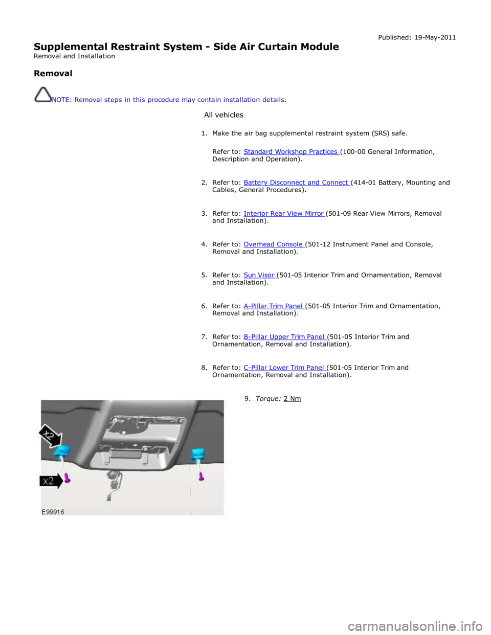
9. Torque: 2 Nm
Page 2679 of 3039
19.
20.
CAUTION: Note the fitted position of the component
prior to removal.
NOTE: Make sure that the component is installed to
the position noted on removal.
CAUTIONS:
Make sure that the clips are correctly located.
Note the fitted position of the component prior to
removal.
NOTES:
Make sure that this component is installed to the
noted removal position.
Federal vehicles only.
Torque: 9 Nm
21. WARNING: The SRS electrical connectors are unique.
DO NOT force, or attempt to connect electrical connectors
to the wrong sockets.
CAUTION: Note the fitted position of the component
prior to removal.
NOTES:
Make sure that the component is installed to the
noted removal position. www.JagDocs.com
Page 2682 of 3039

Published: 11-May-2011
Pedestrian Protection System - Pedestrian Protection System - Overview
Description and Operation
OVERVIEW
WARNING: All pyrotechnic devices are dangerous. Before performing any procedures on any pyrotechnic device, read all
information contained within the Standard Workshop Practices section of this manual.
Refer to: Standard Workshop Practices (100-00 General Information, Description and Operation).
The pedestrian protection system is designed to mitigate injuries in a pedestrian collision with the vehicle. It does this by
utilizing a pair of pyrotechnic actuators to lift the hood away from the engine, creating a cushioned impact between the
pedestrian and the vehicle.
The pedestrian protection system also includes passive protection integrated into the bumper system and bonnet structure.
WARNING: Do not fit any non-Jaguar approved accessories to the vehicle.
NOTE: The pedestrian protection system operates independently from the SRS (supplemental restraint system).