2010 JAGUAR XFR srs
[x] Cancel search: srsPage 77 of 3039

Deployment procedures and precautions as detailed in this manual should be strictly adhered to. Only personnel who have
undergone the appropriate training should undertake deployment of airbag and pre-tensioner modules. The following
precautions must be complied with:
Only use deployment equipment approved for the intended purpose.
Deployment of airbag / pre-tensioner modules must be performed in a well ventilated area which has been designated
for the purpose.
Make sure airbag / pre-tensioner modules are not damaged or ruptured before attempting to deploy.
Where local legislation exists, notify the relevant authorities of intention to deploy airbag and pretensioner units.
When deploying airbag pre-tensioner units, make sure that all personnel are at least 15 metres (45 feet) away from the
deployment zone.
Make sure deployment tool is connected correctly, in compliance with the instructions detailed in the SRS section of this
manual. In particular, make sure deployment tool is NOT connected to battery supply before connecting to airbag
module connector.
When deploying seat belt pre-tensioners, make sure pre-tensioner unit is secured correctly to the seat.
When removing deployed airbag modules and pre-tensioner units, wear protective clothing. Use gloves and seal
deployed units in a plastic bag.
Following deployment of any component of the SRS system within the vehicle, all SRS components must be replaced.
DO NOT reuse or salvage any parts of the SRS system.
Do not lean over an airbag module when connecting deployment equipment.
If a vehicle is to be scrapped, undeployed airbag modules and pre-tensioner units must be manually deployed. In this case
airbags can be deployed in the vehicle. Before deployment, make sure the airbag module is secure within its correct mounting
position. Deployment of the driver's airbag in the vehicle may damage the steering wheel; if the vehicle is not being scrapped,
deploy the module outside of the vehicle.
SRS Component Replacement Policy
CAUTIONS:
The Restraints Control Module (RCM) will log a crash fault after every impact which is severe enough to cause airbag
deployment. It is possible to have three crashes/impacts logged after one event where, for example, a front, side and
rollover has occurred. After the third fault is logged, the SRS warning lamp will be illuminated and the RCM must be
installed. After any airbag deployment a new RCM must be installed.
The SRS side impact sensor must be replaced if there are any signs of physical damage or if the restraints control module
(RCM) is registering a fault.
The following information details the policy for replacement of SRS components as a result of a vehicle accident.
Impacts which do not deploy the airbags or pre-tensioners
Check for structural damage in the area of the impact paying particular attention to bumper armatures, longitudinals and
bracketry.
Impacts which deploy the airbags or pre-tensioners
The replacement and inspection policy is dependent on the type and severity of the crash condition. The following guidelines
are the minimum that should be exercised as a result of the deployment of specific SRS components.
Check for structural damage in the area of impact paying particular attention to bumper armatures, longitudinals and
bracketry.
Front Airbag Deployment - Driver and Passenger
CAUTION: If the front airbags are deployed, the following components must be replaced:
Driver airbag module
Passenger airbag module
Fly leads (where applicable) connecting front airbag modules to SRS harness
Front seat belt buckle pre-tensioner
Rear seat belt pre-tensioners - if installed
Driver's seat belt retractor - if installed
Rotary coupler
Any front impact sensors that have been physically damaged or if a fault is being registered
Restraints control module (RCM) if the three crashes/impacts have been stored
Additionally, the following items must be inspected for damage and replaced as necessary:
Front passenger's seat belt retractor and webbing, tongue latching function, 'D' loop and body anchorage point
Rear seat belt buckles, webbing, buckle covers, body anchorage points and tongue latching function
Fascia moulding adjacent to passenger airbag module
Steering wheel
Front seat frames and head restraints
Steering column - if adjustment is lost or if there are signs of collapse
Seat belt height adjusters
Page 101 of 3039
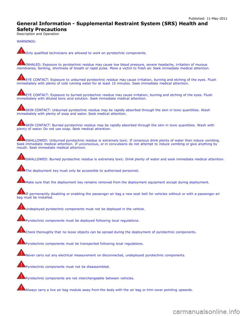
Published: 11-May-2011
General Information - Supplemental Restraint System (SRS) Health and
Safety Precautions
Description and Operation
WARNINGS:
Only qualified technicians are allowed to work on pyrotechnic components.
INHALED: Exposure to pyrotechnic residue may cause low blood pressure, severe headache, irritation of mucous
membranes, fainting, shortness of breath or rapid pulse. Move a victim to fresh air. Seek immediate medical attention.
EYE CONTACT: Exposure to unburned pyrotechnic residue may cause irritation, burning and etching of the eyes. Flush
immediately with plenty of cold running water for at least 15 minutes. Seek immediate medical attention.
EYE CONTACT: Exposure to burned pyrotechnic residue may cause irritation, burning and etching of the eyes. Flush
immediately with diluted boric acid solution. Seek immediate medical attention.
SKIN CONTACT: Unburned pyrotechnic residue may be rapidly absorbed through the skin in toxic quantities. Wash
immediately with plenty of soap and water. Seek medical attention.
SKIN CONTACT: Burned pyrotechnic residue may be rapidly absorbed through the skin in toxic quantities. Wash with
plenty of water. Do not use soap. Seek medical attention.
SWALLOWED: Unburned pyrotechnic residue is extremely toxic. If conscious drink plenty of water then induce vomiting.
Seek immediate medical attention. If unconscious, or in convulsions do not attempt to induce vomiting or give anything by
mouth. Seek immediate medical attention.
SWALLOWED: Burned pyrotechnic residue is extremely toxic. Drink plenty of water and seek immediate medical attention.
The deployment key must only be accessible to authorized personnel.
Make sure that the deployment key remains removed from the deployment equipment except during deployment.
If permenantly disabling or enabling the passenger air bag a new seat belt for vehicles without or with a passenger air
bag must be installed.
Undeployed pyrotechnic components must not be deployed in the vehicle.
Pyrotechnic components must be deployed following local regulations.
Check thoroughly that no loose objects can be spread during the deployment of pyrotechnic components.
Pyrotechnic components must be transported following local regulations.
Never carry out any electrical measurement on disconnected, undeployed pyrotechnic components.
Pyrotechnic components must not be disassembled.
Pyrotechnic components are not interchangeable between vehicles.
Always carry a live air bag module away from the body with the air bag or trim cover pointing upwards.
Page 164 of 3039
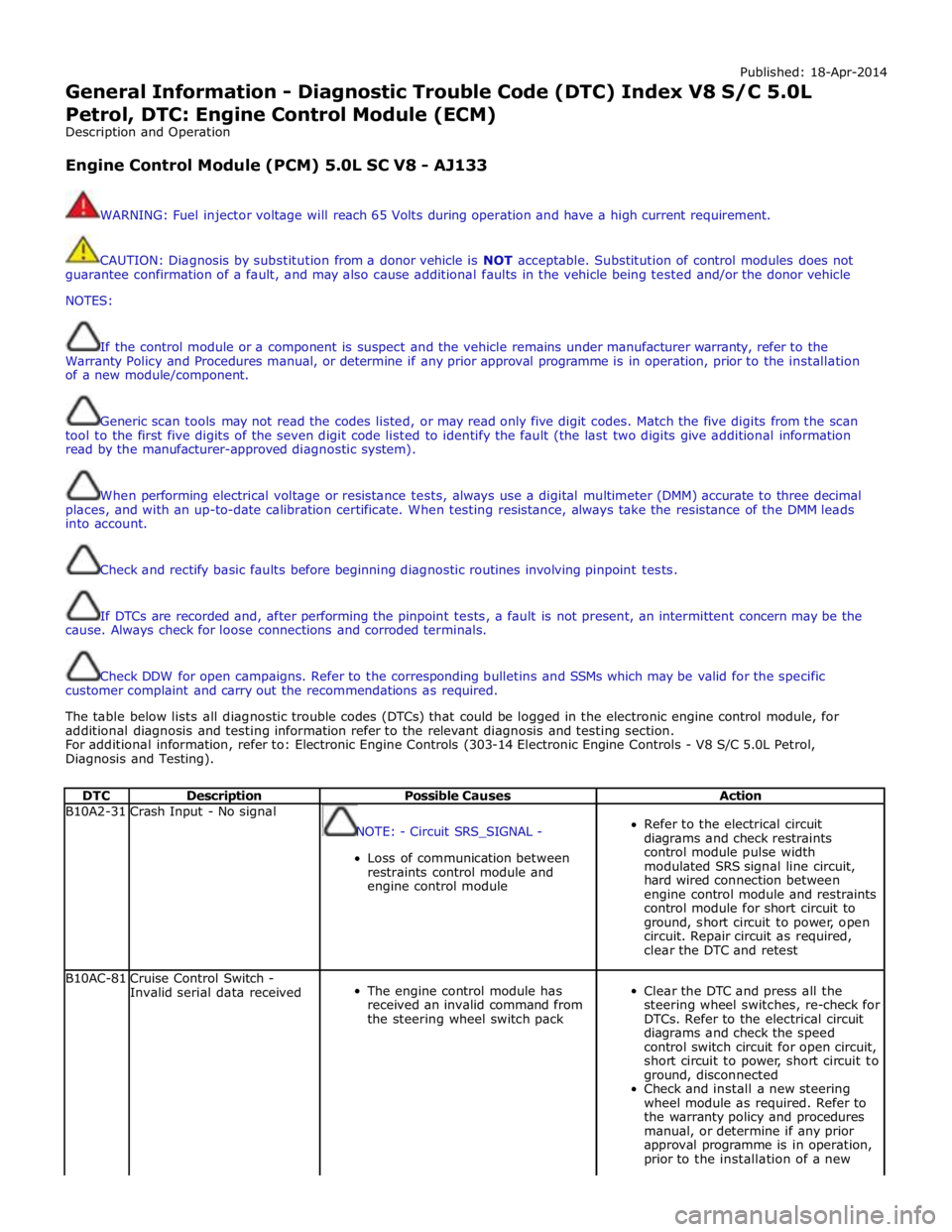
Published: 18-Apr-2014
General Information - Diagnostic Trouble Code (DTC) Index V8 S/C 5.0L
Petrol, DTC: Engine Control Module (ECM)
Description and Operation
Engine Control Module (PCM) 5.0L SC V8 - AJ133
WARNING: Fuel injector voltage will reach 65 Volts during operation and have a high current requirement.
CAUTION: Diagnosis by substitution from a donor vehicle is NOT acceptable. Substitution of control modules does not
guarantee confirmation of a fault, and may also cause additional faults in the vehicle being tested and/or the donor vehicle
NOTES:
If the control module or a component is suspect and the vehicle remains under manufacturer warranty, refer to the
Warranty Policy and Procedures manual, or determine if any prior approval programme is in operation, prior to the installation
of a new module/component.
Generic scan tools may not read the codes listed, or may read only five digit codes. Match the five digits from the scan
tool to the first five digits of the seven digit code listed to identify the fault (the last two digits give additional information
read by the manufacturer-approved diagnostic system).
When performing electrical voltage or resistance tests, always use a digital multimeter (DMM) accurate to three decimal
places, and with an up-to-date calibration certificate. When testing resistance, always take the resistance of the DMM leads
into account.
Check and rectify basic faults before beginning diagnostic routines involving pinpoint tests.
If DTCs are recorded and, after performing the pinpoint tests, a fault is not present, an intermittent concern may be the
cause. Always check for loose connections and corroded terminals.
Check DDW for open campaigns. Refer to the corresponding bulletins and SSMs which may be valid for the specific
customer complaint and carry out the recommendations as required.
The table below lists all diagnostic trouble codes (DTCs) that could be logged in the electronic engine control module, for
additional diagnosis and testing information refer to the relevant diagnosis and testing section.
For additional information, refer to: Electronic Engine Controls (303-14 Electronic Engine Controls - V8 S/C 5.0L Petrol,
Diagnosis and Testing).
DTC Description Possible Causes Action B10A2-31 Crash Input - No signal
NOTE: - Circuit SRS_SIGNAL -
Loss of communication between
restraints control module and
engine control module
Refer to the electrical circuit
diagrams and check restraints
control module pulse width
modulated SRS signal line circuit,
hard wired connection between
engine control module and restraints
control module for short circuit to
ground, short circuit to power, open
circuit. Repair circuit as required,
clear the DTC and retest B10AC-81
Cruise Control Switch -
Invalid serial data received
The engine control module has
received an invalid command from
the steering wheel switch pack
Clear the DTC and press all the
steering wheel switches, re-check for
DTCs. Refer to the electrical circuit
diagrams and check the speed
control switch circuit for open circuit,
short circuit to power, short circuit to
ground, disconnected
Check and install a new steering
wheel module as required. Refer to
the warranty policy and procedures
manual, or determine if any prior
approval programme is in operation,
prior to the installation of a new
Page 166 of 3039

DTC Description Possible Causes Action B11DB-87
Battery Monitoring Module -
Missing message
NOTE: - Circuit BATTERY -
Battery signal line circuit fault
Refer to the electrical wiring
diagrams and check the battery
monitoring system module circuit for
open circuit, short circuit to ground,
short circuit to power
Refer to the electrical circuit
diagrams and check the LIN circuit
for short circuit to ground, short
circuit to power, open circuit B1206-68
Crash Occurred - Event
information
NOTE: - Circuit SRS_SIGNAL -
Engine control module has
detected the vehicle has crashed -
event information DTC only
Refer to the electrical circuit
diagrams and check the engine
control module to restraints control
module circuit for short circuit to
ground, short circuit to power, open
circuit. Repair circuit as required,
clear the DTC and retest C0031-00
Left Front Wheel Speed
Sensor - No sub type
information
Invalid data received from anti-lock
braking system module - left front
wheel speed signal fault
Check anti-lock braking system
module for related DTCs and refer to
relevant DTC index C0034-00
Right Front Wheel Speed
Sensor - No sub type
information
Invalid data received from anti-lock
braking system module - right front
wheel speed signal fault
Check anti-lock braking system
module for related DTCs and refer to
relevant DTC index C0037-00
Left Rear Wheel Speed
Sensor - No sub type
information
Invalid data received from anti-lock
braking system module - left rear
wheel speed signal fault
Check anti-lock braking system
module for related DTCs and refer to
relevant DTC index C003A-00
Right Rear Wheel Speed
Sensor - No sub type
information
Invalid data received from anti-lock
braking system module - right rear
wheel speed signal fault
Check anti-lock braking system
module for related DTCs and refer to
relevant DTC index P0010-13
Intake (A) Camshaft Position
Actuator (Bank 1) - Circuit
open
NOTE: - Circuit VFS_IN_A -
Intake (A) camshaft position
actuator (Bank 1) open circuit
Engine control module interface
harness open circuit
Refer to the electrical circuit
diagrams and check intake (A)
camshaft position actuator (Bank 1)
circuit for open circuit
Refer to the electrical circuit
diagrams and check engine control
module interface harness for open
circuit P0011-00
Intake (A) Camshaft Position
Timing - Over-Advanced
(Bank 1) - No sub type
information
NOTE: - Circuit VFS_IN_A -
Intake (A) camshaft position
actuator (Bank 1) open circuit
Engine control module interface
harness open circuit
Refer to the electrical circuit
diagrams and check intake (A)
camshaft position actuator (Bank 1)
circuit for open circuit
Refer to the electrical circuit
diagrams and check engine control
module interface harness for open
circuit P0013-13
Exhaust (B) Camshaft
Position Actuator (Bank 1) -
Circuit open
NOTE: - Circuit VFS_EX_A -
Exhaust (B) camshaft position
actuator (Bank 1) open circuit
Engine control module interface
harness open circuit
Refer to the electrical circuit
diagrams and check exhaust (B)
camshaft position actuator (Bank 1)
circuit for open circuit
Refer to the electrical circuit
diagrams and check engine control
module interface harness for open
circuit P0015-00
Exhaust (B) Camshaft
Position Timing -
Over-Retarded (Bank 1) - No
sub type information
NOTE: - Circuit VFS_EX_A -
Exhaust (B) camshaft position
actuator (Bank 1) open circuit,
short circuit to ground, short circuit
to power
Check for related DTC P0365-00.
Refer to the electrical circuit
diagrams and check exhaust (B)
camshaft position actuator (Bank 1)
for open circuit, short circuit to
ground, short circuit to power www.JagDocs.com
Page 203 of 3039
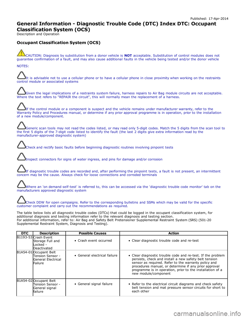
Published: 17-Apr-2014
General Information - Diagnostic Trouble Code (DTC) Index DTC: Occupant Classification System (OCS)
Description and Operation
Occupant Classification System (OCS)
CAUTION: Diagnosis by substitution from a donor vehicle is NOT acceptable. Substitution of control modules does not
guarantee confirmation of a fault, and may also cause additional faults in the vehicle being tested and/or the donor vehicle
NOTES:
It is advisable not to use a cellular phone or to have a cellular phone in close proximity when working on the restraints
control module or associated systems
Given the legal implications of a restraints system failure, harness repairs to Air Bag module circuits are not acceptable.
Where the text refers to "REPAIR the circuit", this will normally mean the replacement of a harness.
If the control module or a component is suspect and the vehicle remains under manufacturer warranty, refer to the
Warranty Policy and Procedures manual, or determine if any prior approval programme is in operation, prior to the installation
of a new module/component.
Generic scan tools may not read the codes listed, or may read only 5-digit codes. Match the 5 digits from the scan tool to
the first 5 digits of the 7-digit code listed to identify the fault (the last 2 digits give extra information read by the
manufacturer-approved diagnostic system)
Check and rectify basic faults before beginning diagnostic routines involving pinpoint tests
Inspect connectors for signs of water ingress, and pins for damage and/or corrosion
If diagnostic trouble codes are recorded and, after performing the pinpoint tests, a fault is not present, an intermittent
concern may be the cause. Always check for loose connections and corroded terminals
Where an 'on demand self-test' is referred to, this can be accessed via the 'diagnostic trouble code monitor' tab on the
manufacturers approved diagnostic system
Check DDW for open campaigns. Refer to the corresponding bulletins and SSMs which may be valid for the specific
customer complaint and carry out the recommendations as required.
The table below lists all diagnostic trouble codes (DTCs) that could be logged in the occupant classification system, for
additional diagnosis and testing information refer to the relevant diagnosis and testing section.
For additional information, refer to: Air Bag and Safety Belt Pretensioner Supplemental Restraint System (SRS) (501-20
Supplemental Restraint System, Diagnosis and Testing).
DTC Description Possible Causes Action B1193-53
Crash Event
Storage Full and
Locked -
Deactivated
Crash event occurred
Clear diagnostic trouble code and re-test B1A54-01
Occupant Belt Tension Sensor -
General Electrical
Failure
General electrical failure
Clear diagnostic trouble code and re-test. If the problem
persists, check and install a new safety belt tension
sensor as required. Refer to the warranty policy and
procedures manual, or determine if any prior approval
programme is in operation, prior to the installation of a
new module/component B1A54-02
Occupant Belt Tension Sensor -
General signal
failure
General signal failure
Refer to the electrical circuit diagrams and check safety
belt tension and mat pressure sensor circuits for short to
each other
Page 231 of 3039
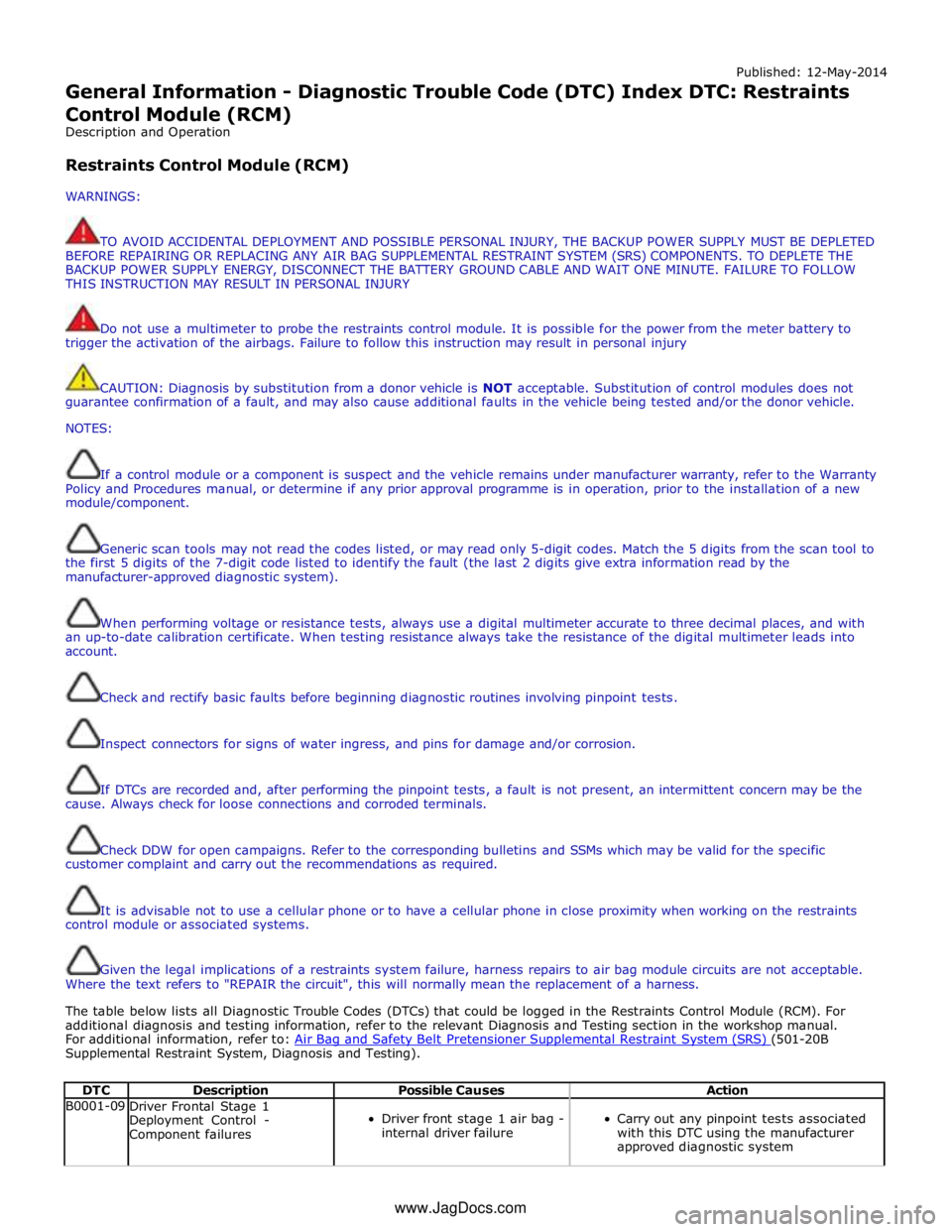
Published: 12-May-2014
General Information - Diagnostic Trouble Code (DTC) Index DTC: Restraints
Control Module (RCM)
Description and Operation
Restraints Control Module (RCM)
WARNINGS:
TO AVOID ACCIDENTAL DEPLOYMENT AND POSSIBLE PERSONAL INJURY, THE BACKUP POWER SUPPLY MUST BE DEPLETED
BEFORE REPAIRING OR REPLACING ANY AIR BAG SUPPLEMENTAL RESTRAINT SYSTEM (SRS) COMPONENTS. TO DEPLETE THE
BACKUP POWER SUPPLY ENERGY, DISCONNECT THE BATTERY GROUND CABLE AND WAIT ONE MINUTE. FAILURE TO FOLLOW
THIS INSTRUCTION MAY RESULT IN PERSONAL INJURY
Do not use a multimeter to probe the restraints control module. It is possible for the power from the meter battery to
trigger the activation of the airbags. Failure to follow this instruction may result in personal injury
CAUTION: Diagnosis by substitution from a donor vehicle is NOT acceptable. Substitution of control modules does not
guarantee confirmation of a fault, and may also cause additional faults in the vehicle being tested and/or the donor vehicle.
NOTES:
If a control module or a component is suspect and the vehicle remains under manufacturer warranty, refer to the Warranty
Policy and Procedures manual, or determine if any prior approval programme is in operation, prior to the installation of a new
module/component.
Generic scan tools may not read the codes listed, or may read only 5-digit codes. Match the 5 digits from the scan tool to
the first 5 digits of the 7-digit code listed to identify the fault (the last 2 digits give extra information read by the
manufacturer-approved diagnostic system).
When performing voltage or resistance tests, always use a digital multimeter accurate to three decimal places, and with
an up-to-date calibration certificate. When testing resistance always take the resistance of the digital multimeter leads into
account.
Check and rectify basic faults before beginning diagnostic routines involving pinpoint tests.
Inspect connectors for signs of water ingress, and pins for damage and/or corrosion.
If DTCs are recorded and, after performing the pinpoint tests, a fault is not present, an intermittent concern may be the
cause. Always check for loose connections and corroded terminals.
Check DDW for open campaigns. Refer to the corresponding bulletins and SSMs which may be valid for the specific
customer complaint and carry out the recommendations as required.
It is advisable not to use a cellular phone or to have a cellular phone in close proximity when working on the restraints
control module or associated systems.
Given the legal implications of a restraints system failure, harness repairs to air bag module circuits are not acceptable.
Where the text refers to "REPAIR the circuit", this will normally mean the replacement of a harness.
The table below lists all Diagnostic Trouble Codes (DTCs) that could be logged in the Restraints Control Module (RCM). For
additional diagnosis and testing information, refer to the relevant Diagnosis and Testing section in the workshop manual.
For additional information, refer to: Air Bag and Safety Belt Pretensioner Supplemental Restraint System (SRS) (501-20B Supplemental Restraint System, Diagnosis and Testing).
DTC Description Possible Causes Action B0001-09
Driver Frontal Stage 1
Deployment Control -
Component failures
Driver front stage 1 air bag -
internal driver failure
Carry out any pinpoint tests associated
with this DTC using the manufacturer
approved diagnostic system www.JagDocs.com
Page 792 of 3039
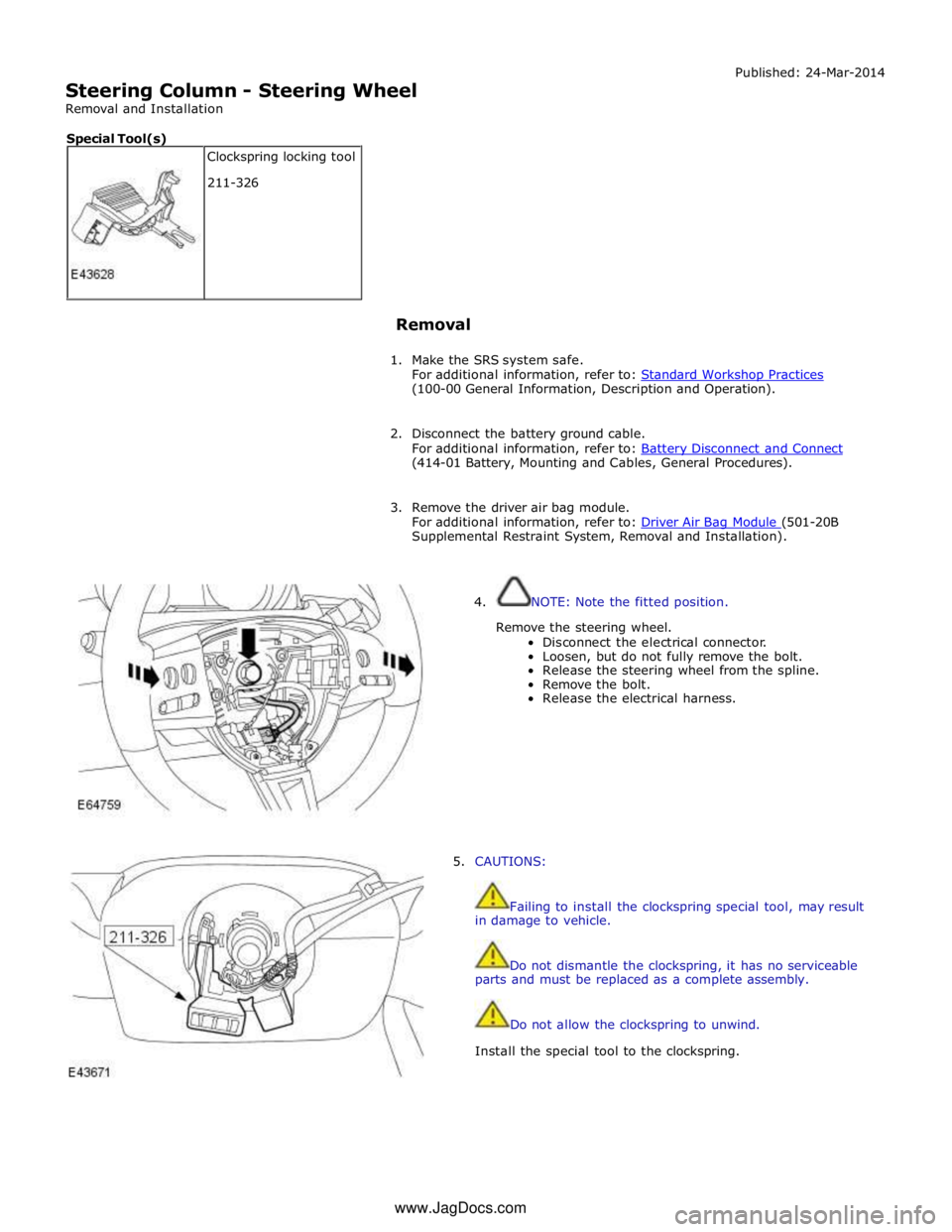
Steering Column - Steering Wheel
Removal and Installation Published: 24-Mar-2014
Removal
1. Make the SRS system safe.
For additional information, refer to: Standard Workshop Practices (100-00 General Information, Description and Operation).
2. Disconnect the battery ground cable.
For additional information, refer to: Battery Disconnect and Connect (414-01 Battery, Mounting and Cables, General Procedures).
3. Remove the driver air bag module.
For additional information, refer to: Driver Air Bag Module (501-20B Supplemental Restraint System, Removal and Installation).
4. NOTE: Note the fitted position.
Remove the steering wheel.
Disconnect the electrical connector.
Loosen, but do not fully remove the bolt.
Release the steering wheel from the spline.
Remove the bolt.
Release the electrical harness.
5. CAUTIONS:
Failing to install the clockspring special tool, may result
in damage to vehicle.
Do not dismantle the clockspring, it has no serviceable
parts and must be replaced as a complete assembly.
Do not allow the clockspring to unwind.
Install the special tool to the clockspring. Clockspring locking tool
211-326 Special Tool(s) www.JagDocs.com
Page 1372 of 3039
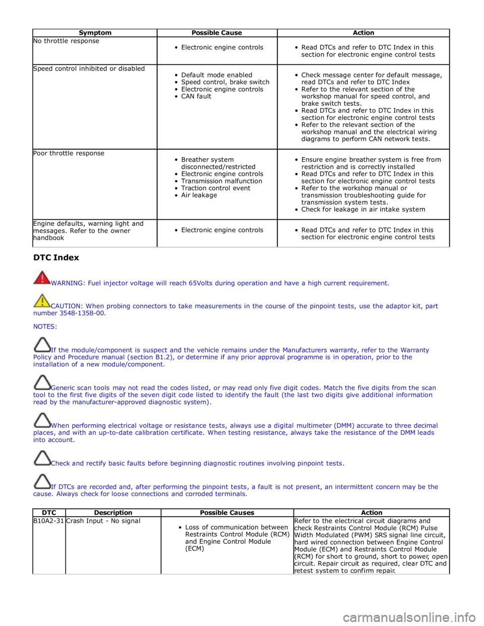
Symptom Possible Cause Action No throttle response
Electronic engine controls
Read DTCs and refer to DTC Index in this
section for electronic engine control tests Speed control inhibited or disabled
Default mode enabled
Speed control, brake switch
Electronic engine controls
CAN fault
Check message center for default message,
read DTCs and refer to DTC Index
Refer to the relevant section of the
workshop manual for speed control, and
brake switch tests.
Read DTCs and refer to DTC Index in this
section for electronic engine control tests
Refer to the relevant section of the
workshop manual and the electrical wiring
diagrams to perform CAN network tests. Poor throttle response
Breather system
disconnected/restricted
Electronic engine controls
Transmission malfunction
Traction control event
Air leakage
Ensure engine breather system is free from
restriction and is correctly installed
Read DTCs and refer to DTC Index in this
section for electronic engine control tests
Refer to the workshop manual or
transmission troubleshooting guide for
transmission system tests.
Check for leakage in air intake system Engine defaults, warning light and
messages. Refer to the owner
handbook
Electronic engine controls
Read DTCs and refer to DTC Index in this
section for electronic engine control tests DTC Index
WARNING: Fuel injector voltage will reach 65Volts during operation and have a high current requirement.
CAUTION: When probing connectors to take measurements in the course of the pinpoint tests, use the adaptor kit, part
number 3548-1358-00.
NOTES:
If the module/component is suspect and the vehicle remains under the Manufacturers warranty, refer to the Warranty
Policy and Procedure manual (section B1.2), or determine if any prior approval programme is in operation, prior to the
installation of a new module/component.
Generic scan tools may not read the codes listed, or may read only five digit codes. Match the five digits from the scan
tool to the first five digits of the seven digit code listed to identify the fault (the last two digits give additional information
read by the manufacturer-approved diagnostic system).
When performing electrical voltage or resistance tests, always use a digital multimeter (DMM) accurate to three decimal
places, and with an up-to-date calibration certificate. When testing resistance, always take the resistance of the DMM leads
into account.
Check and rectify basic faults before beginning diagnostic routines involving pinpoint tests.
If DTCs are recorded and, after performing the pinpoint tests, a fault is not present, an intermittent concern may be the
cause. Always check for loose connections and corroded terminals.
DTC Description Possible Causes Action B10A2-31 Crash Input - No signal
Loss of communication between
Restraints Control Module (RCM)
and Engine Control Module
(ECM) Refer to the electrical circuit diagrams and
check Restraints Control Module (RCM) Pulse
Width Modulated (PWM) SRS signal line circuit,
hard wired connection between Engine Control
Module (ECM) and Restraints Control Module
(RCM) for short to ground, short to power, open
circuit. Repair circuit as required, clear DTC and
retest system to confirm repair.