Page 2724 of 3039
Cooper Pegler
Burgess Hill
Sussex
RH 15 9LA
Telephone (014446) 42526
Sika Ltd
Watchmead
Welwyn Garden City
Hertfordshire
AL7 1BQ
Telephone (01707) 394444
www.sika.co.uk
SATA Spray Equipment
Minden Industrial equipment
16 Greyfriars Road
Moreton Hall
Bury St Edmunds
Suffolk
IP32 7DX
Telephone (01284) 760791
www.sata.com
Henkel Loctite Adhesives Limited
Technologies House
Wood Lane End
Hemel Hempstead
Hertfordshire
HP2 4RQ
Telephone (01442) 278000
www.loctite.co.uk
Teroson
Henkel Ltd
Apollo Court
2 Bishops Square Business Park
Hatfield
Hertfordshire
AL10 9EY
Telephone (01707) 635000
www.henkel.co.uk
Underbody sealer
Under floor areas and the front part of the spare wheel well are treated with a plastisol PVC underbody sealer. This material is
not suitable for re-treatment. When repairing areas of underbody sealer, strip the factory-applied underbody sealer back to a
suitable break point. Ensure that a clean metal surface is exposed and that the edge of the existing adheres soundly to the
panel.
Apply new underbody sealer between primer and surface paint operations. Apply seam sealer as necessary before application
of underbody sealer. Ensure that blanking plugs and grommets in the floor pan (except those used for wax injection) are fitted
before underbody sealer application. Refit any heat-fusible plugs which have been disturbed in repair with the aid of a hot air
blower, or replace with rubber grommets
CAUTION: Ensure that suspension units, wheels, tires, power unit, drive shafts, exhaust and brakes, (including all
mounting points), are shielded prior to application of fresh underbody sealer. www.JagDocs.com
Page 2941 of 3039
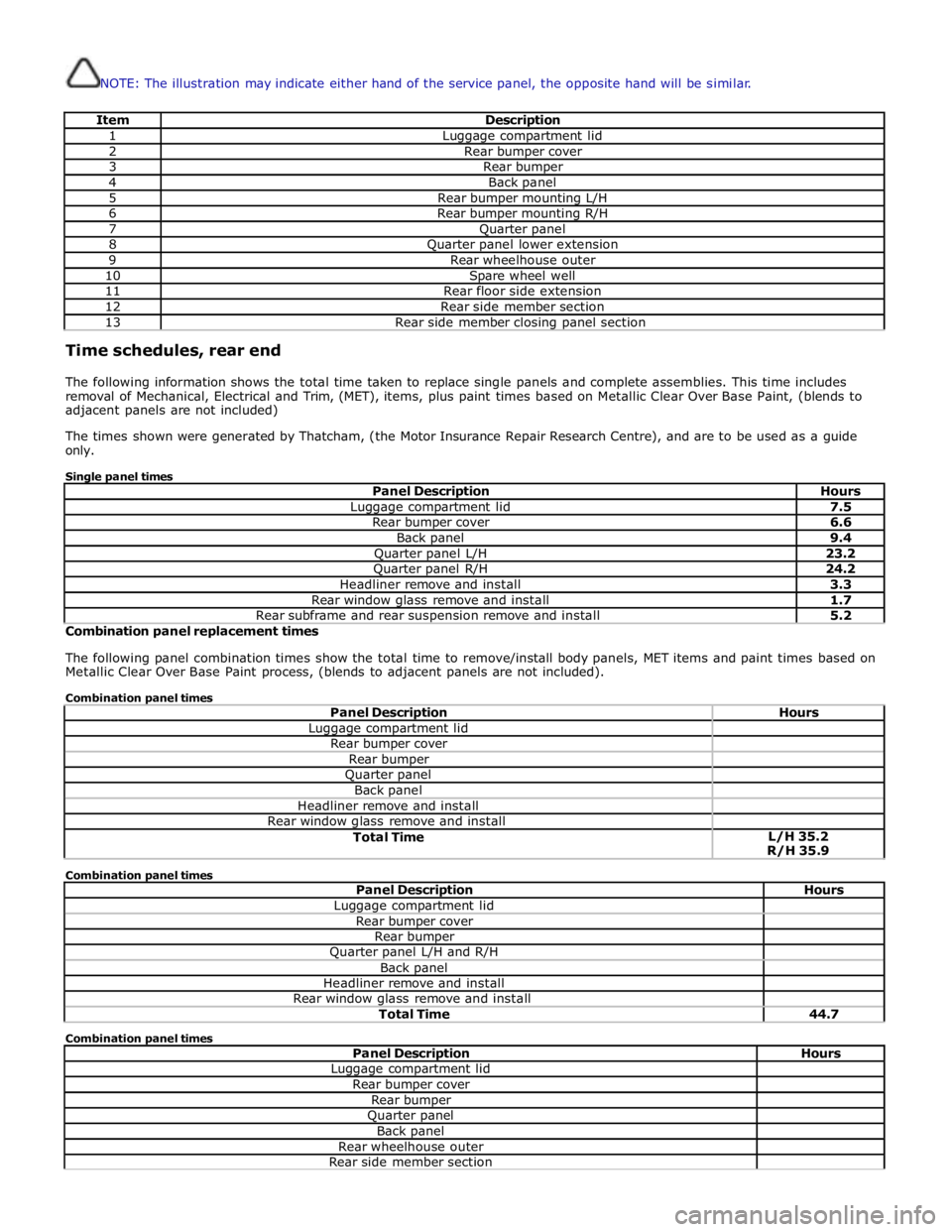
NOTE: The illustration may indicate either hand of the service panel, the opposite hand will be similar.
Item Description 1 Luggage compartment lid 2 Rear bumper cover 3 Rear bumper 4 Back panel 5 Rear bumper mounting L/H 6 Rear bumper mounting R/H 7 Quarter panel 8 Quarter panel lower extension 9 Rear wheelhouse outer 10 Spare wheel well 11 Rear floor side extension 12 Rear side member section 13 Rear side member closing panel section Time schedules, rear end
The following information shows the total time taken to replace single panels and complete assemblies. This time includes
removal of Mechanical, Electrical and Trim, (MET), items, plus paint times based on Metallic Clear Over Base Paint, (blends to
adjacent panels are not included)
The times shown were generated by Thatcham, (the Motor Insurance Repair Research Centre), and are to be used as a guide
only.
Single panel times
Panel Description Hours Luggage compartment lid 7.5 Rear bumper cover 6.6 Back panel 9.4 Quarter panel L/H 23.2 Quarter panel R/H 24.2 Headliner remove and install 3.3 Rear window glass remove and install 1.7 Rear subframe and rear suspension remove and install 5.2 Combination panel replacement times
The following panel combination times show the total time to remove/install body panels, MET items and paint times based on
Metallic Clear Over Base Paint process, (blends to adjacent panels are not included).
Combination panel times
Panel Description Hours Luggage compartment lid Rear bumper cover Rear bumper Quarter panel Back panel Headliner remove and install Rear window glass remove and install Total Time L/H 35.2
R/H 35.9 Combination panel times
Panel Description Hours Luggage compartment lid Rear bumper cover Rear bumper Quarter panel L/H and R/H Back panel Headliner remove and install Rear window glass remove and install Total Time 44.7 Combination panel times
Panel Description Hours Luggage compartment lid Rear bumper cover Rear bumper Quarter panel Back panel Rear wheelhouse outer Rear side member section
Page 2942 of 3039
Rear side member closing panel section Spare wheel well Rear floor side extension Rear subframe and rear suspension remove and install Headliner remove and install Rear window glass remove and install Total Time L/H 54.0
R/H 54.5 Combination panel times
Panel Description Hours Luggage compartment lid Rear bumper cover Rear bumper Quarter panel L/H and R/H Back panel Rear wheelhouse outer L/H and R/H Rear side member section L/H and R/H Rear side member closing panel section L/H and R/H Spare wheel well Rear floor side extension L/H and R/H Rear subframe and rear suspension remove and install Headliner remove and install Rear window glass remove and install Total Time 70.5 Combination panel times
Panel Description Hours Luggage compartment lid Rear bumper cover Rear bumper Quarter panel Back panel Rear side member section Rear side member closing panel section Spare wheel well Rear floor side extension Rear subframe and rear suspension remove and install Headliner remove and install Rear window glass remove and install Total Time L/H 50.1
R/H 50.2 Combination panel times
Panel Description Hours Rear bumper cover Rear bumper Back panel Spare wheel well Rear subframe and rear suspension remove and install Total Time 26.8
Page 2944 of 3039
Interior Trim and Ornamentation, Removal and Installation).
14.
15. Remove the spare wheel and tire (if equipped).
Remove the subwoofer speaker (if equipped).
16.
Release and position the back panel and loadspace wiring harness to
one side.
17. Remove the luggage compartment latch striker.
18. Remove the right-hand and left-hand forced air extraction grilles.
19. Remove the right-hand and left-hand muffler and tailpipe.
For additional information, refer to: Muffler and Tailpipe (309-00A,
Removal and Installation) /
Muffler and Tailpipe (309-00B, Removal and Installation) /
Muffler and Tailpipe (309-00C, Removal and Installation).
20. Remove the right-hand and left-hand muffler and tailpipe heatshield. www.JagDocs.com
Page 2974 of 3039
Rear End Sheet Metal Repairs - Rear Side Member Section
Removal and Installation
Removal Published: 11-May-2011
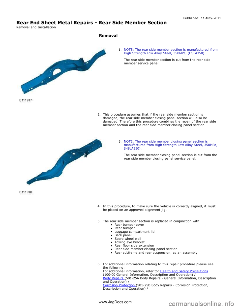
1. NOTE: The rear side member section is manufactured from
High Strength Low Alloy Steel, 350MPa, (HSLA350).
The rear side member section is cut from the rear side
member service panel.
2. This procedure assumes that if the rear side member section is
damaged, the rear side member closing panel section will also be
damaged. Therefore this procedure combines the repair of the rear side
member section and the rear side member closing panel section.
3. NOTE: The rear side member closing panel section is
manufactured from High Strength Low Alloy Steel, 350MPa,
(HSLA350).
The rear side member closing panel section is cut from the
rear side member closing panel service panel.
4. In this procedure, to make sure the vehicle is correctly aligned, it must
be placed on an approved alignment jig.
5. The rear side member section is replaced in conjunction with:
Rear bumper cover
Rear bumper
Luggage compartment lid
Back panel
Spare wheel well
Towing eye bracket
Rear floor side extension
Rear side member closing panel section
Rear subframe and rear suspension, as an assembly
6. For additional information relating to this repair procedure please see
the following:
For additional information, refer to: Health and Safety Precautions (100-00 General Information, Description and Operation) /
Body Repairs (501-25A Body Repairs - General Information, Description and Operation) /
Corrosion Protection (501-25B Body Repairs - Corrosion Protection, Description and Operation) / www.JagDocs.com
Page 2975 of 3039
Body and Frame (501-26 Body Repairs - Vehicle Specific Information and Tolerance Checks, Description and Operation).
7. Disconnect the generator electrical connectors.
8. Remove the luggage compartment lid.
For additional information, refer to: Luggage Compartment Lid (501-03 Body Closures, Removal and Installation).
9. Remove the spare wheel well.
For additional information, refer to: Spare W heel Well (501-30 Rear End Sheet Metal Repairs, Removal and Installation).
10. Remove the rear floor side extension.
For additional information, refer to: Rear Floor Side Extension (501-30 Rear End Sheet Metal Repairs, Removal and Installation).
11. Remove the rear muffler hanger bracket from the side member.
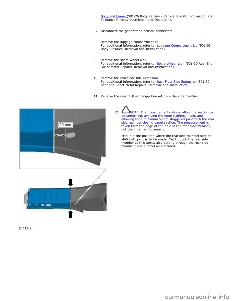
12. NOTE: The measurements shown allow the section to
be performed, avoiding the inner reinforcements and
allowing for a minimum 50mm staggered joint with the rear
side member closing panel section. The measurement is
taken from the edge of the hole in the rear side member,
not the inner reinforcement.
Mark out the position where the rear side member section
MAG butt joint is to be made. Cut through the rear side
member at this point, also cutting through the rear side
member closing panel as indicated.
Page 2992 of 3039
Rear End Sheet Metal Repairs - Spare Wheel Well
Removal and Installation
Removal Published: 11-May-2011
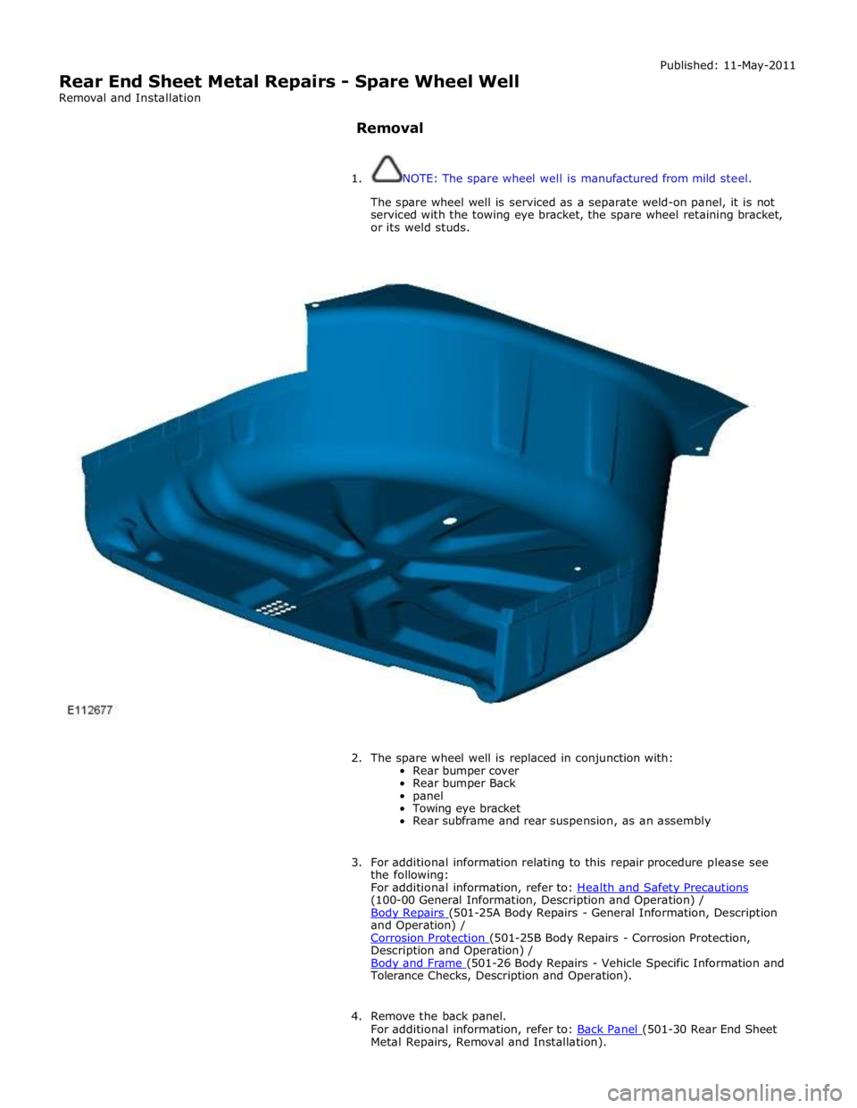
1. NOTE: The spare wheel well is manufactured from mild steel.
The spare wheel well is serviced as a separate weld-on panel, it is not
serviced with the towing eye bracket, the spare wheel retaining bracket,
or its weld studs.
2. The spare wheel well is replaced in conjunction with:
Rear bumper cover
Rear bumper Back
panel
Towing eye bracket
Rear subframe and rear suspension, as an assembly
3. For additional information relating to this repair procedure please see
the following:
For additional information, refer to: Health and Safety Precautions (100-00 General Information, Description and Operation) /
Body Repairs (501-25A Body Repairs - General Information, Description and Operation) /
Corrosion Protection (501-25B Body Repairs - Corrosion Protection, Description and Operation) /
Body and Frame (501-26 Body Repairs - Vehicle Specific Information and Tolerance Checks, Description and Operation).
4. Remove the back panel.
For additional information, refer to: Back Panel (501-30 Rear End Sheet Metal Repairs, Removal and Installation).
Page 2996 of 3039
14. NOTE: Retain the old panel for reference to the weld stud location
points.
Separate the joints and remove the old panel.
15. NOTE: Drill out from inside the spare wheel well to allow spot
welds to be used in installation. If undamaged, retain the towing eye
bracket for re-use on installation.
Drill out the spot welds and remove the towing eye bracket from the old
panel.