2010 JAGUAR XFR change time
[x] Cancel search: change timePage 1423 of 3039
The TCM can be reprogrammed using a Jaguar approved diagnostic system using a flash code. The TCM processor has a 440 kb internal flash memory. Of this capacity, approximately 370 kb are used by the basic transmission program. The remainder,
approximately 70 kb is used to store vehicle-specific application data.
Engine Stall
If the vehicle stalls it will coast down in gear, with the transmission providing drive to the engine. A restart can be attempted
at this point and the engine may start and the driver can continue.
If the coast down speed reduces such that the speed of the engine is less than 600 rev/min, the transmission will go to
neutral, D illumination will flash in the instrument cluster. The driver needs to select neutral or park and then press the brake
pedal to restart the engine.
If the start/stop button is pressed when driving, the message ENGINE STOP BUTTON PRESSED is displayed in the message
center but there will be no change to the ignition state. If the driver requires to switch off the engine, the start/stop button
must be pressed for a second time. The engine will be stopped and will be back driven by the transmission as the vehicle
coasts down. When the engine speed is less than 600 rev/min the transmission engages neutral (flashing D illumination in the
instrument cluster). When vehicle speed is less than 2 km/h (1.2 mph) Park is engaged. The JaguarDrive selector automatically
rotates back to its lowered P position and the vehicle ignition is switched off.
The park engagement is prevented in a stall case as the ignition power is on and D was the last selected gear. The park
engagement speed at ignition off is from the least value of the wheel speeds (CAN signal) and transmission output speed (internal signal).
TRANSMISSION Component Description
The transmission comprises the main casing which houses all of the transmission components. The main casing also
incorporates an integral bell housing.
A fluid pan is attached to the lower face of the main casing and is secured with bolts. The fluid pan is sealed to the main
casing with a gasket. Removal of the fluid pan allows access to the Mechatronic valve block. The fluid pan has a magnet
located around the drain plug which collects any metallic particles present in the transmission fluid.
A fluid filter is located inside the fluid pan. If the transmission fluid becomes contaminated or after any service work, the fluid
pan with integral filter must be replaced.
The integral bell housing provides protection for the torque converter assembly and also provides the attachment for the
gearbox to the engine cylinder block. The torque converter is a non-serviceable assembly which also contains the lock-up clutch
mechanism. The torque converter drives a crescent type pump via drive tangs. The fluid pump is located in the main casing,
behind the torque converter.
The main casing contains the following major components:
Input shaft
Output shaft
Mechatronic valve block which contains the solenoids, speed sensors and the TCM Three rotating multiplate drive clutches
Two fixed multiplate brake clutches
A single planetary gear train and a double planetary gear train.
Page 1532 of 3039
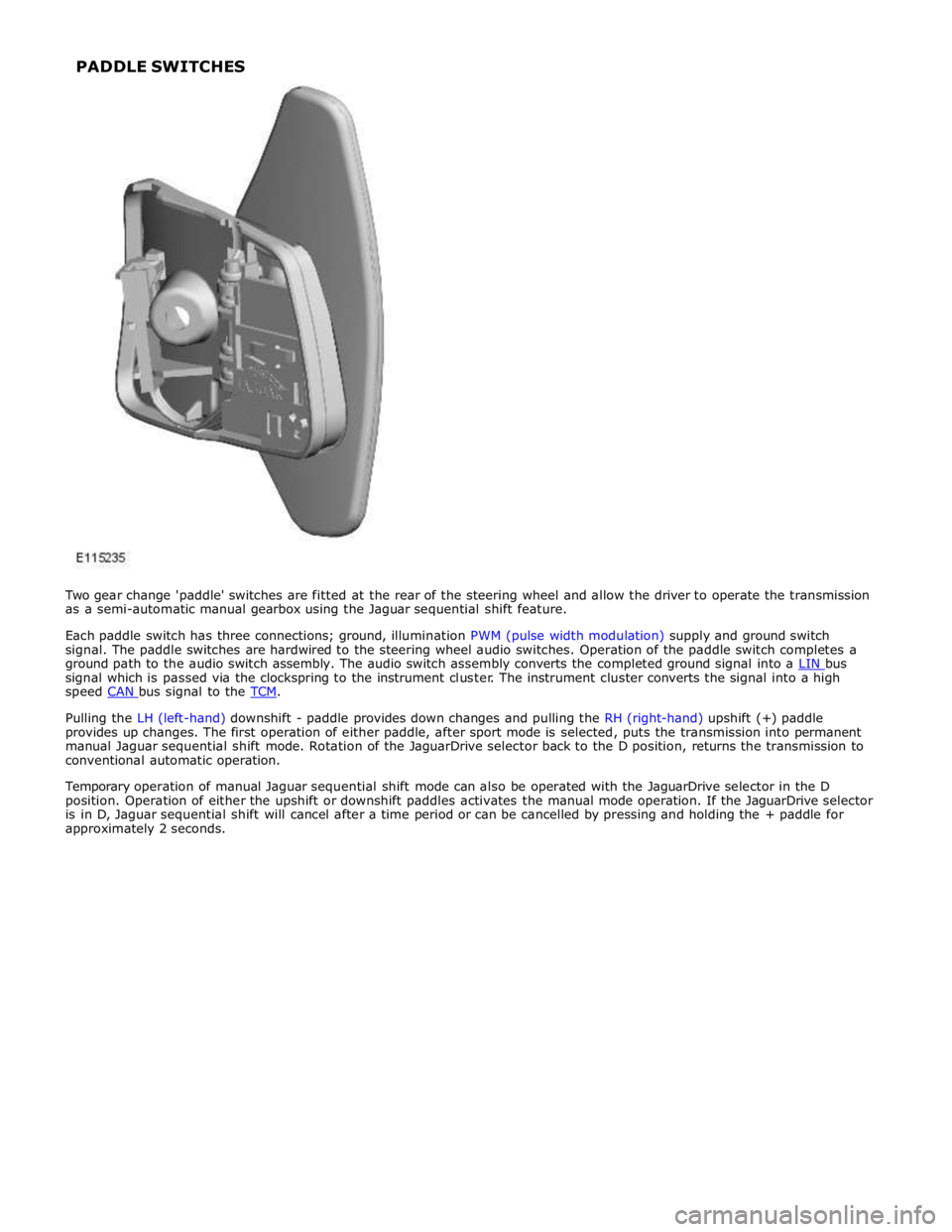
signal which is passed via the clockspring to the instrument cluster. The instrument cluster converts the signal into a high
speed CAN bus signal to the TCM.
Pulling the LH (left-hand) downshift - paddle provides down changes and pulling the RH (right-hand) upshift (+) paddle
provides up changes. The first operation of either paddle, after sport mode is selected, puts the transmission into permanent
manual Jaguar sequential shift mode. Rotation of the JaguarDrive selector back to the D position, returns the transmission to
conventional automatic operation.
Temporary operation of manual Jaguar sequential shift mode can also be operated with the JaguarDrive selector in the D
position. Operation of either the upshift or downshift paddles activates the manual mode operation. If the JaguarDrive selector
is in D, Jaguar sequential shift will cancel after a time period or can be cancelled by pressing and holding the + paddle for
approximately 2 seconds. PADDLE SWITCHES
Page 1589 of 3039
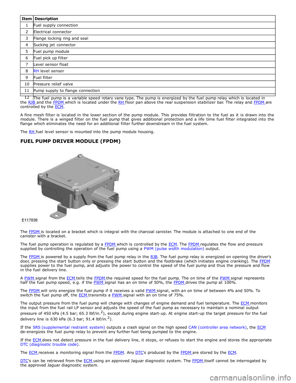
1 Fuel supply connection 2 Electrical connector 3 Flange locking ring and seal 4 Sucking jet connector 5 Fuel pump module 6 Fuel pick up filter 7 Level sensor float 8 RH level sensor 9 Fuel filter 10 Pressure relief valve 11 Pump supply to flange connection 12 The fuel pump is a variable speed rotary vane type. The pump is energized by the fuel pump relay which is located in the RJB and the FPDM which is located under the RH floor pan above the rear suspension stabilizer bar. The relay and FPDM are controlled by the ECM.
A fine mesh filter is located in the lower section of the pump module. This provides filtration to the fuel as it is drawn into the
module. There is a winged filter on the fuel pump that gives additional protection and a life time fuel filter integrated into the
flange which eliminates the need for an additional filter further downstream in the fuel system.
The RH fuel level sensor is mounted into the pump module housing.
FUEL PUMP DRIVER MODULE (FPDM)
The FPDM is located on a bracket which is integral with the charcoal canister. The module is attached to one end of the canister with a bracket.
The fuel pump operation is regulated by a FPDM which is controlled by the ECM. The FPDM regulates the flow and pressure supplied by controlling the operation of the fuel pump using a PWM (pulse width modulation) output.
The FPDM is powered by a supply from the fuel pump relay in the RJB. The fuel pump relay is energized on opening the driver's door, pressing the start button only or pressing the start button and the footbrake (which initiates engine cranking). The FPDM supplies power to the fuel pump, and adjusts the power to control the speed of the fuel pump and thus the pressure and flow
in the fuel delivery line.
A PWM signal from the ECM tells the FPDM the required speed for the fuel pump. The on time of the PWM signal represents half the fuel pump speed, e.g. if the PWM signal has an on time of 50%, the FPDM drives the pump at 100%.
The FPDM will only energize the fuel pump if it receives a valid PWM signal, with an on time of between 4% and 50%. To switch the fuel pump off, the ECM transmits a PWM signal with an on time of 75%.
The output pressure from the fuel pump will change with changes of engine demand and fuel temperature. The ECM monitors the input from the fuel rail LP sensor and adjusts the speed of the fuel pump as necessary to maintain a nominal output
pressure of 450 kPa (4.5 bar; 65.3 lbf/in.2
), except during engine start-up. At engine start-up the target pressure for the fuel
delivery line is 630 kPa (6.3 bar; 91.4 lbf/in.2
).
If the SRS (supplemental restraint system) outputs a crash signal on the high speed CAN (controller area network), the ECM de-energizes the fuel pump relay to prevent any further fuel being pumped to the engine.
If the ECM does not detect pressure in the fuel delivery line, it stops, or refuses to start the engine and stores the appropriate DTC (diagnostic trouble code).
The ECM receives a monitoring signal from the FPDM. Any DTC's produced by the FPDM are stored by the ECM.
DTC's can be retrieved from the ECM using an approved Jaguar diagnostic system. The FPDM itself cannot be interrogated by the approved Jaguar diagnostic system.
Page 1595 of 3039
Published: 28-Jul-2014
Fuel Tank and Lines - V8 5.0L Petrol/V8 S/C 5.0L Petrol - Fuel Tank and
Lines
Diagnosis and Testing
Principle of Operation
For a detailed description of the fuel tank and lines system and operation, refer to the relevant Description and Operation
section of the workshop manual. REFER to: (310-01C Fuel Tank and Lines - V8 5.0L Petrol/V8 S/C 5.0L Petrol)
Fuel Tank and Lines (Description and Operation), Fuel Tank and Lines (Description and Operation), Fuel Tank and Lines (Description and Operation).
Inspection and Verification
WARNINGS:
Eye protection must be worn at all times when working on or near any fuel related components. Failure to follow this
instruction may result in personal injury.
This procedure involves fuel handling. Be prepared for fuel spillage at all times and always observe fuel handling
precautions. Failure to follow this instruction may result in personal injury.
After carrying out repairs, the fuel system must be checked visually for leaks. This should be done after the engine has
been run, but with the engine switched OFF. Failure to follow this instruction may result in personal injury.
If taken internally, DO NOT induce vomiting. Seek immediate medical attention. Failure to follow this instruction may
result in personal injury.
If fuel contacts the eyes, flush the eyes with cold water or eyewash solution and seek medical attention. Failure to follow
this instruction may result in personal injury.
Wash hands thoroughly after handling, as prolonged contact may cause irritation. Should irritation develop, seek medical
attention. Failure to follow this instruction may result in personal injury.
CAUTIONS:
Before disconnecting any part of the system, it is imperative that all dust, dirt and debris is removed from around
components to prevent ingress of foreign matter into the fuel system. Failure to follow this instruction may result in damage to
the vehicle.
It is essential that absolute cleanliness is observed when working with these components. Always install blanking plugs
to any open orifices or lines. Failure to follow this instruction may result in damage to the vehicle.
Diagnosis by substitution from a donor vehicle is NOT acceptable. Substitution of control modules does not guarantee
confirmation of a fault, and may also cause additional faults in the vehicle being tested and/or the donor vehicle.
NOTES:
Check and rectify basic faults before beginning diagnostic routines involving pinpoint tests.
When measuring fuel sender resistance values with a multimeter, it is critical to use the correct multimeter setting. The
multimeter should not be on the 'Auto' setting and must be set to 'Manual'. This will help prevent incorrect diagnosis and
unnecessary replacement of fuel senders. If the multimeter range is set at 'Auto' then, during a sweep of the sender from 50
Ohms to 998 Ohms, the multimeter has to change its measurement range. For approximately 1 second, during the range switch
over point, the multimeter display indicates an open circuit. This can lead to a mis-diagnosis of a fuel sender fault.
1. Verify the customer concern
2. Visually inspect for obvious signs of damage and system integrity
Page 1641 of 3039
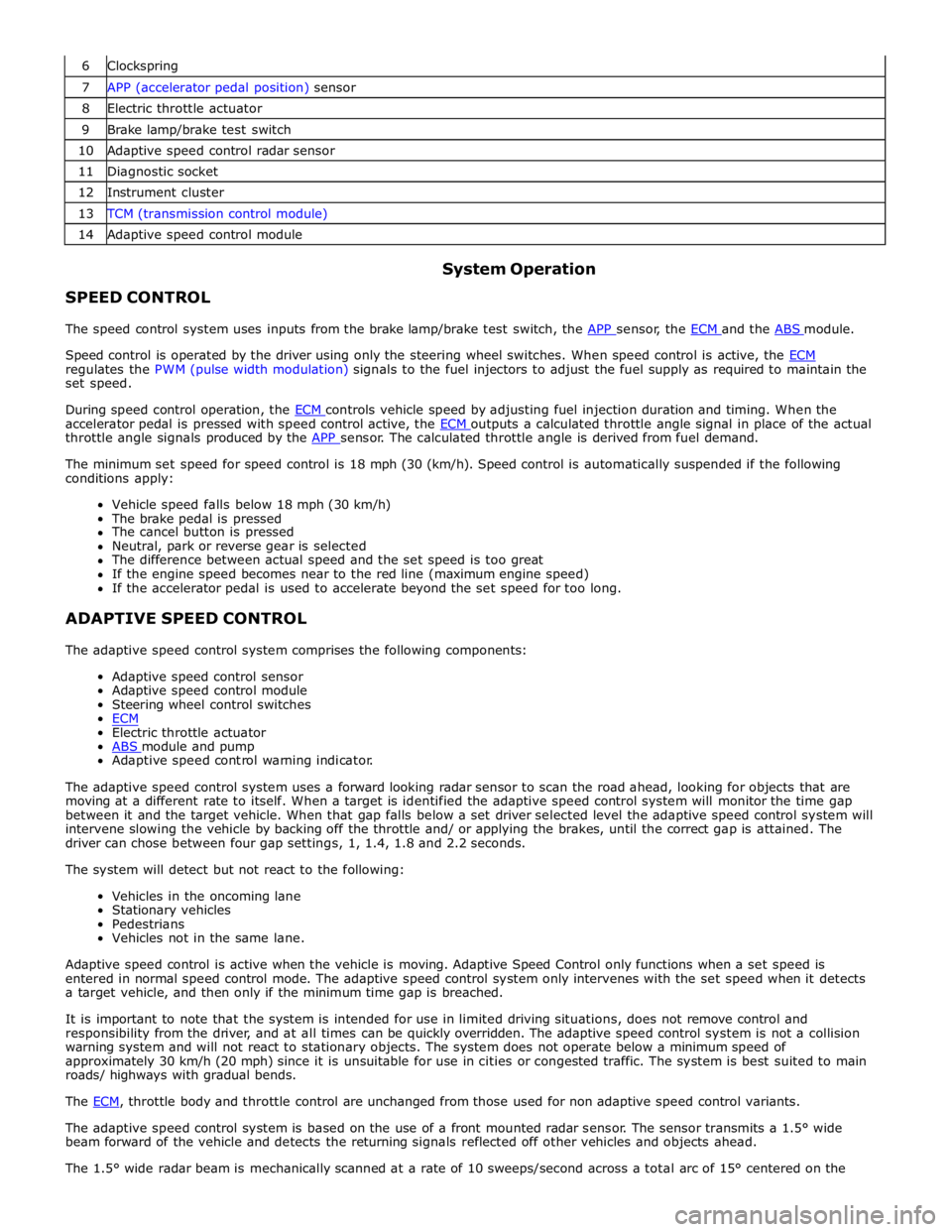
6 Clockspring 7 APP (accelerator pedal position) sensor 8 Electric throttle actuator 9 Brake lamp/brake test switch 10 Adaptive speed control radar sensor 11 Diagnostic socket 12 Instrument cluster 13 TCM (transmission control module) 14 Adaptive speed control module
SPEED CONTROL System Operation
The speed control system uses inputs from the brake lamp/brake test switch, the APP sensor, the ECM and the ABS module.
Speed control is operated by the driver using only the steering wheel switches. When speed control is active, the ECM regulates the PWM (pulse width modulation) signals to the fuel injectors to adjust the fuel supply as required to maintain the
set speed.
During speed control operation, the ECM controls vehicle speed by adjusting fuel injection duration and timing. When the accelerator pedal is pressed with speed control active, the ECM outputs a calculated throttle angle signal in place of the actual throttle angle signals produced by the APP sensor. The calculated throttle angle is derived from fuel demand.
The minimum set speed for speed control is 18 mph (30 (km/h). Speed control is automatically suspended if the following
conditions apply:
Vehicle speed falls below 18 mph (30 km/h)
The brake pedal is pressed
The cancel button is pressed
Neutral, park or reverse gear is selected
The difference between actual speed and the set speed is too great
If the engine speed becomes near to the red line (maximum engine speed)
If the accelerator pedal is used to accelerate beyond the set speed for too long.
ADAPTIVE SPEED CONTROL
The adaptive speed control system comprises the following components:
Adaptive speed control sensor
Adaptive speed control module
Steering wheel control switches
ECM
Electric throttle actuator
ABS module and pump Adaptive speed control warning indicator.
The adaptive speed control system uses a forward looking radar sensor to scan the road ahead, looking for objects that are
moving at a different rate to itself. When a target is identified the adaptive speed control system will monitor the time gap
between it and the target vehicle. When that gap falls below a set driver selected level the adaptive speed control system will
intervene slowing the vehicle by backing off the throttle and/ or applying the brakes, until the correct gap is attained. The
driver can chose between four gap settings, 1, 1.4, 1.8 and 2.2 seconds.
The system will detect but not react to the following:
Vehicles in the oncoming lane
Stationary vehicles
Pedestrians
Vehicles not in the same lane.
Adaptive speed control is active when the vehicle is moving. Adaptive Speed Control only functions when a set speed is
entered in normal speed control mode. The adaptive speed control system only intervenes with the set speed when it detects
a target vehicle, and then only if the minimum time gap is breached.
It is important to note that the system is intended for use in limited driving situations, does not remove control and
responsibility from the driver, and at all times can be quickly overridden. The adaptive speed control system is not a collision
warning system and will not react to stationary objects. The system does not operate below a minimum speed of
approximately 30 km/h (20 mph) since it is unsuitable for use in cities or congested traffic. The system is best suited to main
roads/ highways with gradual bends.
The ECM, throttle body and throttle control are unchanged from those used for non adaptive speed control variants.
The adaptive speed control system is based on the use of a front mounted radar sensor. The sensor transmits a 1.5° wide
beam forward of the vehicle and detects the returning signals reflected off other vehicles and objects ahead.
The 1.5° wide radar beam is mechanically scanned at a rate of 10 sweeps/second across a total arc of 15° centered on the
Page 1642 of 3039
longitudinal axis of the vehicle. The radar operates at millimetric wavelengths (76 - 77 GHz) and transmits a frequency
modulated continuous wave signal at a relatively low power level (no high power pulses).
With the ignition ON, the adaptive speed control module is powered up but no radar transmissions are emitted until the
vehicle is in motion.
In follow mode a set speed is selected in the normal speed control manner and this speed is maintained until a slower vehicle
is encountered in the lane ahead. When the vehicle ahead comes within the effective range of the radar sensor, the system
identifies it as a target vehicle and an icon is illuminated on the instrument cluster to indicate that the system is in "follow
mode". When the distance between the two vehicles closes to a set time gap, the adaptive speed control system closes the
throttle and if necessary applies the brakes to maintain the set time gap. Follow mode is effectively a closed loop system. If
several vehicles are ahead, the closest vehicle is chosen as the target to follow. If the target vehicle moves out of radar range,
or if either vehicle changes lane or drops below the minimum operating speed, the system exits follow mode and the follow
mode icon is extinguished. The adaptive speed control system will only raise its speed to the originally set speed, it will not
accelerate past this speed to maintain a time gap.
Driver operation of the foot brake or control switches will immediately cancel adaptive speed control.
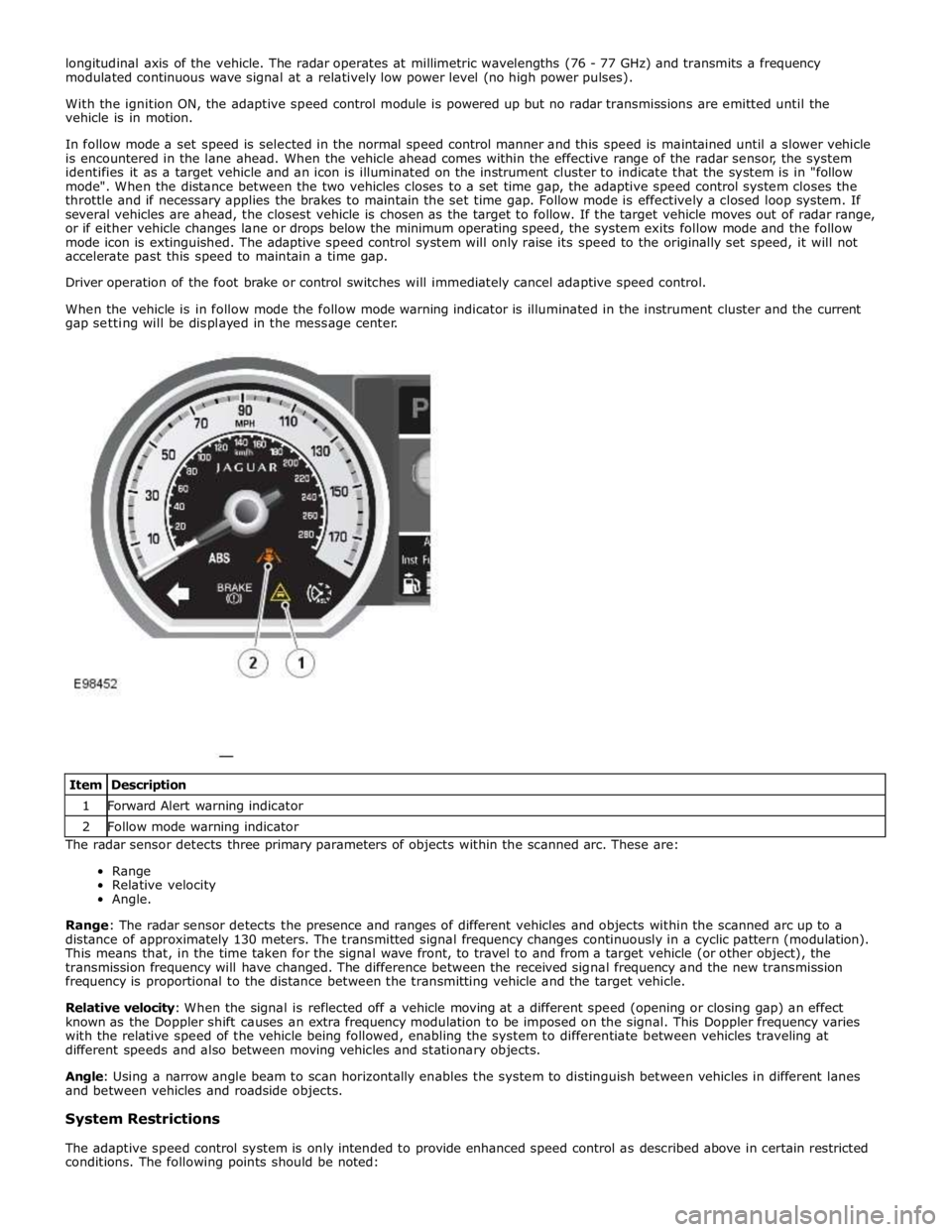
When the vehicle is in follow mode the follow mode warning indicator is illuminated in the instrument cluster and the current
gap setting will be displayed in the message center.
The radar sensor detects three primary parameters of objects within the scanned arc. These are:
Range
Relative velocity
Angle.
Range: The radar sensor detects the presence and ranges of different vehicles and objects within the scanned arc up to a
distance of approximately 130 meters. The transmitted signal frequency changes continuously in a cyclic pattern (modulation).
This means that, in the time taken for the signal wave front, to travel to and from a target vehicle (or other object), the
transmission frequency will have changed. The difference between the received signal frequency and the new transmission
frequency is proportional to the distance between the transmitting vehicle and the target vehicle.
Relative velocity: When the signal is reflected off a vehicle moving at a different speed (opening or closing gap) an effect
known as the Doppler shift causes an extra frequency modulation to be imposed on the signal. This Doppler frequency varies
with the relative speed of the vehicle being followed, enabling the system to differentiate between vehicles traveling at
different speeds and also between moving vehicles and stationary objects.
Angle: Using a narrow angle beam to scan horizontally enables the system to distinguish between vehicles in different lanes
and between vehicles and roadside objects.
System Restrictions
The adaptive speed control system is only intended to provide enhanced speed control as described above in certain restricted
conditions. The following points should be noted: Item Description 1 Forward Alert warning indicator 2 Follow mode warning indicator
Page 1647 of 3039
DTC Index
Vehicles WITH Adaptive System Installed
CAUTION: When probing connectors to take measurements in the course of the pinpoint tests, use the adaptor kit, part
number 3548-1358-00
NOTES:
If a module or component is suspect, and the vehicle remains under the Manufacturers warranty, refer to the Warranty
Policy and Procedure manual (section B1.2), or determine if any prior approval programme is in operation, prior to the
installation of a new module/component.
Generic scan tools may not read the codes listed, or may read only five digit codes. Match the five digits from the scan
tool to the first five digits of the seven digit code listed to identify the fault (the last two digits give extra information read by
the manufacturer-approved diagnostic system).
When performing voltage or resistance tests, always use a digital multimeter (DMM) accurate to three decimal places and
with a current calibration certificate. When testing resistance, always take the resistance of the DMM leads into account.
Check and rectify basic faults before beginning diagnostic routines involving pinpoint tests.
If DTCs are recorded and, after performing the pinpoint tests, a fault is not present, an intermittent concern may be the
cause. Always check for loose connections and corroded terminals.
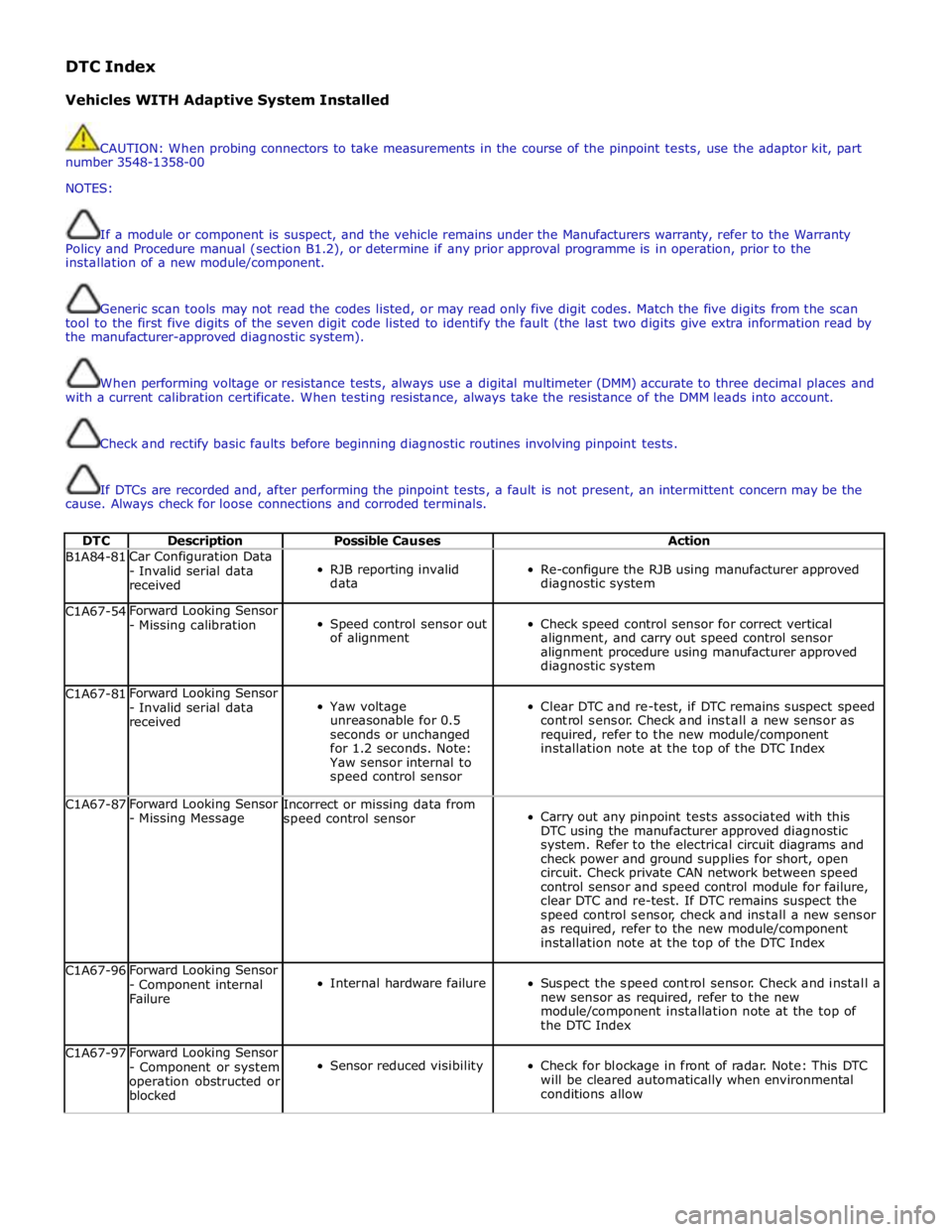
DTC Description Possible Causes Action B1A84-81 Car Configuration Data
- Invalid serial data
received
RJB reporting invalid
data
Re-configure the RJB using manufacturer approved
diagnostic system C1A67-54 Forward Looking Sensor
- Missing calibration
Speed control sensor out
of alignment
Check speed control sensor for correct vertical
alignment, and carry out speed control sensor
alignment procedure using manufacturer approved
diagnostic system C1A67-81 Forward Looking Sensor
- Invalid serial data
received
Yaw voltage
unreasonable for 0.5
seconds or unchanged
for 1.2 seconds. Note:
Yaw sensor internal to
speed control sensor
Clear DTC and re-test, if DTC remains suspect speed
control sensor. Check and install a new sensor as
required, refer to the new module/component
installation note at the top of the DTC Index C1A67-87 Forward Looking Sensor
- Missing Message Incorrect or missing data from
speed control sensor
Carry out any pinpoint tests associated with this
DTC using the manufacturer approved diagnostic
system. Refer to the electrical circuit diagrams and
check power and ground supplies for short, open
circuit. Check private CAN network between speed
control sensor and speed control module for failure,
clear DTC and re-test. If DTC remains suspect the
speed control sensor, check and install a new sensor
as required, refer to the new module/component
installation note at the top of the DTC Index C1A67-96 Forward Looking Sensor
- Component internal
Failure
Internal hardware failure
Suspect the speed control sensor. Check and install a
new sensor as required, refer to the new
module/component installation note at the top of
the DTC Index C1A67-97 Forward Looking Sensor
- Component or system
operation obstructed or
blocked
Sensor reduced visibility
Check for blockage in front of radar. Note: This DTC
will be cleared automatically when environmental
conditions allow
Page 1821 of 3039
Published: 11-May-2011
Information and Message Center - Information and Message Center - System
Operation and Component Description
Description and Operation
System Operation
SERVICE INTERVAL INDICATOR - 3.0L V6 DIESEL, 5.0L V8 SUPERCHARGER AND 5.0L V8 NATURALLY ASPIRATED ENGINES ONLY
If the vehicle is within 3,200 kilometers (1,988 miles) of a service, the message center will display 'SERVICE REQUIRED IN
XXXX km or MILES'. The display reduces the 'service required in' readout by increments every 50 kilometers (30 miles). If this
distance drops below 1 km (0.6 miles), the message center will display 'SERVICE REQUIRED'.
These messages are displayed every time the vehicle enters power mode 6, for 4 seconds after the instrument cluster bulb
check routine has finished.
NOTE: The message center will display distance to next service in miles on an instrument cluster fitted with a Miles Per
Hour (MPH) speedometer unless the driver has changed the display units on the Touch Screen Display (TSD).
Reset Procedure
To re-set the service interval indicator, the following process switch presses must each be carried out within 3 seconds:
With the vehicle in power mode 0, (ignition off) press and hold the rear fog lamp switch
Allow the vehicle to enter power mode 6 (Press the start button without a foot on the brake)
Immediately release the rear fog lamp switch
Press and hold the trip computer cycle switch
Press and hold the rear fog lamp switch
Continue to hold the trip computer and rear fog lamp switches
If the process has been successful, the message center will display 'RESETTING SERVICE MODE' and then display
'SERVICE MODE RESET' after 10 seconds
Release both switches and return the vehicle ignition to off, power mode 0.
MESSAGE CENTER Component Description
The message center LCD (liquid crystal display) display has a viewable area of 126 pixels horizontal and 174 pixels vertical. It
is divided into six information display zones as follows, starting from the top:
Set speed
Transmission position
Warning /message display
JaguarDrive Optimization icon
Odometer/Trip computer information
Fuel level.
The message center is active at all times when the ignition is on and can also be active when the ignition is off, dependant on
the information to be displayed. The message center LCD illumination is controlled by the sun load light sensor located on the instrument panel. In bright conditions, the illumination is set to maximum brightness. As the ambient light levels drop, the
illumination dims. When the lights are switched on or activated by the 'AUTO' function, the illumination operates in the same
way until a defined ambient light threshold is reached, at this point the setting of the panel illumination dimmer in the
auxiliary light switch will control the brightness.
If more than one message is active, each message is displayed for 4 seconds in the order of priority. Once all messages have
been displayed, they are again displayed in turn for 2 seconds each. Warning messages can be displayed when the ignition is
in accessory power mode 4 which is the initial ignition state when a door is opened.
Message Priority
Messages are assigned priorities which are defined by the effect on driving safety and functional ability of the vehicle. When
new messages are displayed they may be accompanied by a chime from the instrument cluster sounder. A new message will be
displayed immediately, providing the currently displayed message (if there is one) has been displayed for at least 4 seconds. A
warning indicator will be activated simultaneously with the message being displayed. If more than one fault warning message
is being displayed, the messages will cycle, in priority order, with each message being displayed for 2 seconds.
INFORMATION DISPLAY
The transmission display is located in the upper section of the LCD. The transmission position information is sent from the TCM (transmission control module) in a high speed CAN (controller area network) message to the instrument cluster. The
transmission has three modes of operation:
Conventional automatic operation (JaguarDrive selector in 'D' position)
Sport automatic operation (JaguarDrive selector in 'S' position)
Manual gear operation - Jaguar Sequential Shift.