2010 JAGUAR XFR change time
[x] Cancel search: change timePage 1822 of 3039
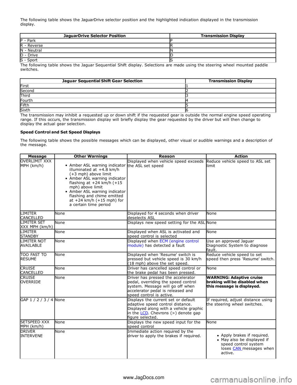
The following table shows the JaguarDrive selector position and the highlighted indication displayed in the transmission
display.
JaguarDrive Selector Position Transmission Display P - Park P R - Reverse R N - Neutral N D - Drive D S - Sport S The following table shows the Jaguar Sequential Shift display. Selections are made using the steering wheel mounted paddle
switches.
Jaguar Sequential Shift Gear Selection Transmission Display First 1 Second 2 Third 3 Fourth 4 Fifth 5 Sixth 6 The transmission may inhibit a requested up or down shift if the requested gear is outside the normal engine speed operating
range. If this occurs, the transmission display will briefly display the gear requested by the driver but will then change to
display the actual gear selection.
Speed Control and Set Speed Displays
The following table shows the possible messages which can be displayed, other visual or audible warnings and a description of
the message.
Message Other Warnings Reason Action OVERLIMIT XXX
MPH (km/h)
Amber ASL warning indicator
illuminated at +4.8 km/h
(+3 mph) above limit
Amber ASL warning indicator
flashing at +24 km/h (+15
mph) above limit
Amber ASL warning indicator
flashing and chime emitted
at +24 km/h (+15 mph) for
a certain time period Displayed when vehicle speed exceeds
the ASL set speed Reduce vehicle speed to ASL set
limit LIMITER
CANCELLED None
Displayed for 4 seconds when driver
deselects ASL None LIMITER SET
XXX MPH (km/h) None Displays new speed setting for the ASL None LIMITER
STANDBY None
Displayed when ASL is activated and speed control is selected None LIMITER NOT
AVAILABLE None
Displayed when ECM (engine control
module) has detected a fault Use an approved Jaguar
Diagnostic System to diagnose
fault. TOO FAST TO
RESUME None
Displayed when 'Resume' switch is
pressed but vehicle speed is 30 km/h (18 mph) above the set speed. Reduce vehicle speed to set
speed then press 'Resume' switch. CRUISE
CANCELLED None
Driver has cancelled speed control or
the brake pedal has been pressed. None CRUISE
OVERRIDE None
Driver has pressed the accelerator
pedal, overriding the speed control
system. Message will go off when
accelerator pedal is released and speed control is active. WARNING: Adaptive cruise
braking will be disabled when
this message is displayed. GAP 1 / 2 / 3 / 4 None
Displays the current set or default
adaptive speed control distance.
Displayed along with a vehicle graphic
in the LCD. Chevrons (>) denote gap figure selected. If required, adjust distance using
the steering wheel switches. SETSPEED XXX
MPH (km/h) None
Displays the new speed input for the speed control None DRIVER
INTERVENE None
Immediate action required by the
driver to apply the brakes if required.
Apply brakes if required.
May also be displayed if
speed control system
loses CAN messages when active. www.JagDocs.com
Page 1823 of 3039
Message Other Warnings Reason Action CRUISE NOT
AVAILABLE None Speed control cannot be engaged.
A fault has occurred in the speed
control system. Diagnose fault
using an approved Jaguar Diagnostic System. RADAR SENSOR
BLOCKED None
The adaptive speed control radar
sensor has become dirty or obstructed. Remove obstruction or clean the
radar sensor. FORWARD ALERT
OFF None
Forward alert has been switched off.
No warning will be given for objects in
the vehicles forward direction. None FORWARD ALERT None
Forward alert has been switched on or
the gap settings have changed. None FORWARD ALERT
UNAVAILABLE None
Forward Alert and Emergency Brake
Assist are not available. Use an approved Jaguar
Diagnostic System to diagnose
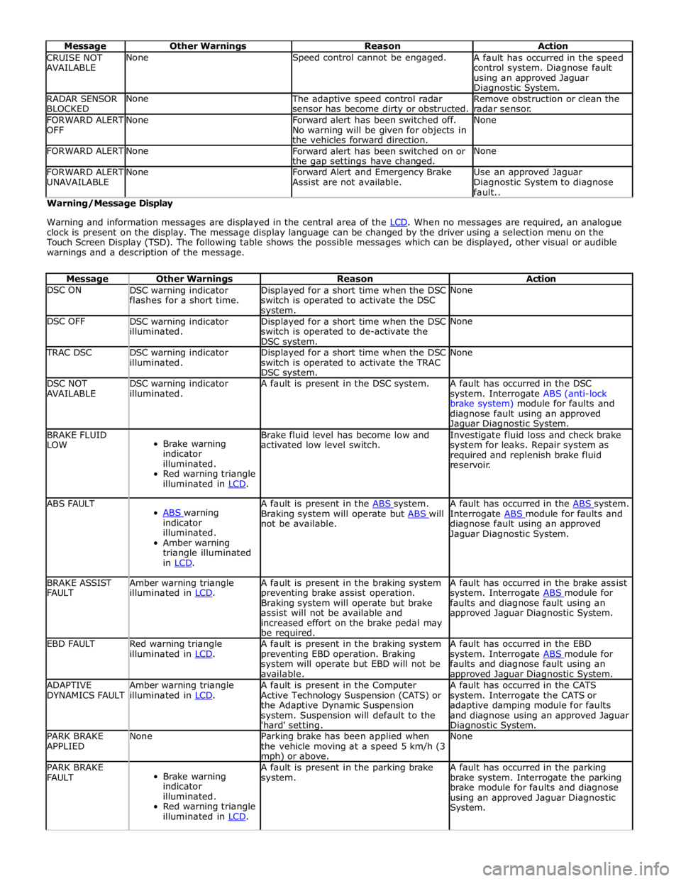
fault.. Warning/Message Display
Warning and information messages are displayed in the central area of the LCD. When no messages are required, an analogue clock is present on the display. The message display language can be changed by the driver using a selection menu on the
Touch Screen Display (TSD). The following table shows the possible messages which can be displayed, other visual or audible
warnings and a description of the message.
Message Other Warnings Reason Action DSC ON
DSC warning indicator
flashes for a short time. Displayed for a short time when the DSC
switch is operated to activate the DSC system. None DSC OFF
DSC warning indicator
illuminated. Displayed for a short time when the DSC
switch is operated to de-activate the
DSC system. None TRAC DSC
DSC warning indicator
illuminated. Displayed for a short time when the DSC
switch is operated to activate the TRAC
DSC system. None DSC NOT
AVAILABLE DSC warning indicator
illuminated. A fault is present in the DSC system.
A fault has occurred in the DSC
system. Interrogate ABS (anti-lock
brake system) module for faults and
diagnose fault using an approved Jaguar Diagnostic System. BRAKE FLUID
LOW
Brake warning
indicator
illuminated.
Red warning triangle
illuminated in LCD. Brake fluid level has become low and
activated low level switch. Investigate fluid loss and check brake
system for leaks. Repair system as
required and replenish brake fluid
reservoir. ABS FAULT
ABS warning indicator
illuminated.
Amber warning
triangle illuminated
in LCD. A fault is present in the ABS system. Braking system will operate but ABS will not be available. A fault has occurred in the ABS system. Interrogate ABS module for faults and diagnose fault using an approved
Jaguar Diagnostic System. BRAKE ASSIST
FAULT Amber warning triangle
illuminated in LCD. A fault is present in the braking system
preventing brake assist operation.
Braking system will operate but brake
assist will not be available and
increased effort on the brake pedal may
be required. A fault has occurred in the brake assist
system. Interrogate ABS module for faults and diagnose fault using an
approved Jaguar Diagnostic System. EBD FAULT
Red warning triangle
illuminated in LCD. A fault is present in the braking system
preventing EBD operation. Braking
system will operate but EBD will not be
available. A fault has occurred in the EBD
system. Interrogate ABS module for faults and diagnose fault using an approved Jaguar Diagnostic System. ADAPTIVE
DYNAMICS FAULT Amber warning triangle
illuminated in LCD. A fault is present in the Computer
Active Technology Suspension (CATS) or
the Adaptive Dynamic Suspension
system. Suspension will default to the
'hard' setting. A fault has occurred in the CATS
system. Interrogate the CATS or
adaptive damping module for faults
and diagnose using an approved Jaguar Diagnostic System. PARK BRAKE
APPLIED None
Parking brake has been applied when
the vehicle moving at a speed 5 km/h (3 mph) or above. None PARK BRAKE
FAULT
Brake warning
indicator
illuminated.
Red warning triangle
illuminated in LCD. A fault is present in the parking brake
system. A fault has occurred in the parking
brake system. Interrogate the parking
brake module for faults and diagnose
using an approved Jaguar Diagnostic
System.
Page 1826 of 3039
Message Other Warnings Reason Action expansion tank to maximum
level.
If message re-appears,
investigate coolant system for
leakage. BLIND SPOT
MONITOR NOT
AVAILABLE Amber warning triangle
illuminated LCD. Blind spot monitoring system has a fault
or vehicle speed is below threshold for system operation. Drive vehicle above threshold speed or
investigate cause of fault. BLIND SPOT
MONITOR
SENSOR
BLOCKED Amber warning triangle
illuminated LCD. A blind spot monitoring sensor has
become dirty or obstructed. Remove obstruction or clean the radar
sensor. BRAKE PADS
LOW Amber warning triangle
illuminated LCD. Brake pads have reached the service
limit. Replace brake pads. SERVICE
REQUIRED IN
XXXX MILES/km Amber warning triangle
illuminated LCD. If the vehicle is within 3,200 kilometers
(1,988 miles) of a service, the message
center will display this message. The
displayed distance will decrease in
increments of 50 km (31 miles). None SERVICE
REQUIRED Amber warning triangle
illuminated LCD. This is displayed if the distance to next
service drops below 1 km (0.6 miles). Vehicle requires service. RESETTING
SERVICE MODE Amber warning triangle
illuminated LCD. Displayed during the service reset procedure. None SERVICE MODE
RESET Amber warning triangle
illuminated LCD. Displayed when the service rest procedure has been successful. None WINTER MODE
CONFIRMED Snow mode symbol
illuminated LCD. Displayed when snow mode has been
selected. None DYNAMIC MODE
CONFIRMED Dynamic mode symbol
illuminated LCD. Displayed when dynamic mode has been
selected. None MODE CHANGE
IN PROGRESS None or Snow mode symbol
illuminated or Dynamic
mode symbol illuminated
LCDLCD Displayed when the driver has selected
an alternative JaguarDrive mode. None RECOMMEND
WINTER MODE
FOR CONDITIONS None or Dynamic mode
symbol illuminated LCD Displayed when the JaguarDrive senses
excessive wheel slip. Select winter mode. WINTER MODE
OFF None
Confirmation that winter mode has been
deselected. None DYNAMIC MODE
OFF None
Confirmation that dynamic mode has
been deselected. None WINTER MODE
FAULT Amber warning triangle
illuminated LCD. A sub-system fault is present and the
driver attempts to select a different
JaguarDrive Control mode. The message
'WINTER MODE FAULT' can also in very
rare circumstances be generated by a
fault in the JaguarDrive Control module. Investigate cause of message.
Interrogate sub-system control
modules for faults and diagnose using
an approved Jaguar Diagnostic System.
If no sub-system fault is found,
investigate JaguarDrive Control
module. DYNAMIC MODE
FAULT Amber warning triangle
illuminated LCD. A sub-system fault is present and the
driver attempts to select a different
JaguarDrive Control mode. The message
'DYNAMIC MODE FAULT' can also, in very
rare circumstances, be generated by a
fault in the JaguarDrive Control module. Investigate cause of message.
Interrogate sub-system control
modules for faults and diagnose using
an approved Jaguar Diagnostic System.
If no sub-system fault is found,
investigate JaguarDrive Control
module. SPECIAL MODES
NOT AVAILABLE Amber warning triangle
illuminated LCD. A sub-system fault is present and the
driver attempts to select a different
JaguarDrive Control mode. The message
'SPECIAL MODES NOT AVAILABLE' can
also in very rare circumstances be
generated by a fault in the JaguarDrive
Control module. Investigate cause of message.
Interrogate sub-system control
modules for faults and diagnose using
an approved Jaguar Diagnostic System.
If no sub-system fault is found,
investigate JaguarDrive Control
module. LISTENING Tone emitted from the
instrument cluster. The voice button has been pressed and
the Jaguar voice system is active and awaiting a voice command. None VOICE NOT
READY None
If the Voice button on the steering
wheel is pressed before the system is
ready to receive a command, VOICE NOT
READY will be displayed Press button a second time after a
short delay. INSERT MAP DISC None Navigation disc not loaded.
Load navigation disc in the navigation
computer. NOT AVAILABLE
PHONE IN USE None
Voice button has been pressed during a telephone call. None COMMAND NOT
RECOGNISED None
Jaguar Voice system has not recognised
the command. Repeat the command speaking clearly.
Page 1829 of 3039
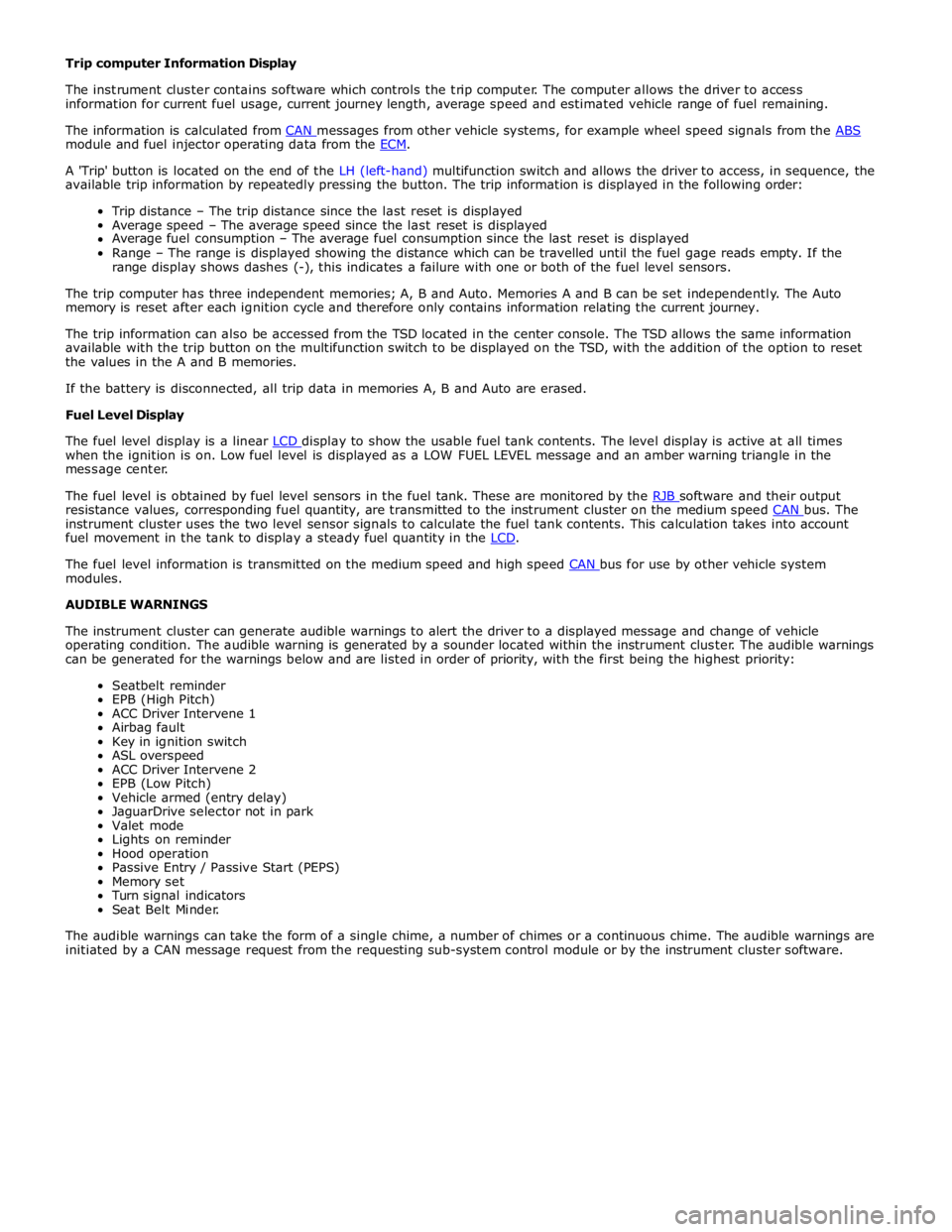
module and fuel injector operating data from the ECM.
A 'Trip' button is located on the end of the LH (left-hand) multifunction switch and allows the driver to access, in sequence, the
available trip information by repeatedly pressing the button. The trip information is displayed in the following order:
Trip distance – The trip distance since the last reset is displayed
Average speed – The average speed since the last reset is displayed
Average fuel consumption – The average fuel consumption since the last reset is displayed
Range – The range is displayed showing the distance which can be travelled until the fuel gage reads empty. If the
range display shows dashes (-), this indicates a failure with one or both of the fuel level sensors.
The trip computer has three independent memories; A, B and Auto. Memories A and B can be set independently. The Auto
memory is reset after each ignition cycle and therefore only contains information relating the current journey.
The trip information can also be accessed from the TSD located in the center console. The TSD allows the same information
available with the trip button on the multifunction switch to be displayed on the TSD, with the addition of the option to reset
the values in the A and B memories.
If the battery is disconnected, all trip data in memories A, B and Auto are erased.
Fuel Level Display
The fuel level display is a linear LCD display to show the usable fuel tank contents. The level display is active at all times when the ignition is on. Low fuel level is displayed as a LOW FUEL LEVEL message and an amber warning triangle in the
message center.
The fuel level is obtained by fuel level sensors in the fuel tank. These are monitored by the RJB software and their output resistance values, corresponding fuel quantity, are transmitted to the instrument cluster on the medium speed CAN bus. The instrument cluster uses the two level sensor signals to calculate the fuel tank contents. This calculation takes into account
fuel movement in the tank to display a steady fuel quantity in the LCD.
The fuel level information is transmitted on the medium speed and high speed CAN bus for use by other vehicle system modules.
AUDIBLE WARNINGS
The instrument cluster can generate audible warnings to alert the driver to a displayed message and change of vehicle
operating condition. The audible warning is generated by a sounder located within the instrument cluster. The audible warnings
can be generated for the warnings below and are listed in order of priority, with the first being the highest priority:
Seatbelt reminder
EPB (High Pitch)
ACC Driver Intervene 1
Airbag fault
Key in ignition switch
ASL overspeed
ACC Driver Intervene 2
EPB (Low Pitch)
Vehicle armed (entry delay)
JaguarDrive selector not in park
Valet mode
Lights on reminder
Hood operation
Passive Entry / Passive Start (PEPS)
Memory set
Turn signal indicators
Seat Belt Minder.
The audible warnings can take the form of a single chime, a number of chimes or a continuous chime. The audible warnings are
initiated by a CAN message request from the requesting sub-system control module or by the instrument cluster software.
Page 1846 of 3039
signal to a digital signal by the sensor. The digital signal is passed to the parking aid module and compared with
pre-programmed data stored in an EEPROM (electrically erasable programmable read only memory) within the module. The
module receives this data via the signal line from the sensor and calculates the distance from the object using the elapsed
time between the transmitted and received impulse. The duration of the impulse duration is determined by the module, with
the sensor controlling the frequency of the impulse output.
In receiver mode, the sensor receives impulses that were emitted by adjacent sensors. The module uses this information to
precisely determine the position and distance of the object.
If no objects are detected there are no further warning tones. If an object is detected, repeated audible tones are emitted
from either the front or rear audio speakers as appropriate. The time delay between the tones decreases as the distance
between the object and the vehicle decreases, until at approximately 300 mm (12 inches), the audible tone becomes
continuous.
After the initial detection of an object, if there is no decrease in the distance between an object and the central sensors, the
time delay between the audible warnings remains constant. If an object is detected by one of the corner sensors only, the
audible warnings stop after approximately 5 seconds if there is no change in the distance between an object and the corner
sensor.
When approaching several objects within detection range, the control module recognises the distance from the vehicle to the
nearest object.
The PDC module will prioritise the objects detected, the nearest object detected will take priority and the corresponding audio
outputs will be emitted. For example if 2 objects are detected (one front one rear) the nearest detected object will take
priority and relevant audible tone will be heard.
If two objects are detected at equal distance (one front one rear) the audible tones will alternate between the front and rear
speakers.
If reverse (R) is the first gear selected after the ignition is switched on, both the front (if fitted) and rear parking aid sensors
will become operational. If a forward drive gear is subsequently selected, the front and rear parking aid sensors will remain
operational until vehicle speed increases above 16 km/h (10 mph), park (P) is selected or the PDC control switch is pressed.
If drive (D) is the first gear selected after the ignition is switched on the parking aid system will have to be activated by
pressing the PDC control switch.
NOTE: The PDC system can not be activated whilst the vehicle is in park (P).
The volume output of the parking aid audible tones can be adjusted by selecting the 'Vehicle Settings' menu and selecting
'Parking' from the menu on the TSD. The volume can be adjusted using the + or - selections on the TSD.
The system can detect when a trailer is connected to the vehicle by a message output on the medium speed CAN bus from the trailer module. When the parking aid module detects that a trailer is connected to the vehicle, the rear sensors are disabled to
prevent constant warnings due to the close proximity of the trailer.
NOTE: The ignition needs to be cycled once the trailer has been disconnected to activate the rear parking aid system.
Page 1882 of 3039
11 Secondary battery 12 Dual Battery Junction Box (DBJB) 13 Rear Junction Box (RJB) 14 Megafuse 15 Battery Junction box (BJB) 16 Primary battery
System Operation BATTERY MONITORING SYSTEM - TD4 2.2L DIESEL VEHICLES ONLY
Periodically the battery monitoring system module will instigate a self-calibration routine. To self calibrate, the battery
monitoring system first charges the battery to its full condition.
NOTE: If the vehicle is only driven for short periods the charging process could take a number of days to complete.
Once the battery is fully charged, the battery monitoring system will discharge the battery to approximately 75% of its full
state of charge, but never lower than 12.2 V. The time taken to complete this part of the routine is dependent on the electrical
load on the vehicle.
When the second part of the routine has been successfully completed, the battery monitoring system will return the battery to
its optimum level of charge. The optimum level of charge will be between 12.6 V and 15 V, depending on battery condition,
temperature and loading.
The battery monitoring system module also monitors the battery condition with the engine switched off. If a low voltage
condition is detected the module can request the infotainment system is switched off to protect battery voltage. Once the
infotainment system has been switched off, the vehicle must be run for at least 5 minutes to charge the battery before the
infotainment system can be operated with the engine switched off.
BATTERY MONITORING SYSTEM - SINGLE AND DUAL BATTERY SYSTEM VEHICLES
When the ignition is off (power mode 0), the BMS control module records the primary battery state of charge and begins to
monitor the battery condition from this point.
If the battery state of charge falls by 7%, the BMS control module will monitor the primary battery for 5 minutes. If after the 5
minute monitoring period, the primary battery charge has continued to fall due to the quiescent drain current being too high,
the BMS control module will determine that some control modules are still 'awake'. The BMS control module sends a shutdown
message on the LIN (local interconnect network) bus to the GWM (Gateway Module). The GWM sends a CAN (controller area
network) bus message on both the medium and high speed networks to all control modules, requesting them to shutdown.
The BMS control module will monitor the primary battery state of charge for a further 5 minutes and determine if the primary
battery state of charge is still dropping. If a quiescent drain current continues, the primary battery state of charge will
continue to drop. If the state of charge falls to 12% of the initial monitoring value, the BMS control module determines that
one or more control modules are still awake and a failure to respond to the shutdown request may indicate an error state
within the control module(s).
BMS Low Battery Warning and Energy Management Messages
The BMS continuously monitors the condition of the primary vehicle battery. If excessive battery discharge occurs, the system
will begin to shut down non-essential electrical systems in order to protect the battery.
If the BMS calculates that battery condition is not within set parameters, there are 3 messages that can be displayed, 2 on the
touch screen and 1 on the message center. These inform the user that the battery is either at a low level of charge or the
engine-off power consumption limit has been exceeded.
Low Battery - Please switch engine on or system will shutdown in 3 minutes: is displayed as a Warning on the
touch screen if the engine is not running. This indicates that the battery has fallen below a predefined threshold. As
soon as the battery is charged back above this threshold then the message will be removed.
Low Battery - Please start your engine is displayed on the message center if the engine is not running. This indicates
that the battery has fallen below a predefined threshold. As soon as the battery is charged back above this threshold
then the message will be removed or it can be manually removed by pressing 'OK'.
System will shut down in 3 minutes: is displayed as an Energy management on the touch screen if the engine is not
running, and system features are causing excessive battery discharge. After 3 minutes the BMS will begin shutting
down vehicle systems. Normal system operation will resume when the engine is started.
This is based on a percentage of battery capacity available for the customer to use with the engine off. The percentage can
change based upon several factors.
Once triggered, the resetting of this message will not occur until the vehicle is driven for 10 minutes with the engine running
(to allow the battery to recoup any lost charge). However, if the engine is run for less than 10 minutes, the message will only
be displayed after an additional 5 minutes with the ignition on but engine off.
BMS Control Module Self Calibration
Periodically the BMS control module will instigate a self-calibration routine. To self calibrate, the battery monitoring system www.JagDocs.com
Page 1883 of 3039
first charges the battery to its full condition.
NOTE: If the vehicle is only driven for short periods the charging process could take a number of days to complete.
Once the battery is fully charged, the BMS control module will discharge the battery to approximately 75% of its full state of
charge, but never lower than 12.2 V. The time taken to complete this part of the routine is dependent on the electrical load on
the vehicle.
When the second part of the routine has been successfully completed, the BMS control module will return the battery to its
optimum level of charge. The optimum level of charge will be between 12.6 V and 15 V, depending on battery condition,
temperature and loading.
The BMS control module also monitors the primary battery condition with the engine switched off. If a low voltage condition is
detected the BMS control module can request the infotainment system is switched off to protect battery voltage.
DUAL BATTERY SYSTEM - DUAL BATTERY SYSTEM VEHICLES ONLY
The dual battery system prevents electrical loads on the vehicle being subjected to low voltage levels during an ECO
(stop/start system) engine start. Low voltage can occur due to the power demand of the TSS (Tandem Solenoid Starter) motor
and could result in degraded performance of components and/or system control modules. The GWM contains the software to
control the dual battery system and electrical load management system to ensure that ECO engine starts do not affect other
vehicle systems.
The dual battery system isolates all power supply sensitive electrical components which may be affected by low voltage from
the primary battery due TSS motor operation, and supplies them with power from the secondary battery when an engine start
is in progress.
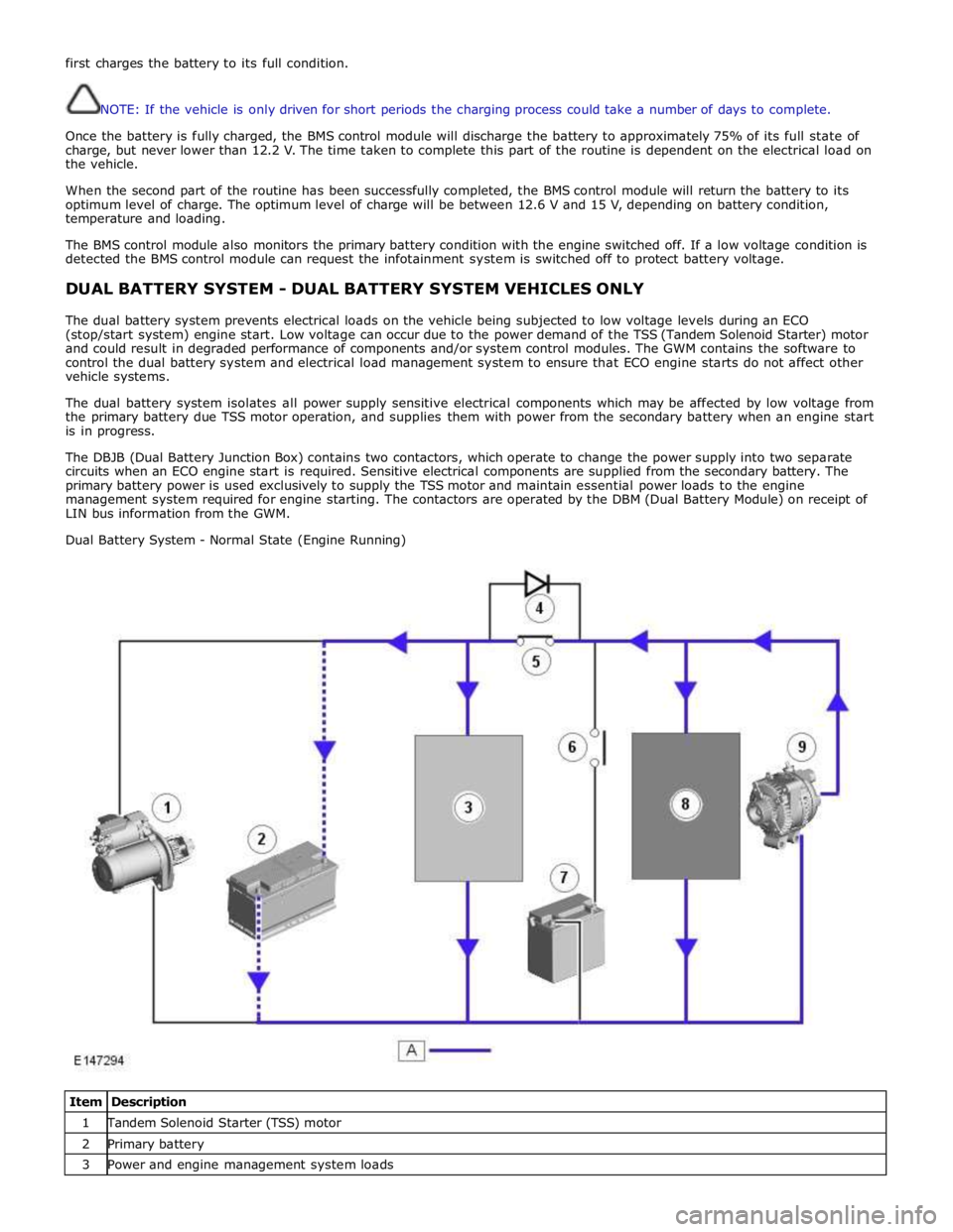
The DBJB (Dual Battery Junction Box) contains two contactors, which operate to change the power supply into two separate
circuits when an ECO engine start is required. Sensitive electrical components are supplied from the secondary battery. The
primary battery power is used exclusively to supply the TSS motor and maintain essential power loads to the engine
management system required for engine starting. The contactors are operated by the DBM (Dual Battery Module) on receipt of
LIN bus information from the GWM.
Dual Battery System - Normal State (Engine Running)
Item Description 1 Tandem Solenoid Starter (TSS) motor 2 Primary battery 3 Power and engine management system loads
Page 1886 of 3039
the secondary battery (if fitted) and passes through a grommet in the floorpan.
On new vehicles the primary battery positive terminal is fitted with a transit relay. The transit relay must removed using the
correct process detailed in the Pre Delivery Inspection (PDI) manual.
The battery negative terminal is fitted with a BMS control module. The control module is integral with the battery negative
cable and communicates with the GWM via a LIN bus connection. The battery condition information is passed to the GWM
which controls the generator output accordingly.
CAUTION: To avoid damage to the BMS control module, always use the body ground point in the engine compartment and
not the battery negative terminal when connecting a slave power supply.
Failure to use the recommended ground point will lead to the setting of a DTC. Incorrect information of battery condition will
be retained by the BMS control module due to the unmonitored current flow into the battery. The system will however,
recognize and compensate for the change in battery status after a period of time.
If a new battery is fitted, the BMS control module will require re-calibration using a Jaguar approved diagnostic system.
Replacement of the BMS control module requires no action as the control module will re-calibrate automatically.
SECONDARY BATTERY - DUAL BATTERY VEHICLES ONLY
The secondary battery is located in a tray on the next of the primary battery and is secured to the DBJB with a bracket. The
battery negative (-) terminal is connected via a cable to the vehicle body. The positive (+) terminal is connected by a cable to
the DBJB. The battery is vented via a tube which is connected with a T piece to the vent from the primary battery and passes
through a grommet in the floorpan.
The state of charge of the secondary battery is monitored by the Gateway Module (GWM).
BATTERY MONITORING SYSTEM (BMS)
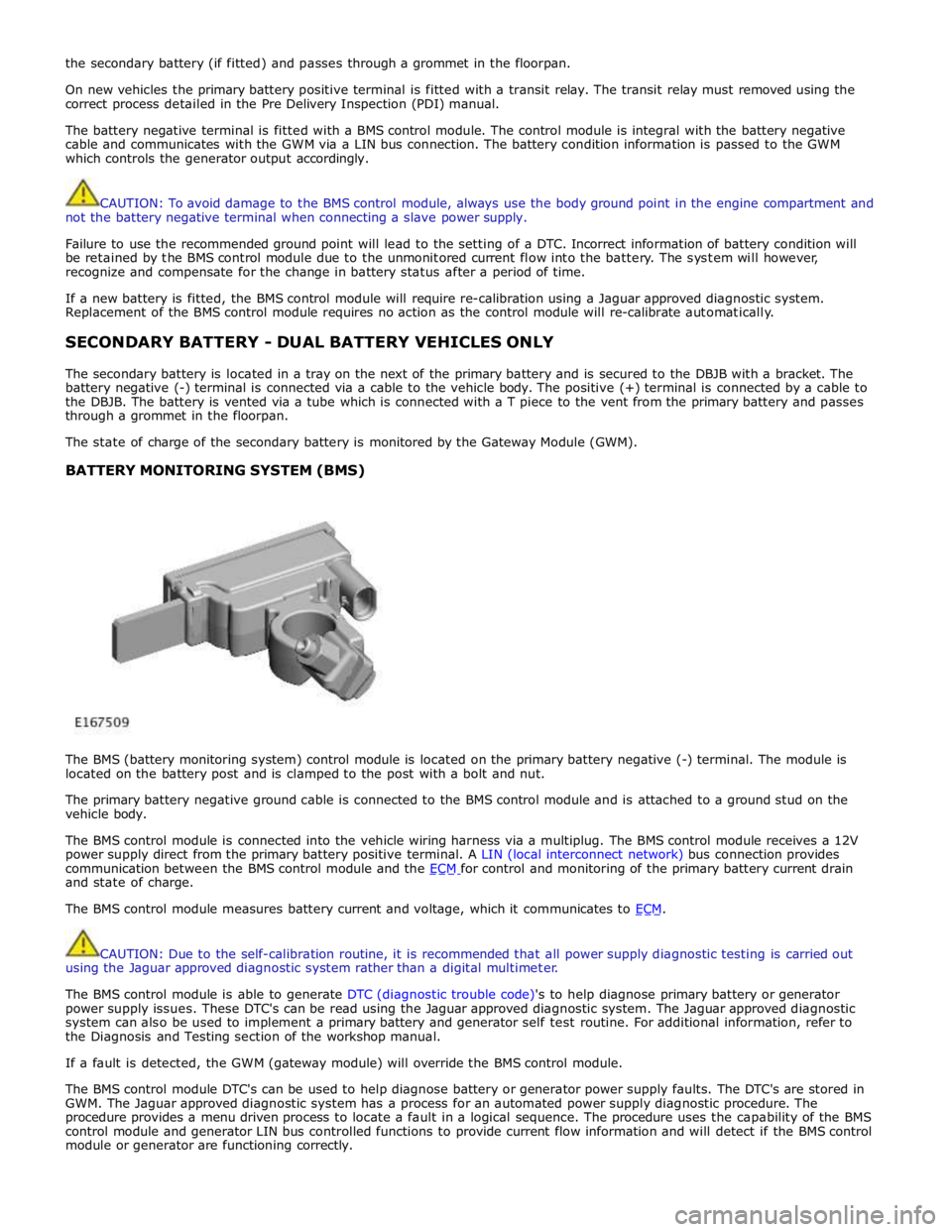
The BMS (battery monitoring system) control module is located on the primary battery negative (-) terminal. The module is
located on the battery post and is clamped to the post with a bolt and nut.
The primary battery negative ground cable is connected to the BMS control module and is attached to a ground stud on the
vehicle body.
The BMS control module is connected into the vehicle wiring harness via a multiplug. The BMS control module receives a 12V
power supply direct from the primary battery positive terminal. A LIN (local interconnect network) bus connection provides
communication between the BMS control module and the ECM for control and monitoring of the primary battery current drain and state of charge.
The BMS control module measures battery current and voltage, which it communicates to ECM.
CAUTION: Due to the self-calibration routine, it is recommended that all power supply diagnostic testing is carried out
using the Jaguar approved diagnostic system rather than a digital multimeter.
The BMS control module is able to generate DTC (diagnostic trouble code)'s to help diagnose primary battery or generator
power supply issues. These DTC's can be read using the Jaguar approved diagnostic system. The Jaguar approved diagnostic
system can also be used to implement a primary battery and generator self test routine. For additional information, refer to
the Diagnosis and Testing section of the workshop manual.
If a fault is detected, the GWM (gateway module) will override the BMS control module.
The BMS control module DTC's can be used to help diagnose battery or generator power supply faults. The DTC's are stored in
GWM. The Jaguar approved diagnostic system has a process for an automated power supply diagnostic procedure. The
procedure provides a menu driven process to locate a fault in a logical sequence. The procedure uses the capability of the BMS
control module and generator LIN bus controlled functions to provide current flow information and will detect if the BMS control
module or generator are functioning correctly.