Page 403 of 3039
Interior Trim and Ornamentation, Removal and Installation).
Vehicles with active damping
2. Disconnect the active suspension damper electrical connector.
All vehicles
3. Remove the shock absorber and spring assembly top mount
nuts. TORQUE: 28 Nm
4. WARNING: Make sure to support the vehicle with axle stands.
Raise the vehicle.
5. Remove the wheel and tire.
For additional information, refer to: Wheel and Tire (204-04 Wheels and Tires, Removal and Installation).
Page 408 of 3039
Interior Trim and Ornamentation, Removal and Installation). Vehicleswithactivedamping
Page 474 of 3039
Published: 11-May-2011
Wheels and Tires - Tire Pressure Monitoring System (TPMS) Module
Removal and Installation
Removal
NOTE: Removal steps in this procedure may contain installation details.
1. Switch the igntion off.
2. Remove the right-hand front seat.
Refer to: Front Seat (501-10 Seating, Removal and Installation).
3. Refer to: B-Pillar Lower Trim Panel (501-05 Interior Trim and Ornamentation, Removal and Installation).
4. Detach and reposition the floor covering.
5. www.JagDocs.com
Page 489 of 3039
Vehicle Dynamic Suspension - Adaptive Damping Module
Removal and Installation
Removal
NOTE: Removal steps in this procedure may contain installation details. Published: 11-May-2011
1. Refer to: Front Seat (501-10 Seating, Removal and Installation).
2. Refer to: B-Pillar Lower Trim Panel (501-05 Interior Trim and Ornamentation, Removal and Installation).
3. Detach and reposition the floor covering.
4.
5. www.JagDocs.com
Page 492 of 3039
Published: 11-May-2011
Vehicle Dynamic Suspension - Rear Suspension Vertical Accelerometer
Removal and Installation
Removal
NOTE: Removal steps in this procedure may contain installation details.
1. Refer to: Loadspace Trim Panel LH (501-05 Interior Trim and Ornamentation, Removal and Installation).
Installation
2. CAUTION: The accelerometer is an extremely delicate
component and can easily be rendered unserviceable. Never
use an accelerometer which has been dropped or subjected
to mistreatment of any type.
Torque: 5 Nm
1. CAUTION: The accelerometer is an extremely delicate component
and can easily be rendered unserviceable. Never use an accelerometer
which has been dropped or subjected to mistreatment of any type.
To install, reverse the removal procedure.
Page 655 of 3039

Published: 11-May-2011
Parking Brake and Actuation - Parking Brake Cable Tension Release
General Procedures
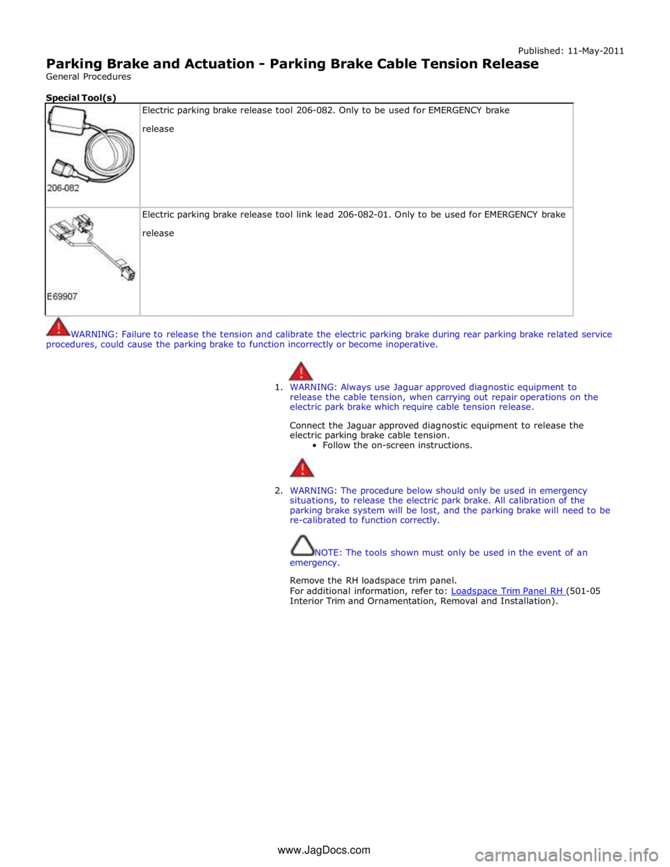
Special Tool(s)
Electric parking brake release tool 206-082. Only to be used for EMERGENCY brake
release
Electric parking brake release tool link lead 206-082-01. Only to be used for EMERGENCY brake
release
WARNING: Failure to release the tension and calibrate the electric parking brake during rear parking brake related service
procedures, could cause the parking brake to function incorrectly or become inoperative.
1. WARNING: Always use Jaguar approved diagnostic equipment to
release the cable tension, when carrying out repair operations on the
electric park brake which require cable tension release.
Connect the Jaguar approved diagnostic equipment to release the
electric parking brake cable tension.
Follow the on-screen instructions.
2. WARNING: The procedure below should only be used in emergency
situations, to release the electric park brake. All calibration of the
parking brake system will be lost, and the parking brake will need to be
re-calibrated to function correctly.
NOTE: The tools shown must only be used in the event of an
emergency.
Remove the RH loadspace trim panel.
For additional information, refer to: Loadspace Trim Panel RH (501-05 Interior Trim and Ornamentation, Removal and Installation). www.JagDocs.com
Page 657 of 3039
7. Connect the electrical connectors in the sequence shown.
8. Install the RH loadspace trim panel.
For additional information, refer to: Loadspace Trim Panel RH (501-05 Interior Trim and Ornamentation, Removal and Installation).
9. WARNING: Calibrate the electric park brake using Jaguar approved
diagnostic equipment. If Jaguar approved diagnostic equipment is not
available disconnect the battery for approximatly 30 seconds , the
vehicle will then prompt the driver to carry out the calibration procedure
as per the vehicle hand book on re-connection.
Calibrate the electric park brake.
Page 662 of 3039
Parking Brake and Actuation - Parking Brake Module
Removal and Installation
Removal
NOTE: Removal steps in this procedure may contain installation details. Published: 11-May-2011
1. Refer to: Battery Disconnect and Connect (414-01 Battery, Mounting and Cables, General Procedures).
2. Refer to: Loadspace Trim Panel RH (501-05 Interior Trim and Ornamentation, Removal and Installation).
Installation
3. Torque: 4 Nm
1. To install, reverse the removal position
2. Configure the electronic parking brake (EPB) using the diagnostic tool.