2010 JAGUAR XFR Electrical relay
[x] Cancel search: Electrical relayPage 225 of 3039

DTC Description Possible Causes Action B1261-13
Fuel Flap/Door Release
Switch - Circuit open
Fuel filler flap digital
input signal circuit -
open circuit
Refer to the electrical circuit diagrams and check
fuel filler flap digital input signal circuit for open
circuit B1A79-11
Rear Fog Lamp - Circuit
short to ground
Rear fog lamp control
circuit - short to ground
Carry out any pinpoint test associated with this DTC
using the manufacturer approved diagnostic system.
Refer to the electrical circuit diagrams and check
rear fog lamp control circuit for short to ground B1A79-12
Rear Fog Lamp - Circuit
short to battery
Rear fog lamp control
circuit - short to power
Refer to the electrical circuit diagrams and check
rear fog lamp control circuit for short to power B1A79-13
Rear Fog Lamp - Circuit
open
Rear fog lamp control
circuit - open circuit
Refer to the electrical circuit diagrams and check
rear fog lamp control circuit for open circuit B1C55-12
Horn Relay - Circuit
short to battery
Horn control circuit -
short to power
Refer to the electrical circuit diagrams and check
horn control circuit for short to power B1C55-14
Horn Relay - Circuit
short to ground or open
Horn control circuit -
short to ground, open
circuit
Refer to the electrical circuit diagrams and check
horn control circuit for short to ground, open circuit B1C83-12
Rear Defog Relay -
Circuit short to battery
High Side output not
driven - diagnosis
feedback indicates
output is short to power
Refer to the electrical circuit diagrams and check
heated rear window power supply circuit for short to
power B1C83-14
Rear Defog Relay -
Circuit short to ground
or open
High Side output not
driven - diagnosis
feedback indicates
output is short to
ground, open circuit
Refer to the electrical circuit diagrams and check
heated rear window power supply circuit for short to
ground, open circuit B1C83-93
Rear Defog Relay - No
operation
High Side output not
driven - diagnosis
feedback indicates
output is at open load
or short to power
Carry out any pinpoint test associated with this DTC
using the manufacturer approved diagnostic system.
Refer to the electrical circuit diagrams and check
heated rear window power supply circuit for open
load and short to power B1C91-12
Fuel Flap/Door Lock
Relay Coil Circuit -
Circuit short to battery
Fuel filler flap locking
motor control circuit -
short to power
Refer to the electrical circuit diagrams and check
fuel filler flap locking motor control circuit for short
to power B1C91-14
Fuel Flap/Door Lock
Relay Coil Circuit -
Circuit short to ground
or open
Fuel filler flap locking
motor control circuit -
short to ground, open
circuit
Refer to the electrical circuit diagrams and check
fuel filler flap locking motor control circuit for short
to ground, open circuit B1D35-12
Hazard Switch - Circuit
short to battery
Hazard warning lamp
switch digital input
circuit - short to power
Refer to the electrical circuit diagrams and check
hazard warning lamp switch digital input circuit for
short to power B1D35-23
Hazard Switch - Signal
stuck low
Hazard warning lamp
switch digital input
circuit - signal stuck low
Carry out any pinpoint test associated with this DTC
using the manufacturer approved diagnostic system.
Refer to the electrical circuit diagrams and check
hazard warning lamp switch digital input circuit for
short to ground U0019-88
Low Speed CAN
Communication Bus -
Bus off
Bus off
Carry out any pinpoint test associated with this DTC
using the manufacturer approved diagnostic system U0140-00
Lost Communication
With Body Control
Module - No sub type
information
No sub type information
Carry out any pinpoint test associated with this DTC
using the manufacturer approved diagnostic system
Page 484 of 3039

each damper to the appropriate level to maintain a flat and level body.
Roll Rate Control – Uses CAN inputs. Predicts vehicle roll rate due to driver steering inputs 100 times a second and increases damping to reduce roll rate.
Pitch Rate Control – Uses CAN inputs. Predicts vehicle pitch rate due to driver throttle and braking inputs 100 times a second and increases damping to reduce pitch rate.
Bump Rebound Control – Uses suspension height sensor and CAN inputs. Monitors the position of the wheel 500 times a second and increases the damping rate as the damper approaches the end of its travel.
Wheel Hop Control – Uses suspension height sensor and CAN inputs. Monitors the position of the wheel 500 times a second and detects when the wheel is at its natural frequency and increases the dampingto reduce vertical wheel
motion.
Under normal road conditions when the vehicle is stationary with the engine running, the dampers are set to the firm condition
to reduce power consumption.
The adaptive damping module receives its power supply via a relay and fuse in the CJB. The relay remains energized for a period of time after the ignition is off. This allows the adaptive damping module to record and store any DTC (diagnostic
trouble code) relating to adaptive dynamics system faults.
DAMPERS Component Description
Item Description A Front spring and damper assembly B Rear spring and damper assembly The 'Adaptive Dynamics' dampers are monotube, nitrogen gas and oil filled units, manufactured by Bilstein. The dampers are
continuously variable, which allows the damping force to be electrically adjusted when the vehicle is being driven. The variable
dampers provide the optimum compromise between vehicle control and ride comfort.
The dampers have an electrical connector on the end of the piston rod, in the center of the top mount (the dampers look
identical to those on the Computer Active Technology Suspension (CATS) system of 4.2L supercharged vehicles, but have a
different part number).
In each damper, the continuous damping adjustment is achieved by a solenoid operated variable orifice, which opens up an
alternative path for oil flow within the damper. When de-energized the bypass is closed and all the oil flows through the main
(firm) piston. When energized, the solenoid moves an armature and control blade, which work against a spring. The control
blade incorporates an orifice which slides inside a sintered housing to open up the bypass as required. In compression, oil
flows from the lower portion of the damper through a hollow piston rod, a separate soft (comfort) valve, the slider housing and
orifice and into the upper portion of the damper, thereby bypassing the main (firm) valve. In rebound the oil flows in the www.JagDocs.com
Page 538 of 3039

Rear Drive Axle/Differential - Rear Drive Axle and Differential
Diagnosis and Testing
Principle of Operation Published: 12-May-2014
For a detailed description of the Rear Drive Axle and Differential, refer to the relevant Description and Operation section in the
workshop manual. REFER to: Rear Drive Axle and Differential (205-02 Rear Drive Axle/Differential, Description and Operation).
Inspection and Verification
CAUTION: Diagnosis by substitution from a donor vehicle is NOT acceptable. Substitution of control modules does not
guarantee confirmation of a fault, and may also cause additional faults in the vehicle being tested and/or the donor vehicle.
1. Verify the customer concern.
2. Visually inspect for obvious signs of damage and system integrity.
Mechanical Electrical
Fixings that secure Rear Differential Control Module (Heat path
for Module Heatsink)
Fuses/Relays
Damaged, Loose or Corroded Connector(s)
Damage to Wiring Loom/Incorrect Location,
Stretched or Taught
3. If an obvious cause for an observed or reported concern is found, correct the cause (if possible) before proceeding to
the next step.
4. If the cause is not visually evident, check the system for any logged Diagnostic Trouble Codes (DTCs) and refer to the
DTC index.
DTC Index
For a list of diagnostic trouble codes that could be logged on this vehicle, please refer to Section 100-00. REFER to: Diagnostic Trouble Code (DTC) Index - DTC: Rear Differential Control Module (RDCM) (100-00 General Information, Description and Operation).
Page 813 of 3039
Component Tests
Engine Oil Leaks
NOTE: Before installing new gaskets or oil seals, make sure that the fault is clearly established.
If the oil leak cannot be identified clearly by a visual inspection, carry out an Ultraviolet test:
Fluorescent Oil Additive Method
1. Clean the engine with a suitable cleaning fluid (brake cleaner).
2. Drain the engine oil and refill with recommended oil, premixed with Diesel Engine Oil Dye or equivalent. Use a minimum
14.8 ml (0.5 ounce) to a maximum 29.6 ml (1 ounce) of fluorescent additive to all engines. If oil is not premixed,
fluorescent additive must first be added to the crankcase.
3. Run engine for 15 minutes. Stop the engine and inspect all seal and gasket areas for leaks using a 12 Volt Master UV
Diagnostic Inspection Kit or equivalent. A clear bright yellow or orange area will identify leak. For extremely small
leaks, several hours may be required for the leak to appear.
4. As necessary, pressurize the main oil gallery system to locate leaks due to incorrectly sealed, loose or cocked plugs. If
the flywheel bolts leak oil, look for sealer on the threads.
5. Repair all leaks as necessary.
Compression Test General Remarks
NOTES:
Removing fuses and disconnecting electrical components may cause the Engine Control Module (ECM) to log Diagnostic
Trouble Codes (DTCs). After the measurements have been carried out, DTCs should be cleared from memory by connecting to
the Manufacturer Approved Diagnostic System.
Only check the compression pressure with the valves set to the prescribed clearance (if this can be adjusted).
The compression pressure should be checked with the engine at normal operating temperature.
Check the Compression Pressure
WARNING: Move gear selector lever to 'P' position. Failure to follow this instruction may result in personal injury.
1. Remove the fuel pump relay.
2. Start the engine - the engine will start, run for a few seconds then stall.
3. Remove the spark plugs.
4. Install the compression tester.
5. Install an auxiliary starter switch in the starting circuit. With the ignition switch OFF, using the auxiliary starter switch,
crank the engine a minimum of five compression strokes and record the highest reading. Note the approximate number
of compression strokes required to obtain the highest reading.
6. Repeat the test on each cylinder, cranking the engine approximately the same number of compression strokes.
7. Install the removed components in reverse order, observing the specified tightening torques.
8. Clear all DTCs from the ECM.
Interpretation of the Results
NOTE: Due to the possibility of loose carbon that has become trapped between the valve face and seat effecting the
pressure readings, when carrying out a compression test and cylinders are found to have low pressures, install the spark plugs,
road test the vehicle and re-test the suspect cylinders. If the correct pressures are restored, no further action is required.
The indicated compression pressures are considered within specification if the lowest reading cylinder is within 75% of the
highest reading.
If the cylinder pressures are found to be low, carry out a leakdown test to determine the location of the fault (if any leakback
can be heard through the engine breather system suspect the piston rings, if any leakback can be heard through the inlet
system suspect the inlet valve or seat, if any leakback can be heard through the exhaust manifold suspect the exhaust valve
or seat. If the measurements for two cylinders next to each other are both too low then it is very likely that the cylinder head
gasket between them is burnt through. This can also be recognized by traces of engine oil in the coolant and/or coolant in the
Page 1123 of 3039
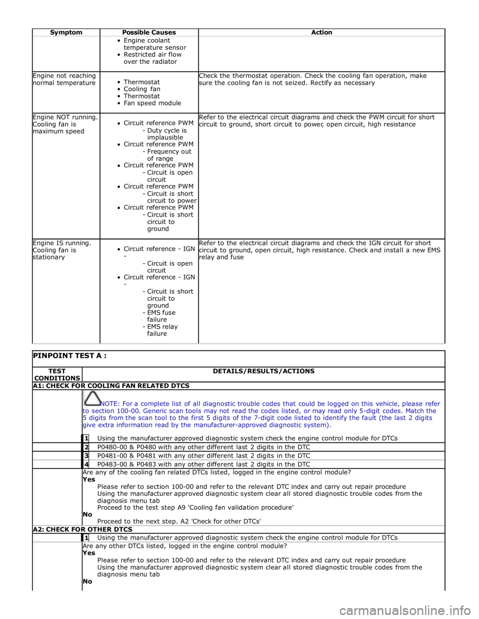
Symptom Possible Causes Action Engine coolant
temperature sensor
Restricted air flow
over the radiator Engine not reaching
normal temperature
Thermostat
Cooling fan
Thermostat
Fan speed module Check the thermostat operation. Check the cooling fan operation, make
sure the cooling fan is not seized. Rectify as necessary Engine NOT running.
Cooling fan is
maximum speed
Circuit reference PWM
- Duty cycle is
implausible
Circuit reference PWM
- Frequency out
of range
Circuit reference PWM
- Circuit is open
circuit
Circuit reference PWM
- Circuit is short
circuit to power
Circuit reference PWM
- Circuit is short
circuit to
ground Refer to the electrical circuit diagrams and check the PWM circuit for short
circuit to ground, short circuit to power, open circuit, high resistance Engine IS running.
Cooling fan is
stationary
Circuit reference - IGN
-
- Circuit is open
circuit
Circuit reference - IGN
-
- Circuit is short
circuit to
ground
- EMS fuse
failure
- EMS relay
failure Refer to the electrical circuit diagrams and check the IGN circuit for short
circuit to ground, open circuit, high resistance. Check and install a new EMS
relay and fuse
PINPOINT TEST A : TEST
CONDITIONS DETAILS/RESULTS/ACTIONS A1: CHECK FOR COOLING FAN RELATED DTCS
NOTE: For a complete list of all diagnostic trouble codes that could be logged on this vehicle, please refer
to section 100-00. Generic scan tools may not read the codes listed, or may read only 5-digit codes. Match the
5 digits from the scan tool to the first 5 digits of the 7-digit code listed to identify the fault (the last 2 digits
give extra information read by the manufacturer-approved diagnostic system). 1 Using the manufacturer approved diagnostic system check the engine control module for DTCs 2 P0480-00 & P0480 with any other different last 2 digits in the DTC 3 P0481-00 & P0481 with any other different last 2 digits in the DTC 4 P0483-00 & P0483 with any other different last 2 digits in the DTC Are any of the cooling fan related DTCs listed, logged in the engine control module?
Yes
Please refer to section 100-00 and refer to the relevant DTC index and carry out repair procedure
Using the manufacturer approved diagnostic system clear all stored diagnostic trouble codes from the
diagnosis menu tab
Proceed to the test step A9 'Cooling fan validation procedure'
No
Proceed to the next step. A2 'Check for other DTCs' A2: CHECK FOR OTHER DTCS 1 Using the manufacturer approved diagnostic system check the engine control module for DTCs Are any other DTCs listed, logged in the engine control module?
Yes
Please refer to section 100-00 and refer to the relevant DTC index and carry out repair procedure
Using the manufacturer approved diagnostic system clear all stored diagnostic trouble codes from the
diagnosis menu tab
No
Page 1170 of 3039
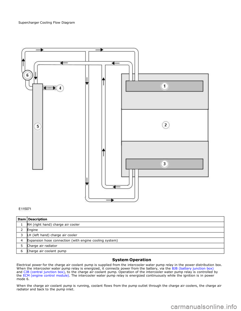
1 RH (right hand) charge air cooler 2 Engine 3 LH (left hand) charge air cooler 4 Expansion hose connection (with engine cooling system) 5 Charge air radiator 6 Charge air coolant pump
System Operation
Electrical power for the charge air coolant pump is supplied from the intercooler water pump relay in the power distribution box.
When the intercooler water pump relay is energized, it connects power from the battery, via the BJB (battery junction box)
and CJB (central junction box), to the charge air coolant pump. Operation of the intercooler water pump relay is controlled by
the ECM (engine control module). The intercooler water pump relay is energized continuously while the ignition is in power
mode 6.
When the charge air coolant pump is running, coolant flows from the pump outlet through the charge air coolers, the charge air
radiator and back to the pump inlet. Supercharger Cooling Flow Diagram
Page 1263 of 3039
Published: 11-May-2011
Starting System - V8 5.0L Petrol/V8 S/C 5.0L Petrol - Starting System
Diagnosis and Testing
Principles of Operation
For a detailed description of the starting system and operation, refer to the relevant Description and Operation section of the
workshop manual. REFER to: (303-06C Starting System - V8 5.0L Petrol/V8 S/C 5.0L Petrol)
Starting System (Description and Operation), Starting System (Description and Operation), Starting System (Description and Operation).
Inspection and Verification
CAUTION: Diagnosis by substitution from a donor vehicle is NOT acceptable. Substitution of control modules does not
guarantee confirmation of a fault and may also cause additional faults in the vehicle being checked and/or the donor vehicle.
NOTE: Check and rectify basic faults before beginning diagnostic routines involving pinpoint tests.
1. Verify the customer concern.
2. Visually inspect for obvious signs of mechanical and electrical damage.
Visual Inspection
Mechanical Electrical
Gear selector lever cable adjustment (vehicles with automatic
transmission)
Starter motor
Engine (turns freely)
Battery
Fuses
Starter relay
Wiring harness(es)
Damaged, loose or corroded
connectors
Ignition switch
Generator
Transmission Control Module (TCM)
Engine Control Module (ECM)
3. If an obvious cause for an observed or reported concern is found, correct the cause (if possible) before proceeding to
the next step.
4. If the cause is not visually evident, verify the symptom and refer to the Symptom Chart, alternatively check for
Diagnostic Trouble Codes (DTCs) and refer to the DTC Index.
Symptom Chart
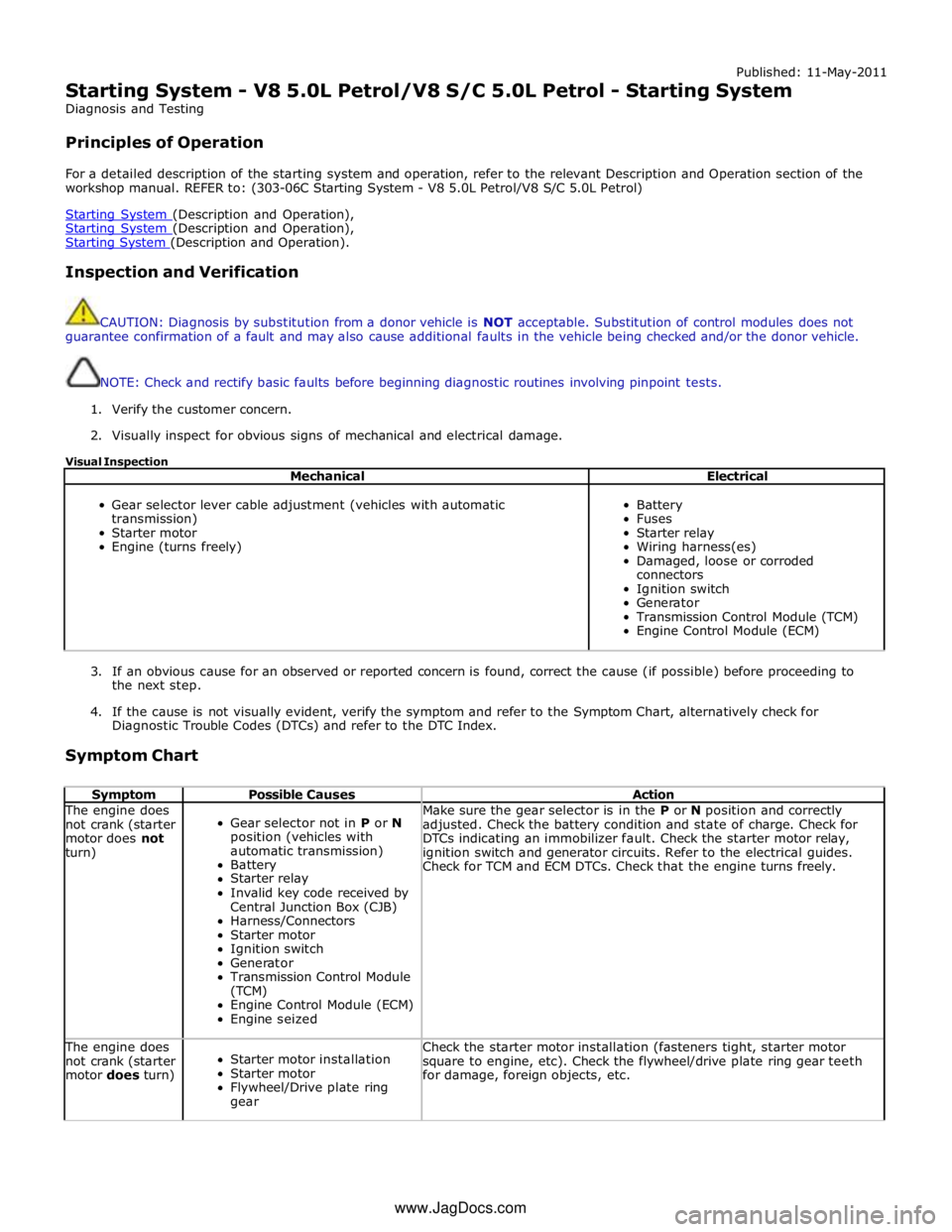
Symptom Possible Causes Action The engine does
not crank (starter
motor does not
turn)
Gear selector not in P or N
position (vehicles with
automatic transmission)
Battery
Starter relay
Invalid key code received by
Central Junction Box (CJB)
Harness/Connectors
Starter motor
Ignition switch
Generator
Transmission Control Module
(TCM)
Engine Control Module (ECM)
Engine seized Make sure the gear selector is in the P or N position and correctly
adjusted. Check the battery condition and state of charge. Check for
DTCs indicating an immobilizer fault. Check the starter motor relay,
ignition switch and generator circuits. Refer to the electrical guides.
Check for TCM and ECM DTCs. Check that the engine turns freely. The engine does
not crank (starter
motor does turn)
Starter motor installation
Starter motor
Flywheel/Drive plate ring
gear Check the starter motor installation (fasteners tight, starter motor
square to engine, etc). Check the flywheel/drive plate ring gear teeth
for damage, foreign objects, etc. www.JagDocs.com
Page 1274 of 3039
GENERAL System Operation
The ignition coils are supplied with electrical power from the battery via a 250 A megafuse in the BJB (battery junction box)
and the ignition relay in the EJB (engine junction box). The control signal for the ignition relay is supplied by the CJB (central
junction box).
The ECM (engine control module) sends a separate signal to each ignition coil to trigger the power stage switching. The ECM calculates the dwell time from the battery voltage and engine speed, to ensure a constant energy level is produced in the
secondary coil each time the power stage is switched. This ensures sufficient spark energy is available without excessive
primary current flow, which avoids overheating and damage to the ignition coils.
The ECM calculates the ignition timing for individual cylinders from: Engine speed
Camshaft position
Engine load
Engine temperature
The knock control function
The shift control function
The idle speed control function.
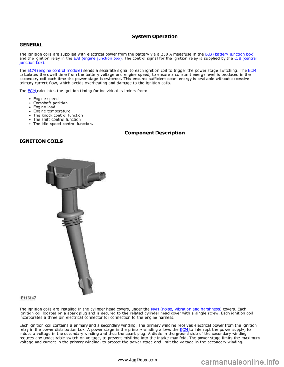
IGNITION COILS Component Description
The ignition coils are installed in the cylinder head covers, under the NVH (noise, vibration and harshness) covers. Each
ignition coil locates on a spark plug and is secured to the related cylinder head cover with a single screw. Each ignition coil
incorporates a three pin electrical connector for connection to the engine harness.
Each ignition coil contains a primary and a secondary winding. The primary winding receives electrical power from the ignition
relay in the power distribution box. A power stage in the primary winding allows the ECM to interrupt the power supply, to induce a voltage in the secondary winding and thus the spark plug. A diode in the ground side of the secondary winding
reduces any undesirable switch-on voltage, to prevent misfiring into the intake manifold. The power stage limits the maximum
voltage and current in the primary winding, to protect the power stage and limit the voltage in the secondary winding. www.JagDocs.com