Page 2593 of 3039

Safety Belt System - Safety Belt System - Overview
Description and Operation
Authoring Template
OVERVIEW Published: 11-May-2011
A three point safety belt is fitted to all seating positions. Each safety belt retractor incorporates an emergency locking feature.
The emergency locking retractor incorporates 2 mechanical inertia devices. One inertia device activates if the safety belt is
subjected to a sharp pull. The second inertia device activates if the vehicle is subject to a sudden deceleration or is on a
severe incline.
North American Specification (NAS) safety belt retractors also include an automatic locking feature. The Automatic Locking
Retractor (ALR) is fitted to all passenger seating positions and allows the safety belt to be tensioned to aid the safe fitment
of child or booster seats. For additional information, refer to the Owners Handbook.
NAS vehicles are also fitted with a belt tension sensor on the front passenger seat. The belt tension sensor is incorporated
into the seat belt lower anchorage and is attached to the seat frame by an M10 Torx head bolt. The belt tension sensor forms
part of the SRS (supplemental restraint system) occupancy detection and classification feature.
The center rear safety belt features a mini-buckle lower anchorage. The mini-buckle is disengaged by inserting a suitable tool
into the small aperture on the front face of the housing.
To aid the fitment of child seats, 3 tethers are located on the rear parcel shelf. Each tether is attached to the parcel shelf with
an M10 Torx head bolt.
A safety belt warning indicator is located in the instrument cluster to remind front seat passengers to fasten their safety belts.
The warning indicator will illuminate if the safety belt of an occupied front seat is not fastened.
Refer to: Instrument Cluster (413-01, Description and Operation).
Page 2610 of 3039
1 Occupant classification system pressure pad (NAS only) 2 Safety belt tension sensor (NAS only) 3 Occupant detection system pad (all, except NAS) 4 Occupant classification system control module (NAS only) 5 RH side impact sensor (pressure sensor) 6 RH rear impact sensor 7 LH rear impact sensor 8 Passenger airbag deactivation LED (light emitting diode) 9 Driver's seat position sensor 10 LH side impact sensor (pressure sensor) 11 Instrument cluster 12 LH front impact sensor 13 RH front impact sensor
Page 2611 of 3039

Published: 30-May-2012
Supplemental Restraint System - Air Bag and Safety Belt Pretensioner
Supplemental Restraint System (SRS) - Overview
Description and Operation
OVERVIEW
WARNING: All pyrotechnic devices are dangerous. Before performing any procedures on any pyrotechnic device, read all
information contained within the Standard Workshop Practices section of this manual.
Refer to: Standard Workshop Practices (100-00 General Information, Description and Operation).
The SRS (supplemental restraint system) provides additional protection for the vehicle occupants in certain impact conditions.
The system is controlled by the RCM (restraints control module), which is mounted beneath the floor console. The system
includes twin stage drivers and front passenger airbags.
The RCM receives inputs from various sensors around the vehicle and determines which, if any, airbags should be deployed.
The SRS features an occupant detection system. The occupant detection system comprises a mat fitted inside the front passenger seat. By monitoring the condition of the mat, the RCM can determine if the front passenger seat is occupied. It uses this information to determine which airbags to deploy in the event of an impact. This information is also used to illuminate the
safety belt instrument cluster warning lamp if the front passenger seat is occupied and the safety belt is not engaged.
North American Specification (NAS) vehicles also feature an occupant classification system. The occupant classification system
comprises a control module, pressure pad and safety belt tension sensor. The system can determine the size and weight of the
front seat passenger. This information is transmitted to the RCM over the high speed CAN (controller area network) bus. The RCM uses this information to help determine which airbags to deploy in the event of an impact.
Page 2613 of 3039
6 Occupant classification system pressure pad (NAS only) 7 Passenger airbag deactivation LED (light emitting diode) 8 Instrument cluster 9 Occupant detection system pad (all, except NAS) 10 Driver's seat position sensor 11 Front passenger seat safety belt pretensioner 12 Driver's seat safety belt pretensioner 13 LH (left-hand) front impact sensor 14 RH (right-hand) front impact sensor 15 RH rear impact sensor 16 RH side impact sensor 17 LH rear impact sensor 18 LH side impact sensor 19 RCM (restraints control module)
Page 2615 of 3039

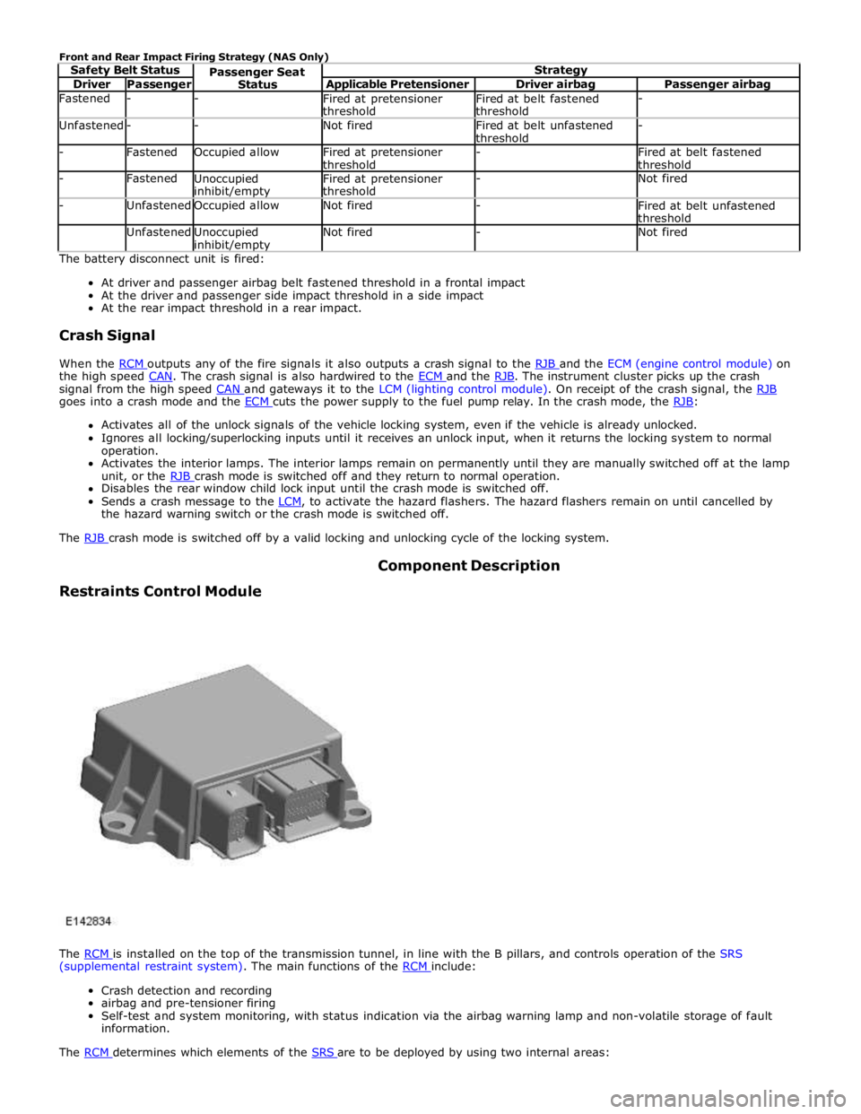
Driver Passenger Applicable Pretensioner Driver airbag Passenger airbag Fastened - -
Fired at pretensioner
threshold Fired at belt fastened
threshold - Unfastened - - Not fired
Fired at belt unfastened
threshold - - Fastened Occupied allow
Fired at pretensioner
threshold -
Fired at belt fastened
threshold - Fastened
Unoccupied inhibit/empty Fired at pretensioner
threshold - Not fired - Unfastened Occupied allow Not fired -
Fired at belt unfastened
threshold Unfastened
Unoccupied inhibit/empty Not fired - Not fired The battery disconnect unit is fired:
At driver and passenger airbag belt fastened threshold in a frontal impact
At the driver and passenger side impact threshold in a side impact
At the rear impact threshold in a rear impact.
Crash Signal
When the RCM outputs any of the fire signals it also outputs a crash signal to the RJB and the ECM (engine control module) on the high speed CAN. The crash signal is also hardwired to the ECM and the RJB. The instrument cluster picks up the crash signal from the high speed CAN and gateways it to the LCM (lighting control module). On receipt of the crash signal, the RJB goes into a crash mode and the ECM cuts the power supply to the fuel pump relay. In the crash mode, the RJB: Activates all of the unlock signals of the vehicle locking system, even if the vehicle is already unlocked.
Ignores all locking/superlocking inputs until it receives an unlock input, when it returns the locking system to normal
operation.
Activates the interior lamps. The interior lamps remain on permanently until they are manually switched off at the lamp
unit, or the RJB crash mode is switched off and they return to normal operation. Disables the rear window child lock input until the crash mode is switched off.
Sends a crash message to the LCM, to activate the hazard flashers. The hazard flashers remain on until cancelled by the hazard warning switch or the crash mode is switched off.
The RJB crash mode is switched off by a valid locking and unlocking cycle of the locking system.
Restraints Control Module Component Description
The RCM is installed on the top of the transmission tunnel, in line with the B pillars, and controls operation of the SRS (supplemental restraint system). The main functions of the RCM include:
Crash detection and recording
airbag and pre-tensioner firing
Self-test and system monitoring, with status indication via the airbag warning lamp and non-volatile storage of fault
information.
The RCM determines which elements of the SRS are to be deployed by using two internal areas:
Page 2621 of 3039

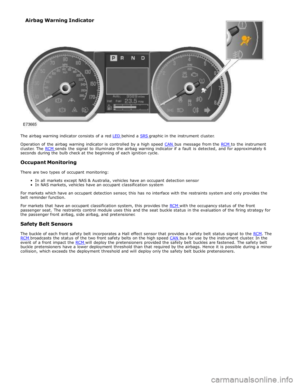
Operation of the airbag warning indicator is controlled by a high speed CAN bus message from the RCM to the instrument cluster. The RCM sends the signal to illuminate the airbag warning indicator if a fault is detected, and for approximately 6 seconds during the bulb check at the beginning of each ignition cycle.
Occupant Monitoring
There are two types of occupant monitoring:
In all markets except NAS & Australia, vehicles have an occupant detection sensor
In NAS markets, vehicles have an occupant classification system
For markets which have an occupant detection sensor, this has no interface with the restraints system and only provides the
belt reminder function.
For markets that have an occupant classification system, this provides the RCM with the occupancy status of the front passenger seat. The restraints control module uses this and the seat buckle status in the evaluation of the firing strategy for
the passenger front airbag, side airbag, and pretensioner.
Safety Belt Sensors
The buckle of each front safety belt incorporates a Hall effect sensor that provides a safety belt status signal to the RCM. The RCM broadcasts the status of the two front safety belts on the high speed CAN bus for use by the instrument cluster. In the event of a front impact the RCM will deploy the pretensioners provided the safety belt buckles are fastened. The safety belt buckle pretensioners have a lower deployment threshold than that required by the airbags. Hence it is possible during a minor
collision, which exceeds the deployment threshold and will deploy only the safety belt buckle pretensioners. Airbag Warning Indicator
Page 2656 of 3039
12.
13. CAUTION: Take extra care not to damage the
instrument cluster face.
Special Tool(s): 211-326
Page 2683 of 3039
Published: 11-May-2011
Pedestrian Protection System - Pedestrian Protection System - System
Operation and Component Description
Description and Operation
Control Diagram
NOTE: A = Hardwired; D = High speed CAN (controller area network) bus; N = Medium speed CAN bus
Item Description 1 Battery 2 CJB (central junction box) 3 Instrument cluster 4 LH (left-hand) hood actuator 5 RH (right-hand) hood actuator 6 Pedestrian protection system control module