2010 JAGUAR XFR instrument cluster
[x] Cancel search: instrument clusterPage 2333 of 3039

DTC Description Possible Cause Action B1C0024
Seat Recline Up
Switch
Signal stuck high Check for a stuck switch. Refer to the electrical circuit
diagrams and check driver seat switch pack to seat
module LIN circuit for short, open circuit and seat
recline up circuit for short to ground B1C0124
Seat Recline Down
Switch
Signal stuck high Check for a stuck switch. Refer to the electrical circuit
diagrams and check driver seat switch pack to seat
module LIN circuit for short, open circuit and check seat
recline down circuit for short to ground B1C0224 Memory Store Switch
Signal stuck high Check for a stuck switch. Refer to the electrical circuit
diagrams and check driver seat switch pack to seat
module LIN circuit for short, open circuit B1C0324 Memory #1 Switch
Signal stuck high Check for a stuck switch. Refer to the electrical circuit
diagrams and check driver seat switch pack to seat
module LIN circuit for short, open circuit B1C0424 Memory #2 Switch
Signal stuck high Check for a stuck switch. Refer to the electrical circuit
diagrams and check driver seat switch pack to seat
module LIN circuit for short, open circuit B1C0524 Memory #3 Switch
Signal stuck high Check for a stuck switch. Refer to the electrical circuit
diagrams and check driver seat switch pack to seat
module LIN circuit for short, open circuit U001088
Medium speed Can
communication Bus
Bus off Carry out any pinpoint tests associated with this DTC
using the manufacturer approved diagnostic system.
Refer to the electrical circuit diagrams and check CAN
network to climate controlled seat module for short, open circuit U014000
Lost communication
with CJB
Lost communication with CJB Carry out any pinpoint tests associated with this DTC
using the manufacturer approved diagnostic system.
Check CJB for related DTCs and refer to the relevant
DTC Index U014200
Lost communication
with RJB
Lost communication with RJB Carry out any pinpoint tests associated with this DTC
using the manufacturer approved diagnostic system.
Check RJB for related DTCs and refer to the relevant
DTC Index U015500
Lost
communications
with instrument
cluster
Lost communications with
instrument cluster Carry out any pinpoint tests associated with this DTC
using the manufacturer approved diagnostic system.
Refer to the electrical circuit diagrams and check CAN
network to climate controlled seat module and
instrument cluster for short, open circuit U019900
Lost communication
with Driver Door
Module (DDM)
Lost communication with DDM Carry out any pinpoint tests associated with this DTC
using the manufacturer approved diagnostic system U030000
Internal control
module software
incompatibility
Invalid configuration message is
received Re-configure the RJB using the manufacturer approved
diagnostic system. Clear the DTC and retest. If the DTC
is still logged suspect the DSM/PSM, refer to the new
module installation note at the top of the DTC Index U1A1449
CAN Initialisation
failure
Internal electronic failure Install a new DSM, refer to the new module installation
note at the top of the DTC Index U1A4C68
Build/end of line
mode active
Manufacturing mode has not
been removed Place DSM in to customer mode using manufacturer
approved diagnostic system U300049 Control module
Internal electronic failure Install a new DSM, refer to the new module installation
note at the top of the DTC Index U300055
Stored vehicle
configuration data
does not match
Incorrect car configuration data
received Re-configure the RJB using the manufacturer approved
diagnostic system. Clear DTC and re-test. If the DTC
remains suspect the DSM, refer to the new module
installation note at the top of the DTC Index U300087 Control Module
Missing message Re-configure the RJB using the manufacturer approved
diagnostic system. Check DSM for DTCs and refer to the
DTC Index. Check CAN network integrity using the
manufacturer approved diagnostic system U300146
Control module
improper shutdown
Calibration/parameter memory
failure Check for DTCs that could indicate power failure to the
module and refer to the DTC Index U300281
Vehicle
Identification
Number (VIN)
Vehicle/component mis-match.
Corrupt VIN data being
transmitted, module previously
installed to other vehicle Install original module, check for DTCs and refer to
relevant DTC Index U300316 Battery Voltage
Circuit voltage below threshold Carry out any pinpoint tests associated with this DTC
using the manufacturer approved diagnostic system
Page 2352 of 3039
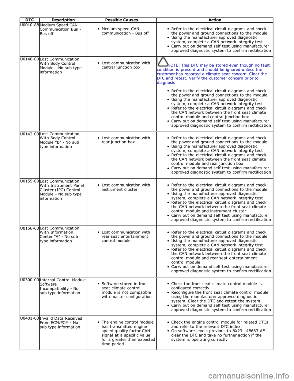
DTC Description Possible Causes Action U0010-88
Medium Speed CAN
Communication Bus -
Bus off
Medium speed CAN
communication - Bus off
Refer to the electrical circuit diagrams and check
the power and ground connections to the module
Using the manufacturer approved diagnostic
system, complete a CAN network integrity test
Carry out on demand self test using manufacturer
approved diagnostic system to confirm rectification U0140-00
Lost Communication
With Body Control
Module - No sub type
information
Lost communication with
central junction box
NOTE: This DTC may be stored even though no fault
condition is present and should be ignored unless the
customer has reported a climate seat concern. Clear the
DTC and retest. Verify the customer concern prior to
diagnosis
Refer to the electrical circuit diagrams and check
the power and ground connections to the module
Using the manufacturer approved diagnostic
system, complete a CAN network integrity test
Refer to the electrical circuit diagrams and check
the CAN network between the front seat climate
control module and central junction box
Carry out on demand self test using manufacturer
approved diagnostic system to confirm rectification U0142-00 Lost Communication
Lost communication with
Refer to the electrical circuit diagrams and check With Body Control Module "B" - No sub rear junction box the power and ground connections to the module type information Using the manufacturer approved diagnostic system, complete a CAN network integrity test Refer to the electrical circuit diagrams and check the CAN network between the front seat climate control module and rear junction box Carry out on demand self test using manufacturer approved diagnostic system to confirm rectification U0155-00
Lost Communication
With Instrument Panel
Cluster (IPC) Control
Module - No sub type
information
Lost communication with
instrument cluster
Refer to the electrical circuit diagrams and check
the power and ground connections to the module
Using the manufacturer approved diagnostic
system, complete a CAN network integrity test
Refer to the electrical circuit diagrams and check
the CAN network between the front seat climate
control module and instrument cluster
Carry out on demand self test using manufacturer
approved diagnostic system to confirm rectification U0156-00 Lost Communication
Lost communication with
Refer to the electrical circuit diagrams and check With Information Center "A" - No sub rear seat entertainment the power and ground connections to the module type information control module Using the manufacturer approved diagnostic system, complete a CAN network integrity test Refer to the electrical circuit diagrams and check the CAN network between the front seat climate control module and rear seat entertainment control module Carry out on demand self test using manufacturer approved diagnostic system to confirm rectification U0300-00
Internal Control Module
Software
Incompatibility - No
sub type information
Software stored in front
seat climate control
module is not compatible
with master configuration
Check the front seat climate control module is
configured correctly
Reconfigure the front seat climate control module
using the manufacturer approved diagnostic
system. Clear the DTC and retest the system
Carry out on demand self test using manufacturer
approved diagnostic system to confirm rectification U0401-00
Invalid Data Received
From ECM/PCM - No
sub type information
The engine control module
has transmitted engine
speed quality factor CAN
signal at a specific value
for a greater than expected
time period
Check the engine control module for related DTCs
and refer to the relevant DTC index
On software levels previous to 8X23-14B663-AE
clear the DTC and take no further action if the
system is operating correctly
Page 2492 of 3039
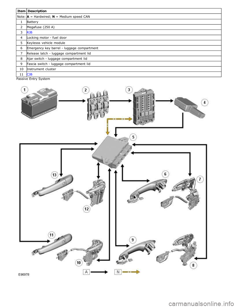
Note: A = Hardwired; N = Medium speed CAN 1 Battery 2 Megafuse (250 A) 3 RJB 4 Locking motor - fuel door 5 Keylesss vehicle module 6 Emergency key barrel - luggage compartment 7 Release latch - luggage compartment lid 8 Ajar switch - luggage compartment lid 9 Fascia switch - luggage compartment lid 10 Instrument cluster 11 CJB Passive Entry System
Page 2496 of 3039
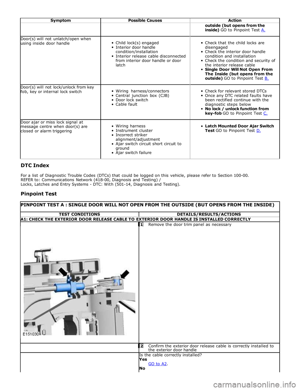
Symptom Possible Causes Action outside (but opens from the
inside) GO to Pinpoint Test A. Door(s) will not unlatch/open when
using inside door handle
Child lock(s) engaged
Interior door handle
condition/installation
Interior release cable disconnected
from interior door handle or door
latch
Check that the child locks are
disengaged
Check the interior door handle
condition and installation
Check the condition and security of
the interior release cable
Single Door Will Not Open From
The Inside (but opens from the
outside) GO to Pinpoint Test B. Door(s) will not lock/unlock from key
fob, key or internal lock switch
Wiring harness/connectors
Central junction box (CJB)
Door lock switch
Cable fault
Check for relevant stored DTCs
Once any DTC related faults have
been rectified continue with the
diagnostic steps below
No lock / unlock function from
key-fob GO to Pinpoint Test C. Door ajar or miss lock signal at
message centre when door(s) are
closed or alarm triggering
Wiring harness
Instrument cluster
Incorrect striker
alignment/adjustment
Ajar switch circuit short circuit to
ground
Ajar switch failure
Latch Mounted Door Ajar Switch
Test GO to Pinpoint Test D. DTC Index
For a list of Diagnostic Trouble Codes (DTCs) that could be logged on this vehicle, please refer to Section 100-00.
REFER to: Communications Network (418-00, Diagnosis and Testing) /
Locks, Latches and Entry Systems - DTC: With (501-14, Diagnosis and Testing).
Pinpoint Test
PINPOINT TEST A : SINGLE DOOR WILL NOT OPEN FROM THE OUTSIDE (BUT OPENS FROM THE INSIDE) TEST CONDITIONS DETAILS/RESULTS/ACTIONS A1: CHECK THE EXTERIOR DOOR RELEASE CABLE TO EXTERIOR DOOR HANDLE IS INSTALLED CORRECTLY
1 Remove the door trim panel as necessary 2 Confirm the exterior door release cable is correctly installed to the exterior door handle Is the cable correctly installed?
Yes
GO to A2. No
Page 2535 of 3039
Wipers and Washers - Wipers and Washers - Overview
Description and Operation
OVERVIEW Published: 11-May-2011
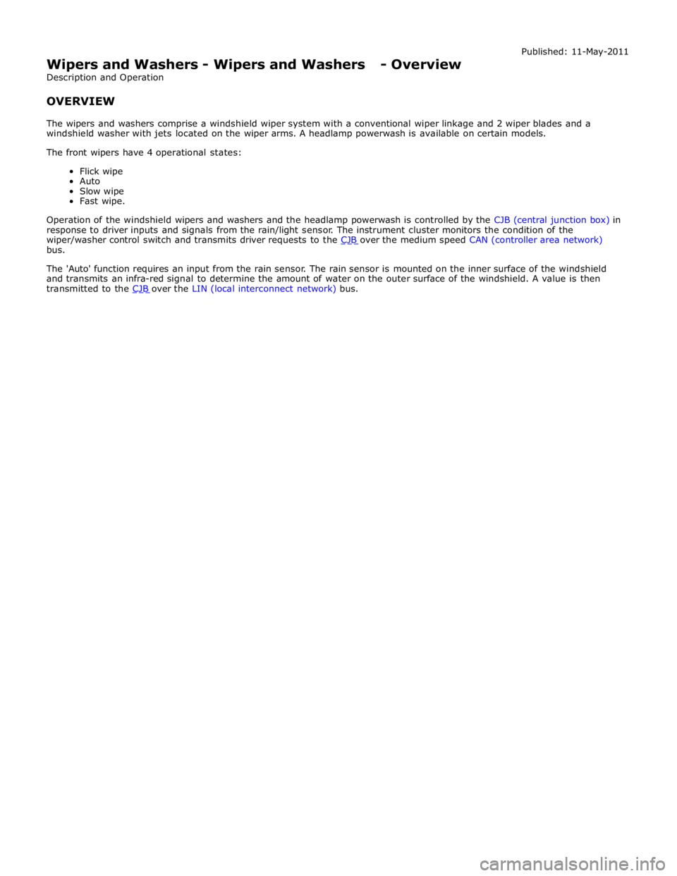
The wipers and washers comprise a windshield wiper system with a conventional wiper linkage and 2 wiper blades and a
windshield washer with jets located on the wiper arms. A headlamp powerwash is available on certain models.
The front wipers have 4 operational states:
Flick wipe
Auto
Slow wipe
Fast wipe.
Operation of the windshield wipers and washers and the headlamp powerwash is controlled by the CJB (central junction box) in
response to driver inputs and signals from the rain/light sensor. The instrument cluster monitors the condition of the
wiper/washer control switch and transmits driver requests to the CJB over the medium speed CAN (controller area network) bus.
The 'Auto' function requires an input from the rain sensor. The rain sensor is mounted on the inner surface of the windshield
and transmits an infra-red signal to determine the amount of water on the outer surface of the windshield. A value is then
transmitted to the CJB over the LIN (local interconnect network) bus.
Page 2537 of 3039
7 Windshield washer pump 8 Wiper/Washer switch - RH (right-hand) steering column multifunction switch 9 Instrument cluster 10 CJB (central junction box) 11 BJB (battery junction box)
WINDSHIELD WIPERS System Operation
Operation of the wipers and washers is controlled by the CJB in response to driver inputs from the wiper control switch and signals from the rain/light sensor. The instrument cluster monitors the condition of the wiper/washer control switch and
transmits driver requests to the CJB over the medium speed CAN bus.
The wiper control switch is connected via hardwired connections to the instrument cluster. The instrument cluster outputs on 4
wires a reference voltage to the wash/wipe switch, the auto wiper switch, the wiper switch and the flick wipe switch. All the
switches are connected to the instrument cluster on a common ground. Each switch function is connected to ground via a
resistor or series of resistors and the instrument cluster monitors the ground signal and determines which function has been
selected. The instrument cluster then outputs the appropriate message on the medium speed CAN bus to the CJB which responds to the requested wiper function. The CJB then activates the appropriate function either directly or via relays in the EJB for the wipers and headlamp powerwashers. Speed Dependent Mode
When the wipers are operating, a vehicle speed signal received by the CJB on the high speed CAN bus is used to operate a speed dependent mode. If the wipers are in fast wipe and the vehicle speed decreases to below 2 km/h (1.2 mph), the wipers
will reduce to the normal wipe speed. When the vehicle speed increases to above 8 km/h (5 mph) the fast wiper speed
selection is restored. If slow speed is selected and the vehicle speed drops below 2km/h (1.2 mph), the wipers will operate in
the intermittent mode. When the vehicle speed increases to above 8 km/h (5 mph) the slow wiper speed selection is restored
– this feature is configurable by the dealer using the approved Jaguar diagnostic system.
Wiper Motor
The wiper motor is controlled by the CJB. The CJB is connected to a wiper motor normal/fast relay in the EJB on 2 wires. The CJB is also connected to a wiper run/park relay, also located in the EJB.
Driver requests are received by the CJB which energizes the wiper motor normal/fast relay in the appropriate mode (normal or fast wipe) and also energizes the run/park relay in the run mode by providing a ground for the relay coils. When wiper
operation is deselected by the driver, the CJB monitors a park switch which is integral with the wiper motor. On receipt of a signal from the park switch, the CJB de-energises the run/park relay, removing the power supply through the normal/fast relay, stopping the wipers in the park position on the windshield.
The wiper motor is a DC (direct current) motor which drives a gear wheel via a worm drive attached to the motor spindle. The
motor has 3 sets of brushes with one brush connected to ground. When the normal/fast relay is energized in the normal
position, a power feed is supplied to the brush directly opposite the ground brush and operates the motor at slow speed.
When the relay is energized in the fast position, a power feed is connected to the second motor brush, which is offset from the
ground brush and operates the motor at the fast speed. With power supplied through the offset brush, the current flows
through fewer motor coil windings. This results in a lower resistance to current flow to the ground brush and produces a higher
motor rotational speed.
WINDSHIELD WASHERS
The windshield washers are controlled by the CJB. A driver request for washer operation, via the wiper control switch, is passed to the instrument cluster on the LIN bus. The instrument cluster passes the message to the CJB on the medium speed CAN bus.
The CJB energizes the windshield washer pump during the up stroke of the first 2 wash/wipe cycles. This ensures that wiper fluid is pushed to the sides of the windshield and eliminates the trail of fluid which can occur if the fluid is pushed to the
bottom of the windshield. The wipers will continue for 3 more cycles, followed after a delay of 4 seconds, by a single dry wipe.
NOTE: The dry wipe feature is configurable using an approved Jaguar diagnostic system.
The operation of the washer pump on the wiper up stroke only is configurable using an approved Jaguar diagnostic system.
The washer button can be pressed and held and the wipers will operate continuously for up to 10 seconds. After this period
when the button is released, the wipers will continue for 3 more cycles, followed after a delay, by a single dry wipe. After this
period washing will be inhibited, the wipers will continue for 3 more cycles, followed after a delay, by a single dry wipe.
Reactivating the switch will recommence the wash/wipe cycle.
RESERVOIR LEVEL SWITCH
The level switch is connected directly to the CJB. The switch is operated by a float which closes contacts within the switch when the fluid level falls to below the switch level. When the contacts are closed a ground path is completed from the CJB through the switch. This is sensed by the CJB which issues a message to the instrument cluster which displays a low fluid level warning.
Page 2538 of 3039
HEADLAMP POWERWASHERS
The headlamp powerwash is activated when the driver requests windshield washer operation. The CJB receives the driver request via a CAN bus message from the instrument cluster. The CJB then checks for an exterior lights active signal and that a low washer fluid level signal is not present.
The CJB outputs a control voltage to a headlamp powerwash pump relay located in the EJB. The relay is energized by the CJB for a pre-determined period to allow the headlamp telescopic washers to operate.
The CJB monitors the driver washer requests and only operates the headlamp powerwash on every fourth request for windshield washer operation, provided that 10 minutes have elapsed since the last headlamp powerwash operation. The
powerwash sequence is reset when the headlamps or the ignition is switched off.
NOTE: If a low fluid reservoir level is present the CJB prohibits headlamp powerwash.
RAIN/LIGHT SENSOR
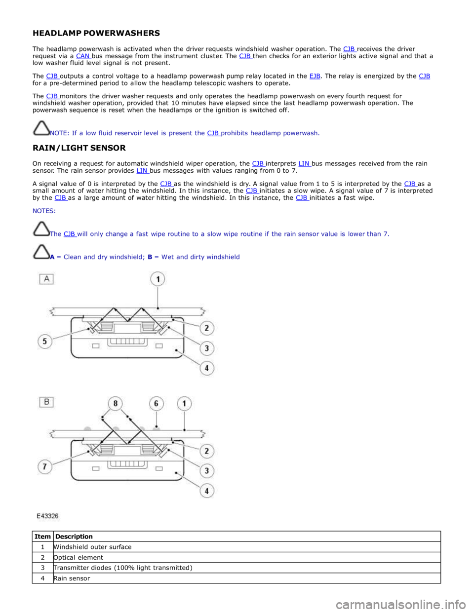
On receiving a request for automatic windshield wiper operation, the CJB interprets LIN bus messages received from the rain sensor. The rain sensor provides LIN bus messages with values ranging from 0 to 7.
A signal value of 0 is interpreted by the CJB as the windshield is dry. A signal value from 1 to 5 is interpreted by the CJB as a small amount of water hitting the windshield. In this instance, the CJB initiates a slow wipe. A signal value of 7 is interpreted by the CJB as a large amount of water hitting the windshield. In this instance, the CJB initiates a fast wipe. NOTES:
The CJB will only change a fast wipe routine to a slow wipe routine if the rain sensor value is lower than 7.
A = Clean and dry windshield; B = Wet and dirty windshield
Item Description 1 Windshield outer surface 2 Optical element 3 Transmitter diodes (100% light transmitted) 4 Rain sensor
Page 2542 of 3039
On vehicles with headlamp powerwash, each headlamp assembly is fitted with a headlamp powerwasher. The powerwasher is
located on the underside of the headlamp assembly. The powerwasher is located in a clip at the front of the headlamp and
secured with 2 self tapping screws to the headlamp body.
The powerwasher is a telescopic unit which extends forwards from the headlamp assembly under washer fluid pressure
supplied by the headlamp powerwash pump. When the pump pressure decreases the powerwasher is automatically retracted
back into the housing. The outer end of the powerwasher is fitted with a trim which blends the powerwasher into the headlamp
when it is not operating. The powerwasher has two washer jets which direct washer fluid under high pressure onto the
headlamp lens when the powerwasher is extended.
RAIN/LIGHT SENSOR
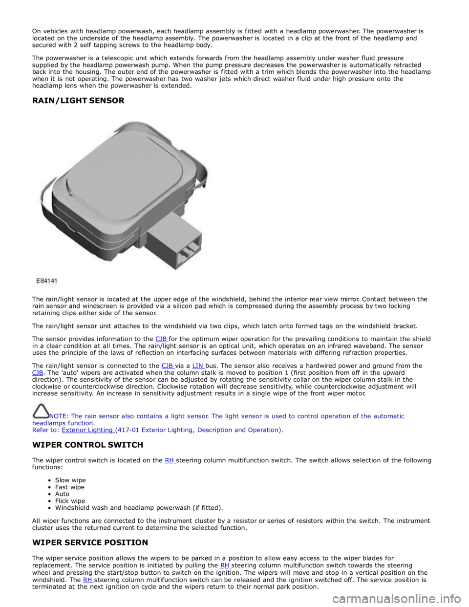
The rain/light sensor is located at the upper edge of the windshield, behind the interior rear view mirror. Contact between the
rain sensor and windscreen is provided via a silicon pad which is compressed during the assembly process by two locking
retaining clips either side of the sensor.
The rain/light sensor unit attaches to the windshield via two clips, which latch onto formed tags on the windshield bracket.
The sensor provides information to the CJB for the optimum wiper operation for the prevailing conditions to maintain the shield in a clear condition at all times. The rain/light sensor is an optical unit, which operates on an infrared waveband. The sensor
uses the principle of the laws of reflection on interfacing surfaces between materials with differing refraction properties.
The rain/light sensor is connected to the CJB via a LIN bus. The sensor also receives a hardwired power and ground from the CJB. The 'auto' wipers are activated when the column stalk is moved to position 1 (first position from off in the upward direction). The sensitivity of the sensor can be adjusted by rotating the sensitivity collar on the wiper column stalk in the
clockwise or counterclockwise direction. Clockwise rotation will decrease sensitivity, while counterclockwise adjustment will
increase sensitivity. An increase in sensitivity adjustment results in a single wipe of the front wiper motor.
NOTE: The rain sensor also contains a light sensor. The light sensor is used to control operation of the automatic
headlamps function.
Refer to: Exterior Lighting (417-01 Exterior Lighting, Description and Operation).
WIPER CONTROL SWITCH
The wiper control switch is located on the RH steering column multifunction switch. The switch allows selection of the following functions:
Slow wipe
Fast wipe
Auto
Flick wipe
Windshield wash and headlamp powerwash (if fitted).
All wiper functions are connected to the instrument cluster by a resistor or series of resistors within the switch. The instrument
cluster uses the returned current to determine the selected function.
WIPER SERVICE POSITION
The wiper service position allows the wipers to be parked in a position to allow easy access to the wiper blades for
replacement. The service position is initiated by pulling the RH steering column multifunction switch towards the steering wheel and pressing the start/stop button to switch on the ignition. The wipers will move and stop in a vertical position on the
windshield. The RH steering column multifunction switch can be released and the ignition switched off. The service position is terminated at the next ignition on cycle and the wipers return to their normal park position.