2010 JAGUAR XFR instrument cluster
[x] Cancel search: instrument clusterPage 2166 of 3039
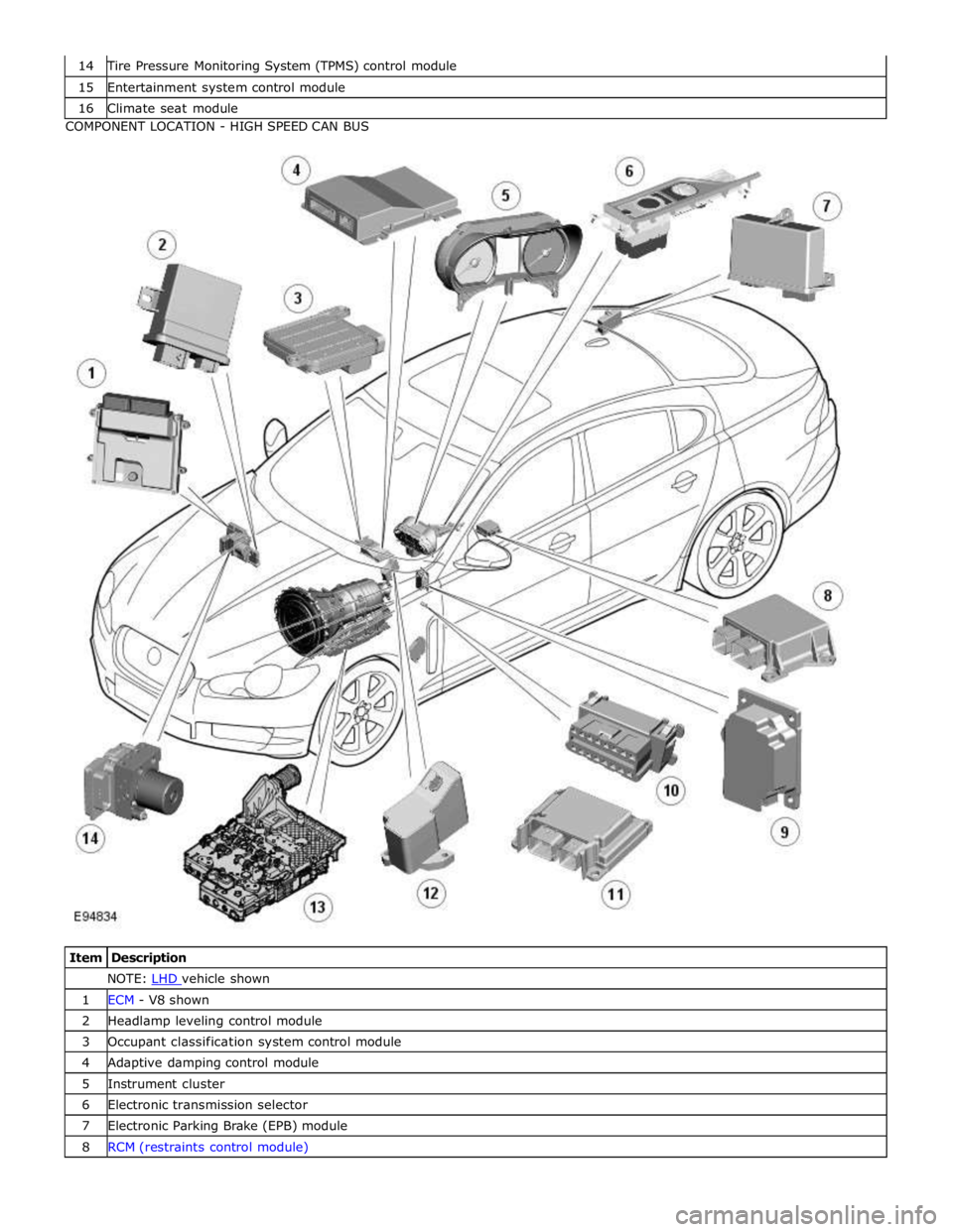
Tire Pressure Monitoring System (TPMS) control module 15 Entertainment system control module 16 Climate seat module COMPONENT LOCATION - HIGH SPEED CAN BUS
Item Description NOTE: LHD vehicle shown 1 ECM - V8 shown 2 Headlamp leveling control module 3 Occupant classification system control module 4 Adaptive damping control module 5 Instrument cluster 6 Electronic transmission selector 7 Electronic Parking Brake (EPB) module 8 RCM (restraints control module)
Page 2170 of 3039
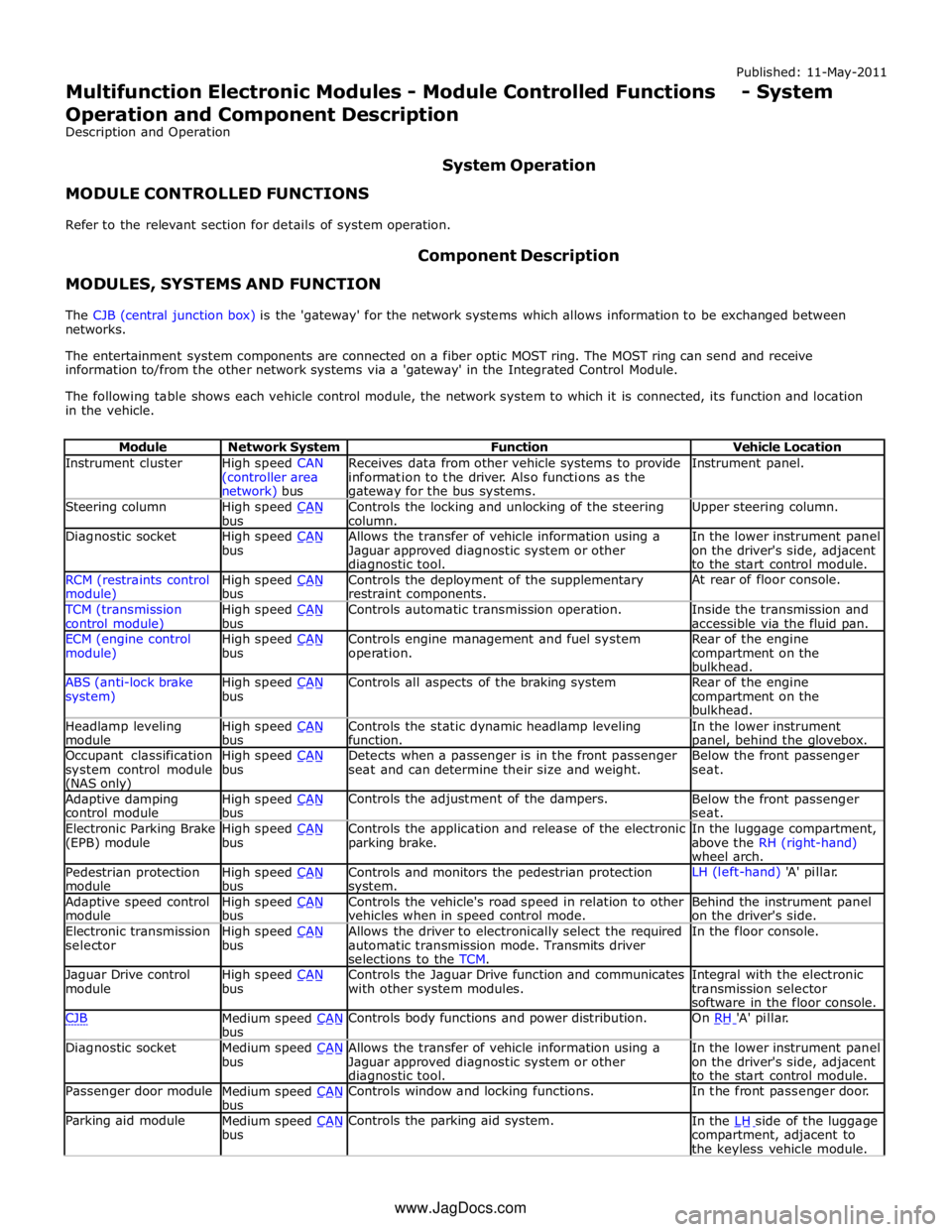
Instrument cluster
High speed CAN
(controller area network) bus Receives data from other vehicle systems to provide
information to the driver. Also functions as the gateway for the bus systems. Instrument panel. Steering column
High speed CAN bus Controls the locking and unlocking of the steering
column. Upper steering column. Diagnostic socket
High speed CAN bus Allows the transfer of vehicle information using a
Jaguar approved diagnostic system or other diagnostic tool. In the lower instrument panel
on the driver's side, adjacent
to the start control module. RCM (restraints control module) High speed CAN bus Controls the deployment of the supplementary
restraint components. At rear of floor console. TCM (transmission
control module) High speed CAN bus Controls automatic transmission operation.
Inside the transmission and
accessible via the fluid pan. ECM (engine control
module) High speed CAN bus Controls engine management and fuel system
operation. Rear of the engine
compartment on the
bulkhead. ABS (anti-lock brake
system) High speed CAN bus Controls all aspects of the braking system
Rear of the engine
compartment on the
bulkhead. Headlamp leveling
module High speed CAN bus Controls the static dynamic headlamp leveling
function. In the lower instrument panel, behind the glovebox. Occupant classification
system control module (NAS only) High speed CAN bus Detects when a passenger is in the front passenger
seat and can determine their size and weight. Below the front passenger
seat. Adaptive damping
control module High speed CAN bus Controls the adjustment of the dampers.
Below the front passenger
seat. Electronic Parking Brake
(EPB) module High speed CAN bus Controls the application and release of the electronic
parking brake. In the luggage compartment,
above the RH (right-hand)
wheel arch. Pedestrian protection
module High speed CAN bus Controls and monitors the pedestrian protection system. LH (left-hand) 'A' pillar. Adaptive speed control
module High speed CAN bus Controls the vehicle's road speed in relation to other
vehicles when in speed control mode. Behind the instrument panel
on the driver's side. Electronic transmission
selector High speed CAN bus Allows the driver to electronically select the required
automatic transmission mode. Transmits driver
selections to the TCM. In the floor console. Jaguar Drive control
module High speed CAN bus Controls the Jaguar Drive function and communicates
with other system modules. Integral with the electronic
transmission selector
software in the floor console. CJB
Medium speed CAN bus Controls body functions and power distribution. On RH 'A' pillar. Diagnostic socket
Medium speed CAN bus Allows the transfer of vehicle information using a
Jaguar approved diagnostic system or other diagnostic tool. In the lower instrument panel
on the driver's side, adjacent
to the start control module. Passenger door module
Medium speed CAN bus Controls window and locking functions. In the front passenger door. Parking aid module
Medium speed CAN bus Controls the parking aid system.
In the LH side of the luggage compartment, adjacent to
the keyless vehicle module. www.JagDocs.com
Page 2171 of 3039
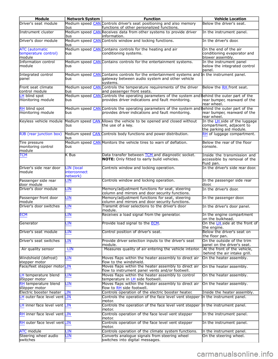
Module Network System Function Vehicle Location
Driver's seat module Medium speed CAN Controls driver's seat positioning and also memory Below the driver's seat. bus functions of other personalized functions.
Instrument cluster Medium speed CAN Receives data from other systems to provide driver In the instrument panel. bus information.
Driver's door module Medium speed CAN Controls window and locking functions. In the driver's door. bus
ATC (automatic Medium speed CAN Contains controls for the heating and air On the end of the air
temperature control)
module bus conditioning systems.
conditioning evaporator and
blower assembly.
Information control Medium speed CAN Contains controls for the entertainment systems. In the instrument panel module bus
below the integrated control
panel.
Integrated control Medium speed CAN Contains controls for the entertainment systems and In the instrument panel. panel bus
gateway between audio system and other vehicle
systems.
Front seat climate Medium speed CAN Controls the temperature requirements of the driver Below the RH front seat. control module bus and passenger front seats.
LH blind spot Medium speed CAN Controls the operating parameters of the system and Behind the outer part of the monitoring module bus provides driver indications and fault monitoring.
rear bumper, rearward of the
rear wheel.
RH blind spot Medium speed CAN Controls the operating parameters of the system and Behind the outer part of the monitoring module bus provides driver indications and fault monitoring.
rear bumper, rearward of the
rear wheel.
Keyless vehicle module Medium speed CAN Allows the vehicle to be opened and closed without In the LH side of the luggage bus the use of a key.
compartment, adjacent to
the parking aid module.
RJB (rear junction box) Medium speed CAN Controls body functions and power distribution. RH of luggage compartment. bus
Tire pressure Medium speed CAN Monitors the vehicle tires to warn of deflation. Below the rear of the floor monitoring control
module bus console.
TCM K Bus Data transfer between TCM and diagnostic socket. NOTE: Only fitted to early build vehicles. Inside the transmission and
accessible by removal of the
fluid pan.
Driver's side rear door
module LIN (local
interconnect
network) Controls window and locking operation. In the driver's side rear door.
Passenger side rear
door module LIN Controls window and locking operation. In the passenger side rear
door.
Driver's door module LIN Memory/adjustment functions for seat, steering
column and mirrors and door security functions. In the driver's door.
Passenger front door
module LIN Memory/adjustment functions for seat, steering
column and mirrors and door security functions. In the passenger door.
Driver's door switches LIN Transmit driver selections to the driver's door
module. In the driver's door panel.
ECM LIN Receives a load signal from the generator. In the engine compartment
on the bulkhead.
Generator LIN Provide load signal to the ECM. On the LH side at the front of the engine.
Driver's seat module LIN Control position of driver's seat. Below the driver's seat on
the floor pan.
Driver's seat switches LIN Provide driver selection inputs to the driver's seat
module. On the outside of the trim
panel on the driver's seat.
Air quality sensor LIN Measures quality of air entering the vehicle interior. At the front of the vehicle,
behind the air intake grill.
Windshield (defrost)
stepper motor LIN Moves flaps within the heater assembly to direct air
flow to the windshield. On the heater assembly.
Face/feet stepper motor LIN Moves flaps within the heater assembly to direct air
flow to instrument panel vents and/or footwell. On the heater assembly.
LH temperature blend
stepper motor
RH temperature blend
stepper motor LIN Moves flaps within the heater assembly to control
temperature in LH side footwell.
LIN Moves flaps within the heater assembly to direct air
flow to RH side footwell. On the heater assembly.
On the heater assembly.
Electric booster heater LIN Controls operation of the electric booster heater. Inside the heater assembly.
LH outer face level vent LIN Controls the operation of the face level vent stepper In the instrument panel.
motor.
LH inner face level vent LIN Controls the operation of the face level vent stepper In the instrument panel.
motor.
RH inner face level vent LIN Controls operation of the face level vent stepper
motor.
RH outer face level vent LIN Controls operation of the face level vent stepper
motor. In the instrument panel.
In the instrument panel.
ATC module LIN Controls operation of the climate system functions. In the instrument panel.
Steering wheel audio
switches LIN Converts analogue signals from steering wheel
switches into digital messages. On the steering wheel.
Page 2172 of 3039
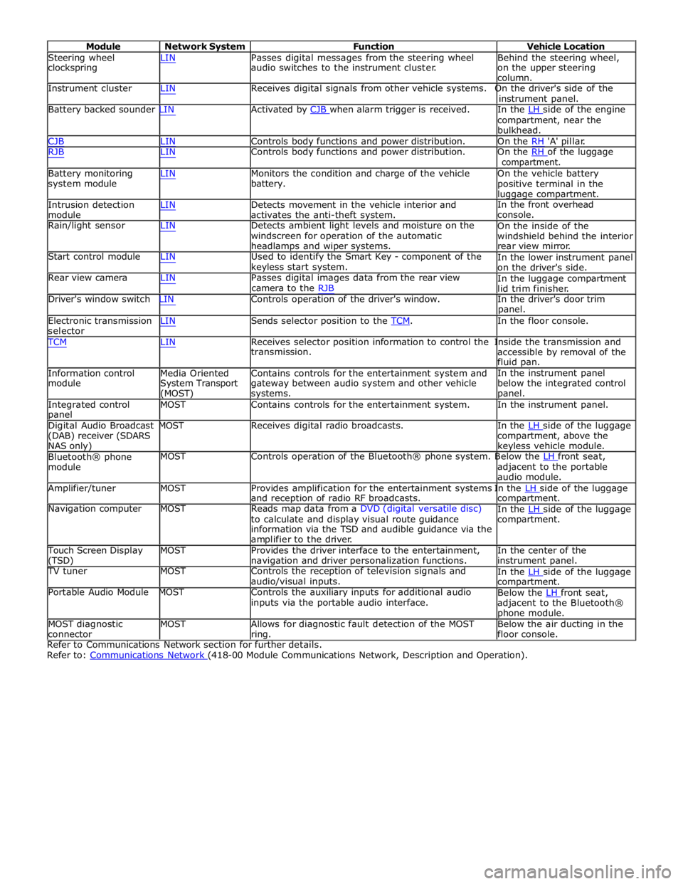
Module Network System Function Vehicle Location
Steering wheel
clockspring LIN Passes digital messages from the steering wheel
audio switches to the instrument cluster. Behind the steering wheel,
on the upper steering
column.
Instrument cluster LIN Receives digital signals from other vehicle systems. On the driver's side of the
instrument panel.
Battery backed sounder LIN Activated by CJB when alarm trigger is received. In the LH side of the engine compartment, near the
bulkhead.
CJB LIN Controls body functions and power distribution. On the RH 'A' pillar.
RJB LIN Controls body functions and power distribution. On the RH of the luggage compartment.
Battery monitoring
system module
Intrusion detection
module LIN Monitors the condition and charge of the vehicle
battery.
LIN Detects movement in the vehicle interior and
activates the anti-theft system. On the vehicle battery
positive terminal in the
luggage compartment.
In the front overhead
console.
Rain/light sensor LIN Detects ambient light levels and moisture on the
windscreen for operation of the automatic
headlamps and wiper systems.
Start control module LIN Used to identify the Smart Key - component of the
keyless start system.
Rear view camera LIN Passes digital images data from the rear view
camera to the RJB On the inside of the
windshield behind the interior
rear view mirror.
In the lower instrument panel
on the driver's side.
In the luggage compartment
lid trim finisher.
Driver's window switch LIN Controls operation of the driver's window. In the driver's door trim
panel.
Electronic transmission
selector LIN Sends selector position to the TCM. In the floor console. TCM LIN Receives selector position information to control the Inside the transmission and
Information control
module
Media Oriented
System Transport
(MOST) transmission.
Contains controls for the entertainment system and
gateway between audio system and other vehicle
systems. accessible by removal of the
fluid pan.
In the instrument panel
below the integrated control
panel.
Integrated control
panel MOST Contains controls for the entertainment system. In the instrument panel.
Digital Audio Broadcast MOST Receives digital radio broadcasts. In the LH side of the luggage (DAB) receiver (SDARS
NAS only)
Bluetooth® phone
module compartment, above the
keyless vehicle module.
MOST Controls operation of the Bluetooth® phone system. Below the LH front seat, adjacent to the portable
audio module.
Amplifier/tuner MOST Provides amplification for the entertainment systems In the LH side of the luggage and reception of radio RF broadcasts.
Navigation computer MOST Reads map data from a DVD (digital versatile disc)
to calculate and display visual route guidance
information via the TSD and audible guidance via the
amplifier to the driver. compartment.
In the LH side of the luggage compartment.
Touch Screen Display
(TSD) MOST Provides the driver interface to the entertainment,
navigation and driver personalization functions. In the center of the
instrument panel.
TV tuner MOST Controls the reception of television signals and
audio/visual inputs.
Portable Audio Module MOST Controls the auxiliary inputs for additional audio
inputs via the portable audio interface. In the LH side of the luggage compartment.
Below the LH front seat, adjacent to the Bluetooth®
phone module.
MOST diagnostic
connector MOST Allows for diagnostic fault detection of the MOST
ring. Below the air ducting in the
floor console.
Refer to Communications Network section for further details.
Refer to: Communications Network (418-00 Module Communications Network, Description and Operation).
Page 2180 of 3039

DTC Description Possible Cause Action B10CE24
Right Front Latch
Clutch Switch
Signal stuck high - button
stuck in active position Check for stuck right front door latch clutch switch. Refer to
the electrical circuit diagrams and check right front door
latch clutch switch circuit for short to ground B10CF24
Right Rear Latch
Clutch Switch
Signal stuck high - button
stuck in active position Check for stuck right rear door latch clutch switch. Refer to
the electrical circuit diagrams and check right rear door
latch clutch switch circuit for short to ground B10D124 Left Front Lock Button
Signal stuck high - button
stuck in active position Check for stuck left front door handle lock switch. Refer to
the electrical circuit diagrams and check left front door
handle lock switch circuit for short to ground B10D224 Left Rear Lock Button
Signal stuck high - button
stuck in active position Check for stuck left rear door handle lock switch. Refer to
the electrical circuit diagrams and check left rear door
handle lock switch circuit for short to ground B10D324
Right Front Lock
Button
Signal stuck high - button
stuck in active position Check for stuck right front door handle lock switch. Refer to
the electrical circuit diagrams and check right front door
handle lock switch circuit for short to ground B10D424
Right Rear Lock
Button
Signal stuck high - button
stuck in active position Check for stuck right rear door handle lock switch. Refer to
the electrical circuit diagrams and check left front door
handle lock switch circuit for short to ground U001000
Medium Speed CAN
Communication Bus
No subtype information Carry out any pinpoint tests associated with this DTC using
the manufacturer approved diagnostic system. Carry out
CAN network integrity test using the manufacturer approved diagnostic system U014000
Lost Communication
With Body Control
Module
Missing message from CJB Carry out any pinpoint tests associated with this DTC using
the manufacturer approved diagnostic system. Carry out
CAN network integrity test using the manufacturer
approved diagnostic system. Refer to the electrical circuit diagrams and check power and ground supplies to CJB U014200
Lost Communication
With Body Control
Module "B"
Missing message from RJB Carry out any pinpoint tests associated with this DTC using
the manufacturer approved diagnostic system. Carry out
CAN network integrity test using the manufacturer
approved diagnostic system. Refer to the electrical circuit diagrams and check power and ground supplies to RJB U015500
Lost Communication
With Instrument
Panel Cluster (IPC)
Control Module
Missing message from
instrument cluster Carry out any pinpoint tests associated with this DTC using
the manufacturer approved diagnostic system. Carry out
CAN network integrity test using the manufacturer
approved diagnostic system. Refer to the electrical circuit
diagrams and check power and ground supplies to
instrument cluster U030000
Internal Control
Module Software
Incompatibility
Invalid configuration
message is received Re-configure the RJB using the manufacturer approved
diagnostic system. Clear the DTC and retest. If the DTC is
still logged suspect the remote keyless entry module, refer
to the new module installation note at the top of the DTC
Index U201F00 External Receiver
No subtype information -
communication error Suspect the RF receiver, check and install a new RF receiver
as required, refer to the new module/component
installation note at top of DTC Index U201F13 External Receiver
Line open Refer to the electrical circuit diagrams and test RF receiver
communication circuit to remote keyless entry module for
short to ground or open circuit U201F87 External Receiver
Transmission error Refer to the electrical circuit diagrams and check the data
line between the RF receiver and the remote keyless entry
module for short, open circuit. Suspect the RF receiver or
remote keyless entry module, check and install a new RF
receiver or remote keyless entry module as required, refer
to the new module/component installation note at top of
DTC Index U210000
Initial Configuration
Not Complete
No subtype information Configure the Remote Keyless Entry module using the
manufacturer approved diagnostic system U210100
Control Module
Configuration Incompatible
No subtype information Re-configure the RJB using the manufacturer approved
diagnostic system U300049 Control Module
Internal electronic failure Install a new remote keyless entry module, refer to the
new module installation note at the top of the DTC Index U300281
Vehicle Identification
Number
Vehicle/component
mis-match. Module
previously installed to other
vehicle Install correct/new module to vehicle specification, refer to
the new module/component installation note at the top of
the DTC Index www.JagDocs.com
Page 2294 of 3039
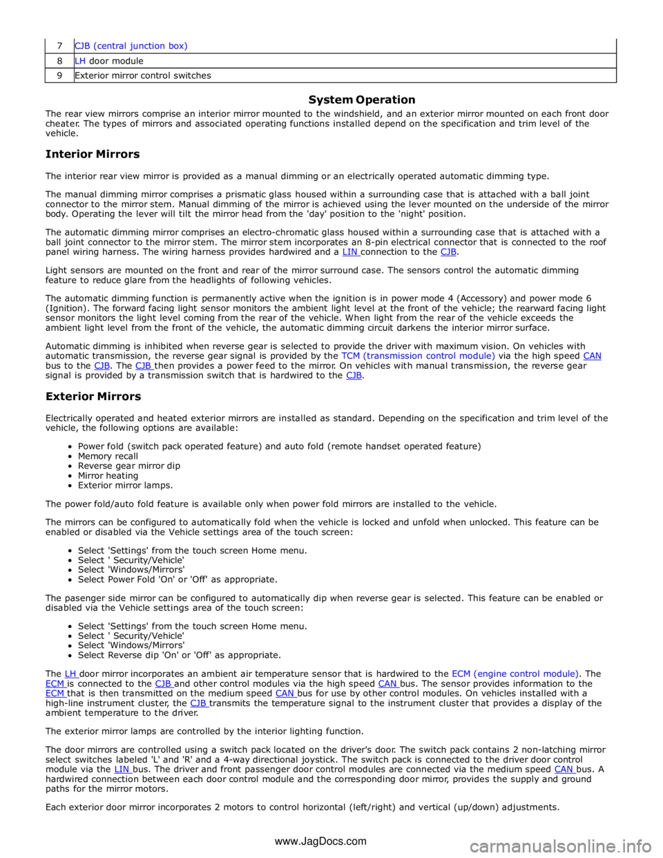
8 LH door module 9 Exterior mirror control switches
System Operation
The rear view mirrors comprise an interior mirror mounted to the windshield, and an exterior mirror mounted on each front door
cheater. The types of mirrors and associated operating functions installed depend on the specification and trim level of the
vehicle.
Interior Mirrors
The interior rear view mirror is provided as a manual dimming or an electrically operated automatic dimming type.
The manual dimming mirror comprises a prismatic glass housed within a surrounding case that is attached with a ball joint
connector to the mirror stem. Manual dimming of the mirror is achieved using the lever mounted on the underside of the mirror
body. Operating the lever will tilt the mirror head from the 'day' position to the 'night' position.
The automatic dimming mirror comprises an electro-chromatic glass housed within a surrounding case that is attached with a
ball joint connector to the mirror stem. The mirror stem incorporates an 8-pin electrical connector that is connected to the roof
panel wiring harness. The wiring harness provides hardwired and a LIN connection to the CJB.
Light sensors are mounted on the front and rear of the mirror surround case. The sensors control the automatic dimming
feature to reduce glare from the headlights of following vehicles.
The automatic dimming function is permanently active when the ignition is in power mode 4 (Accessory) and power mode 6
(Ignition). The forward facing light sensor monitors the ambient light level at the front of the vehicle; the rearward facing light
sensor monitors the light level coming from the rear of the vehicle. When light from the rear of the vehicle exceeds the
ambient light level from the front of the vehicle, the automatic dimming circuit darkens the interior mirror surface.
Automatic dimming is inhibited when reverse gear is selected to provide the driver with maximum vision. On vehicles with
automatic transmission, the reverse gear signal is provided by the TCM (transmission control module) via the high speed CAN bus to the CJB. The CJB then provides a power feed to the mirror. On vehicles with manual transmission, the reverse gear signal is provided by a transmission switch that is hardwired to the CJB.
Exterior Mirrors
Electrically operated and heated exterior mirrors are installed as standard. Depending on the specification and trim level of the
vehicle, the following options are available:
Power fold (switch pack operated feature) and auto fold (remote handset operated feature)
Memory recall
Reverse gear mirror dip
Mirror heating
Exterior mirror lamps.
The power fold/auto fold feature is available only when power fold mirrors are installed to the vehicle.
The mirrors can be configured to automatically fold when the vehicle is locked and unfold when unlocked. This feature can be
enabled or disabled via the Vehicle settings area of the touch screen:
Select 'Settings' from the touch screen Home menu.
Select ' Security/Vehicle'
Select 'Windows/Mirrors'
Select Power Fold 'On' or 'Off' as appropriate.
The pasenger side mirror can be configured to automatically dip when reverse gear is selected. This feature can be enabled or
disabled via the Vehicle settings area of the touch screen:
Select 'Settings' from the touch screen Home menu.
Select ' Security/Vehicle'
Select 'Windows/Mirrors'
Select Reverse dip 'On' or 'Off' as appropriate.
The LH door mirror incorporates an ambient air temperature sensor that is hardwired to the ECM (engine control module). The ECM is connected to the CJB and other control modules via the high speed CAN bus. The sensor provides information to the ECM that is then transmitted on the medium speed CAN bus for use by other control modules. On vehicles installed with a high-line instrument cluster, the CJB transmits the temperature signal to the instrument cluster that provides a display of the ambient temperature to the driver.
The exterior mirror lamps are controlled by the interior lighting function.
The door mirrors are controlled using a switch pack located on the driver's door. The switch pack contains 2 non-latching mirror
select switches labeled 'L' and 'R' and a 4-way directional joystick. The switch pack is connected to the driver door control
module via the LIN bus. The driver and front passenger door control modules are connected via the medium speed CAN bus. A hardwired connection between each door control module and the corresponding door mirror, provides the supply and ground
paths for the mirror motors.
Each exterior door mirror incorporates 2 motors to control horizontal (left/right) and vertical (up/down) adjustments. www.JagDocs.com
Page 2295 of 3039
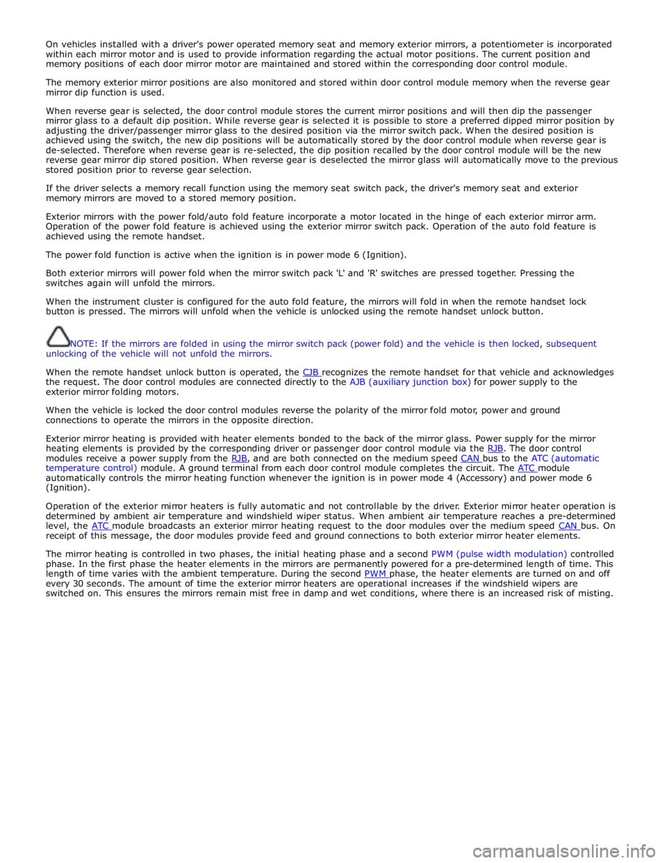
On vehicles installed with a driver's power operated memory seat and memory exterior mirrors, a potentiometer is incorporated
within each mirror motor and is used to provide information regarding the actual motor positions. The current position and
memory positions of each door mirror motor are maintained and stored within the corresponding door control module.
The memory exterior mirror positions are also monitored and stored within door control module memory when the reverse gear
mirror dip function is used.
When reverse gear is selected, the door control module stores the current mirror positions and will then dip the passenger
mirror glass to a default dip position. While reverse gear is selected it is possible to store a preferred dipped mirror position by
adjusting the driver/passenger mirror glass to the desired position via the mirror switch pack. When the desired position is
achieved using the switch, the new dip positions will be automatically stored by the door control module when reverse gear is
de-selected. Therefore when reverse gear is re-selected, the dip position recalled by the door control module will be the new
reverse gear mirror dip stored position. When reverse gear is deselected the mirror glass will automatically move to the previous
stored position prior to reverse gear selection.
If the driver selects a memory recall function using the memory seat switch pack, the driver's memory seat and exterior
memory mirrors are moved to a stored memory position.
Exterior mirrors with the power fold/auto fold feature incorporate a motor located in the hinge of each exterior mirror arm.
Operation of the power fold feature is achieved using the exterior mirror switch pack. Operation of the auto fold feature is
achieved using the remote handset.
The power fold function is active when the ignition is in power mode 6 (Ignition).
Both exterior mirrors will power fold when the mirror switch pack 'L' and 'R' switches are pressed together. Pressing the
switches again will unfold the mirrors.
When the instrument cluster is configured for the auto fold feature, the mirrors will fold in when the remote handset lock
button is pressed. The mirrors will unfold when the vehicle is unlocked using the remote handset unlock button.
NOTE: If the mirrors are folded in using the mirror switch pack (power fold) and the vehicle is then locked, subsequent
unlocking of the vehicle will not unfold the mirrors.
When the remote handset unlock button is operated, the CJB recognizes the remote handset for that vehicle and acknowledges the request. The door control modules are connected directly to the AJB (auxiliary junction box) for power supply to the
exterior mirror folding motors.
When the vehicle is locked the door control modules reverse the polarity of the mirror fold motor, power and ground
connections to operate the mirrors in the opposite direction.
Exterior mirror heating is provided with heater elements bonded to the back of the mirror glass. Power supply for the mirror
heating elements is provided by the corresponding driver or passenger door control module via the RJB. The door control modules receive a power supply from the RJB, and are both connected on the medium speed CAN bus to the ATC (automatic temperature control) module. A ground terminal from each door control module completes the circuit. The ATC module automatically controls the mirror heating function whenever the ignition is in power mode 4 (Accessory) and power mode 6
(Ignition).
Operation of the exterior mirror heaters is fully automatic and not controllable by the driver. Exterior mirror heater operation is
determined by ambient air temperature and windshield wiper status. When ambient air temperature reaches a pre-determined
level, the ATC module broadcasts an exterior mirror heating request to the door modules over the medium speed CAN bus. On receipt of this message, the door modules provide feed and ground connections to both exterior mirror heater elements.
The mirror heating is controlled in two phases, the initial heating phase and a second PWM (pulse width modulation) controlled
phase. In the first phase the heater elements in the mirrors are permanently powered for a pre-determined length of time. This
length of time varies with the ambient temperature. During the second PWM phase, the heater elements are turned on and off every 30 seconds. The amount of time the exterior mirror heaters are operational increases if the windshield wipers are
switched on. This ensures the mirrors remain mist free in damp and wet conditions, where there is an increased risk of misting.
Page 2329 of 3039
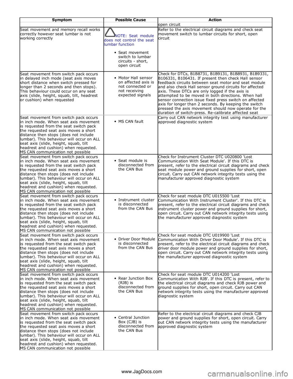
Symptom Possible Cause Action open circuit Seat movement and memory recall works
correctly however seat lumbar is not
working correctly
NOTE: Seat module
does not control the seat
lumbar function
Seat movement
switch to lumbar
circuits - short,
open circuit Refer to the electrical circuit diagrams and check seat
movement switch to lumbar circuits for short, open
circuit Seat movement from switch pack occurs
in delayed inch mode (seat axis moves
short distance when switch pressed for
longer than 2 seconds and then stops). This behaviour could occur on any seat
axis (slide, height, squab, tilt, headrest
or cushion) when requested
Motor Hall sensor
on affected axis is
not connected or
not receiving
expected signals Check for DTCs, B1B8731, B1B9131, B1B8931, B1B9331,
B106331, B106431. If present then check Hall sensor
feedback circuits between seat motor and seat module
and also check Hall sensor ground circuits for affected
axis. These DTCs are only logged if the axis is
attempted to be moved in both directions. When hall
sensor connection issue fixed press switch on affected
axis for longer than 2 seconds. By keeping the switch
pressed the axis movement should now operate for the
duration of switch-press. Re-calibrate affected seat Seat movement from switch pack occurs
in inch mode. When seat axis movement
is requested from the seat switch pack
the requested seat axis moves a short
distance then stops (does not include
lumbar). This behaviour will occur on ALL
seat axis (slide, height, squab, tilt
headrest and cushion) when requested.
MS CAN communication not possible
MS CAN fault Carry out CAN network integrity test using manufacturer
approved diagnostic system Seat movement from switch pack occurs
in inch mode. When seat axis movement
is requested from the seat switch pack
the requested seat axis moves a short
distance then stops (does not include
lumbar). This behaviour will occur on ALL
seat axis (slide, height, squab, tilt
headrest and cushion) when requested.
MS CAN communication not possible
Seat module is
disconnected from
the CAN Bus Check for Instrument Cluster DTC U020800 'Lost
Communication With Seat Module'. If this DTC is
present, refer to the electrical circuit diagrams and check
seat module power and ground supplies for short, open
circuit. Carry out CAN network integrity tests using the
manufacturer approved diagnostic system Seat movement from switch pack occurs
in inch mode. When seat axis movement
is requested from the seat switch pack
the requested seat axis moves a short
distance then stops (does not include
lumbar). This behaviour will occur on ALL
seat axis (slide, height, squab, tilt
headrest and cushion) when requested.
MS CAN communication not possible
Instrument cluster
is disconnected
from the CAN Bus Check for seat module DTC U015500 'Lost
Communication With Instrument Cluster'. If this DTC is
present, refer to the electrical circuit diagrams and check
instrument cluster power and ground supplies for short,
open circuit. Carry out CAN network integrity tests using
the manufacturer approved diagnostic system Seat movement from switch pack occurs
in inch mode. When seat axis movement
is requested from the seat switch pack
the requested seat axis moves a short
distance then stops (does not include
lumbar). This behaviour will occur on ALL
seat axis (slide, height, squab, tilt
headrest and cushion) when requested.
MS CAN communication not possible
Driver Door Module
is disconnected
from the CAN Bus Check for seat module DTC U019900 'Lost
Communication With Driver Door Module'. If this DTC is
present, refer to the electrical circuit diagrams and check
driver door module power and ground supplies for short,
open circuit. Carry out CAN network integrity tests using
the manufacturer approved diagnostic system Seat movement from switch pack occurs
in inch mode. When seat axis movement
is requested from the seat switch pack
the requested seat axis moves a short
distance then stops (does not include
lumbar). This behaviour will occur on ALL
seat axis (slide, height, squab, tilt
headrest and cushion) when requested.
MS CAN communication not possible
Rear Junction Box
(RJB) is
disconnected from
the CAN Bus Check for seat module DTC U014200 'Lost
Communication With RJB'. If this DTC is present, refer to
the electrical circuit diagrams and check RJB power and
ground supplies for short, open circuit. Carry out CAN
network integrity tests using the manufacturer approved
diagnostic system Seat movement from switch pack occurs
in inch mode. When seat axis movement
is requested from the seat switch pack
the requested seat axis moves a short
distance then stops (does not include
lumbar). This behaviour will occur on ALL
seat axis (slide, height, squab, tilt
headrest and cushion) when requested.
MS CAN communication not possible
Central Junction
Box (CJB) is
disconnected from
the CAN Bus Refer to the electrical circuit diagrams and check CJB
power and ground supplies for short, open circuit. Carry
out CAN network integrity tests using the manufacturer
approved diagnostic system www.JagDocs.com