2010 JAGUAR XFR instrument cluster
[x] Cancel search: instrument clusterPage 1912 of 3039
transmits the calculated voltage to the generator and regulator on the LIN bus connection.
The ECM will over-ride the voltage value requested by the battery monitoring system if it detects a fault in the generator and regulator. The ECM also signals the instrument cluster to display a warning message if it detects a fault with the generator and regulator. For additionalinformation refer to Instrument Cluster 413-01.
GENERATOR AND REGULATOR Component Description
The regulator provides a controlled variable voltage output from the generator. Two electrical terminals are provided on the
outer casing of the generator. One terminal supplies the DC (direct current) voltage output from the generator to the battery
positive terminal. The second terminal provides the LIN bus connection between the regulator and the ECM. www.JagDocs.com
Page 1940 of 3039
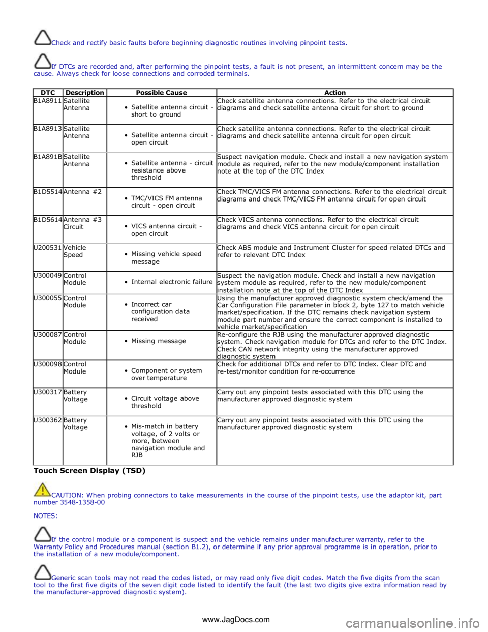
Check and rectify basic faults before beginning diagnostic routines involving pinpoint tests.
If DTCs are recorded and, after performing the pinpoint tests, a fault is not present, an intermittent concern may be the
cause. Always check for loose connections and corroded terminals.
DTC Description Possible Cause Action B1A8911
Satellite
Antenna
Satellite antenna circuit -
short to ground Check satellite antenna connections. Refer to the electrical circuit
diagrams and check satellite antenna circuit for short to ground B1A8913
Satellite
Antenna
Satellite antenna circuit -
open circuit Check satellite antenna connections. Refer to the electrical circuit
diagrams and check satellite antenna circuit for open circuit B1A891B
Satellite
Antenna
Satellite antenna - circuit
resistance above
threshold Suspect navigation module. Check and install a new navigation system
module as required, refer to the new module/component installation
note at the top of the DTC Index B1D5514 Antenna #2
TMC/VICS FM antenna
circuit - open circuit Check TMC/VICS FM antenna connections. Refer to the electrical circuit
diagrams and check TMC/VICS FM antenna circuit for open circuit B1D5614
Antenna #3
Circuit
VICS antenna circuit -
open circuit Check VICS antenna connections. Refer to the electrical circuit
diagrams and check VICS antenna circuit for open circuit U200531
Vehicle
Speed
Missing vehicle speed
message Check ABS module and Instrument Cluster for speed related DTCs and
refer to relevant DTC Index U300049
Control
Module
Internal electronic failure Suspect the navigation module. Check and install a new navigation
system module as required, refer to the new module/component
installation note at the top of the DTC Index U300055
Control
Module
Incorrect car
configuration data
received Using the manufacturer approved diagnostic system check/amend the
Car Configuration File parameter in block 2, byte 127 to match vehicle
market/specification. If the DTC remains check navigation system
module part number and ensure the correct component is installed to
vehicle market/specification U300087
Control
Module
Missing message Re-configure the RJB using the manufacturer approved diagnostic
system. Check navigation module for DTCs and refer to the DTC Index.
Check CAN network integrity using the manufacturer approved diagnostic system U300098
Control
Module
Component or system
over temperature Check for additional DTCs and refer to DTC Index. Clear DTC and
re-test/monitor condition for re-occurrence U300317
Battery
Voltage
Circuit voltage above
threshold Carry out any pinpoint tests associated with this DTC using the
manufacturer approved diagnostic system U300362
Battery
Voltage
Mis-match in battery
voltage, of 2 volts or
more, between
navigation module and
RJB Carry out any pinpoint tests associated with this DTC using the
manufacturer approved diagnostic system Touch Screen Display (TSD)
CAUTION: When probing connectors to take measurements in the course of the pinpoint tests, use the adaptor kit, part
number 3548-1358-00
NOTES:
If the control module or a component is suspect and the vehicle remains under manufacturer warranty, refer to the
Warranty Policy and Procedures manual (section B1.2), or determine if any prior approval programme is in operation, prior to
the installation of a new module/component.
Generic scan tools may not read the codes listed, or may read only five digit codes. Match the five digits from the scan
tool to the first five digits of the seven digit code listed to identify the fault (the last two digits give extra information read by
the manufacturer-approved diagnostic system).
www.JagDocs.com
Page 1948 of 3039
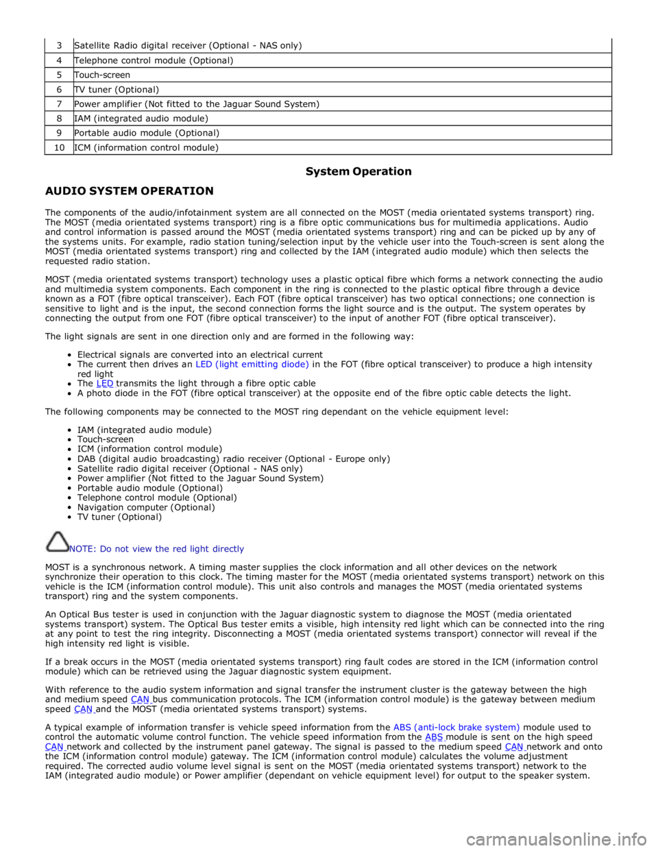
3 Satellite Radio digital receiver (Optional - NAS only) 4 Telephone control module (Optional) 5 Touch-screen 6 TV tuner (Optional) 7 Power amplifier (Not fitted to the Jaguar Sound System) 8 IAM (integrated audio module) 9 Portable audio module (Optional) 10 ICM (information control module)
AUDIO SYSTEM OPERATION System Operation
The components of the audio/infotainment system are all connected on the MOST (media orientated systems transport) ring.
The MOST (media orientated systems transport) ring is a fibre optic communications bus for multimedia applications. Audio
and control information is passed around the MOST (media orientated systems transport) ring and can be picked up by any of
the systems units. For example, radio station tuning/selection input by the vehicle user into the Touch-screen is sent along the
MOST (media orientated systems transport) ring and collected by the IAM (integrated audio module) which then selects the
requested radio station.
MOST (media orientated systems transport) technology uses a plastic optical fibre which forms a network connecting the audio
and multimedia system components. Each component in the ring is connected to the plastic optical fibre through a device
known as a FOT (fibre optical transceiver). Each FOT (fibre optical transceiver) has two optical connections; one connection is
sensitive to light and is the input, the second connection forms the light source and is the output. The system operates by
connecting the output from one FOT (fibre optical transceiver) to the input of another FOT (fibre optical transceiver).
The light signals are sent in one direction only and are formed in the following way:
Electrical signals are converted into an electrical current
The current then drives an LED (light emitting diode) in the FOT (fibre optical transceiver) to produce a high intensity
red light
The LED transmits the light through a fibre optic cable A photo diode in the FOT (fibre optical transceiver) at the opposite end of the fibre optic cable detects the light.
The following components may be connected to the MOST ring dependant on the vehicle equipment level:
IAM (integrated audio module)
Touch-screen
ICM (information control module)
DAB (digital audio broadcasting) radio receiver (Optional - Europe only)
Satellite radio digital receiver (Optional - NAS only)
Power amplifier (Not fitted to the Jaguar Sound System)
Portable audio module (Optional)
Telephone control module (Optional)
Navigation computer (Optional)
TV tuner (Optional)
NOTE: Do not view the red light directly
MOST is a synchronous network. A timing master supplies the clock information and all other devices on the network
synchronize their operation to this clock. The timing master for the MOST (media orientated systems transport) network on this
vehicle is the ICM (information control module). This unit also controls and manages the MOST (media orientated systems
transport) ring and the system components.
An Optical Bus tester is used in conjunction with the Jaguar diagnostic system to diagnose the MOST (media orientated
systems transport) system. The Optical Bus tester emits a visible, high intensity red light which can be connected into the ring
at any point to test the ring integrity. Disconnecting a MOST (media orientated systems transport) connector will reveal if the
high intensity red light is visible.
If a break occurs in the MOST (media orientated systems transport) ring fault codes are stored in the ICM (information control
module) which can be retrieved using the Jaguar diagnostic system equipment.
With reference to the audio system information and signal transfer the instrument cluster is the gateway between the high
and medium speed CAN bus communication protocols. The ICM (information control module) is the gateway between medium speed CAN and the MOST (media orientated systems transport) systems.
A typical example of information transfer is vehicle speed information from the ABS (anti-lock brake system) module used to
control the automatic volume control function. The vehicle speed information from the ABS module is sent on the high speed CAN network and collected by the instrument panel gateway. The signal is passed to the medium speed CAN network and onto the ICM (information control module) gateway. The ICM (information control module) calculates the volume adjustment
required. The corrected audio volume level signal is sent on the MOST (media orientated systems transport) network to the
IAM (integrated audio module) or Power amplifier (dependant on vehicle equipment level) for output to the speaker system.
Page 1975 of 3039
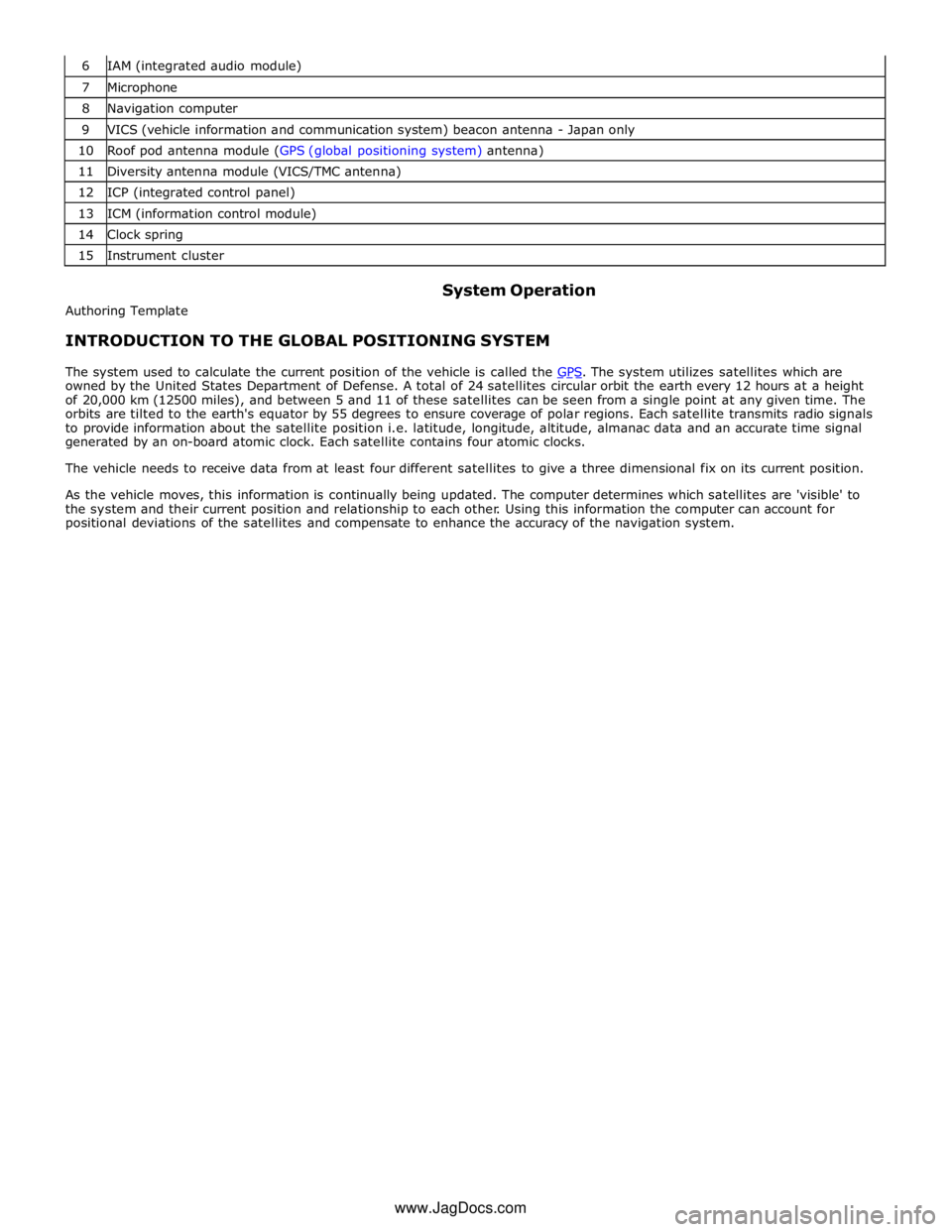
7 Microphone 8 Navigation computer 9 VICS (vehicle information and communication system) beacon antenna - Japan only 10 Roof pod antenna module (GPS (global positioning system) antenna) 11 Diversity antenna module (VICS/TMC antenna) 12 ICP (integrated control panel) 13 ICM (information control module) 14 Clock spring 15 Instrument cluster
Authoring Template System Operation
INTRODUCTION TO THE GLOBAL POSITIONING SYSTEM
The system used to calculate the current position of the vehicle is called the GPS. The system utilizes satellites which are owned by the United States Department of Defense. A total of 24 satellites circular orbit the earth every 12 hours at a height
of 20,000 km (12500 miles), and between 5 and 11 of these satellites can be seen from a single point at any given time. The
orbits are tilted to the earth's equator by 55 degrees to ensure coverage of polar regions. Each satellite transmits radio signals
to provide information about the satellite position i.e. latitude, longitude, altitude, almanac data and an accurate time signal
generated by an on-board atomic clock. Each satellite contains four atomic clocks.
The vehicle needs to receive data from at least four different satellites to give a three dimensional fix on its current position.
As the vehicle moves, this information is continually being updated. The computer determines which satellites are 'visible' to
the system and their current position and relationship to each other. Using this information the computer can account for
positional deviations of the satellites and compensate to enhance the accuracy of the navigation system.
www.JagDocs.com
Page 2024 of 3039
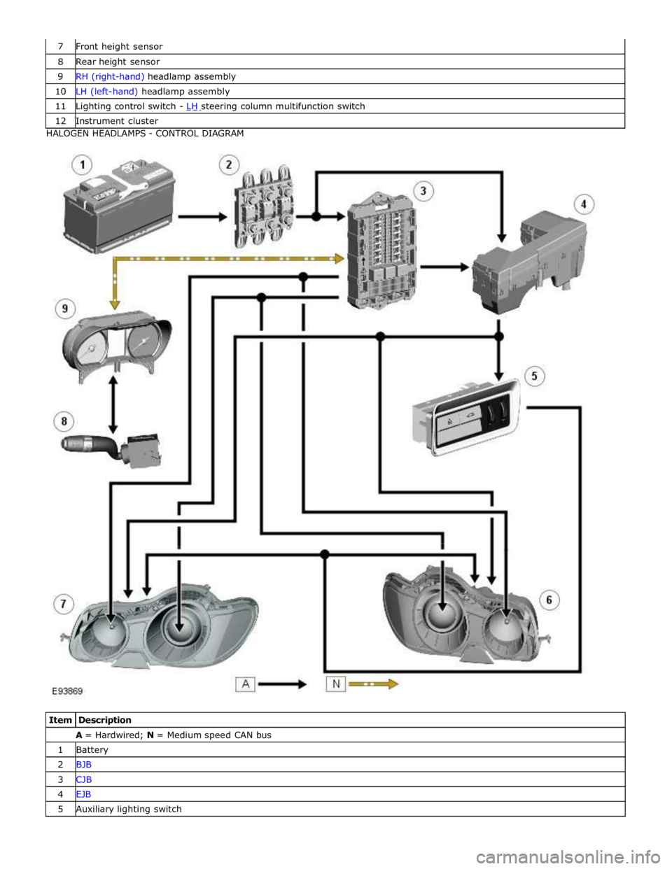
8 Rear height sensor 9 RH (right-hand) headlamp assembly 10 LH (left-hand) headlamp assembly 11 Lighting control switch - LH steering column multifunction switch 12 Instrument cluster HALOGEN HEADLAMPS - CONTROL DIAGRAM
Item Description A = Hardwired; N = Medium speed CAN bus 1 Battery 2 BJB 3 CJB 4 EJB 5 Auxiliary lighting switch
Page 2025 of 3039
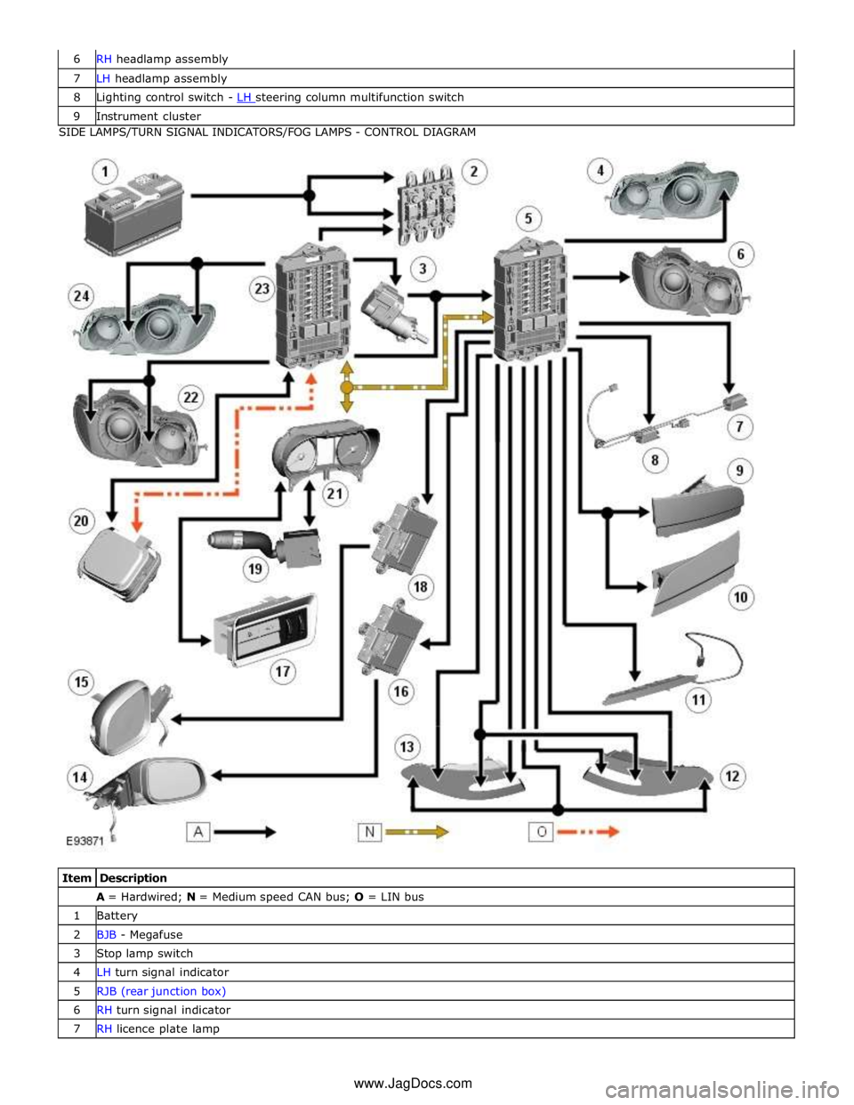
7 LH headlamp assembly 8 Lighting control switch - LH steering column multifunction switch 9 Instrument cluster SIDE LAMPS/TURN SIGNAL INDICATORS/FOG LAMPS - CONTROL DIAGRAM
Item Description A = Hardwired; N = Medium speed CAN bus; O = LIN bus 1 Battery 2 BJB - Megafuse 3 Stop lamp switch 4 LH turn signal indicator 5 RJB (rear junction box) 6 RH turn signal indicator 7 RH licence plate lamp www.JagDocs.com
Page 2026 of 3039
8 LH licence plate lamp 9 LH fog lamp 10 RH fog lamp 11 High mounted stop lamp 12 RH tail lamp assembly 13 LH tail lamp assembly 14 RH door mirror side repeater 15 LH door mirror side repeater 16 RH front door module 17 Auxiliary lighting switch 18 LH front door module 19 Lighting control switch - LH steering column multifunction switch 20 Rain/light sensor 21 Instrument cluster 22 RH headlamp assembly - side lamp and side marker lamp (if fitted) 23 CJB 24 LH headlamp assembly - side lamp and side marker lamp (if fitted)
System Operation CENTRAL JUNCTION BOX (CJB) AND REAR JUNCTION BOX (RJB)
The CJB is an integrated unit which controls body functions and power distribution. The CJB is located on the RH 'A' pillar. The RJB also controls body functions and power distribution and is located in the RH side of the luggage compartment. Central Junction Box
The CJB receives inputs from the following switches via the instrument cluster and the medium speed CAN bus: LH Steering column multifunction switch - Side lamp position
- Headlamp position
- Automatic (AUTO) position
- Timer delay positions
- Turn signal indicators
- Headlamp flash and main beam positions.
The CJB receives direct inputs from the following components: Stop lamp switch
Rain/light sensor.
The CJB provides power supplies to the following lamps:
LH and RH front side lamps LH and RH front side marker lamps (if fitted) LH and RH static bending lamp (if fitted) LH and RH low beam headlamp LH and RH high beam headlamp. Rear Junction Box
The RJB provides power supplies to the following lamps:
LH and RH tail lamps LH and RH stop lamps LH and RH front turn signal indicators LH and RH rear turn signal indicators LH and RH licence plate lamps LH and RH side marker lamps High mounted stop lamp
Rear fog lamps
Reverse lamps.
The RJB also provides a power supply to the LH and RH door modules. The door modules use the power supply to activate the turn signal indicator side repeater lamps located in the door mirrors, on receipt of a medium speed CAN bus message from the RJB. Circuit Protection
The CJB and the RJB provide circuit protection for their respective lighting circuits. The exterior lighting circuits are protected
Page 2027 of 3039
by Field Effect Transistors (FET's). The FET's can detect overloads and short circuits and respond to heat generated by
increased current flow caused by a short circuit.
On a normal conventionally protected circuit this would cause a fuse to blow. The FET's respond to the heat increase and
disconnect the power supply to the affected circuit. When the fault is rectified or the FET has cooled, the FET will reset and
operate the circuit normally. If the fault persists the FET will cycle, disconnecting and reconnecting the power supply.
The CJB and the RJB store fault codes which can be retrieved using a Jaguar approved diagnostic system. The fault code will identify that there is a fault on a particular output circuit which will assist with fault diagnosis and detection.
Alarm Indications
The exterior lighting system is used for alarm arm and disarm requests to show alarm system status.
When the driver locks and arms the vehicle, a visual indication of a successful lock and arm request is displayed to the driver
by a single flash of the hazard flashers. If the vehicle is superlocked, then the hazard flashers will flash a second time (200 ms
off and 200 ms on) to confirm the superlock request.
If the alarm is activated, the hazard flashers are operated for 10, 30 second cycles of 200 ms on and 200 ms off, with a 10
second delay between each cycle.
NOTE: On North American Specification (NAS) vehicles, the delay between the cycle when the alarm is activated is 60
seconds.
Lights on Warning
When the ignition is in the off power mode 0 or accessory power mode 4 and the lighting control switch is in the side lamp or
headlamp position, a warning chime will sound if the driver's door is opened. This indicates to the driver that the exterior
lights have been left switched on.
The chime is generated from the instrument cluster sounder on receipt of a lights on signal, a driver's door open signal and an
ignition off power mode 0 or accessory power mode 4 signal via a medium speed CAN bus signal from the CJB. Headlamp Timer
The RJB controls the headlamp timer function which allows the headlamps to remain on for a period of time after leaving the vehicle. This is a driver convenience feature which illuminates the driveway after leaving the vehicle.
To operate the timer function the lighting control switch must be in one of the three headlamp timer positions when the
ignition status is changed from ignition on power mode 6 to the off power mode 0. The timer function will then be initiated and
the low beam headlamps will be illuminated for the selected timer period.
NOTE: If the lighting switch is in the AUTO position, the headlamp timer will not function when the ignition is changed to
off power mode 0.
When the lighting control switch is in the autolamp exit delay position, the lighting control switch reference voltage flows
through 4 of the resistors. The returned signal voltage is detected by the instrument cluster which outputs a message on the
medium speed CAN bus to the RJB that autolamps has been selected.
Depending on the selected exit delay position, the reference voltage to the autolamp exit delay switch is routed through 3, 2
or 1 resistors which is detected by the instrument cluster. The cluster outputs a message on the medium speed CAN bus to the RJB that autolamp exit delay period has been selected at 30, 60 or 120 seconds respectively. Crash Signal Activation
When a crash signal is transmitted from the RCM (restraints control module), the RJB activates the hazard flashers. The hazard flashers continue to operate until the ignition is in the off power mode 0 or accessory power mode 6. Once this ignition state
has occurred, the RCM will cease to transmit the crash signal.
LIGHTING CONTROL SWITCH
The instrument cluster outputs 2 reference voltages to the rotary lighting control switch; one feed being supplied to the light
selection function of the switch and the second feed being supplied to the auto headlamp exit delay function. The switch
position is determined by instrument cluster by the change in returned signal voltage which is routed through up to 4 resistors
in series depending on the selection made.
OFF - When the lighting control switch is in the off position, the reference voltage flows through 1 of the resistors. The
returned signal voltage is detected by the instrument cluster which outputs a message on the medium speed CAN bus to the CJB that no lighting selection is made. The reference voltage to the auto headlamp exit delay switch is routed through 4 resistors which is detected by the instrument cluster which outputs a message on the medium speed CAN bus to the CJB that auto headlamp or exit delay has not been selected.
SIDE LAMPS - When the lighting control switch is in the side lamp position, the reference voltage flows through 2 of the
resistors. The returned signal voltage is detected by the instrument cluster which outputs a message on the medium speed
CAN bus to the CJB to activate the side lamps. The reference voltage to the autolamp exit delay switch is routed through 4 resistors which is detected by the instrument cluster which outputs a message on the medium speed CAN bus to the CJB that auto headlamp or exit delay has not been selected.
HEADLAMPS - When the lighting control switch is in the headlamp position, the reference voltage flows through 3 of the