2010 JAGUAR XFR instrument cluster
[x] Cancel search: instrument clusterPage 1836 of 3039
Warning Devices - Warning Devices
Diagnosis and Testing
Principles of Operation Published: 29-Apr-2013
For a detailed description of the Blindspot Monitoring system, refer to the relevant Description and Operation sections in the
workshop manual. REFER to: (413-09 Warning Devices)
Blindspot Monitoring System (Description and Operation), Blindspot Monitoring System (Description and Operation), Blindspot Monitoring System (Description and Operation).
Inspection and Verification
CAUTION: Diagnosis by substitution from a donor vehicle is NOT acceptable. Substitution of control modules does not
guarantee confirmation of a fault, and may also cause additional faults in the vehicle being tested and/or the donor vehicle.
1. Verify the customer concern.
2. Visually inspect for obvious signs of damage and system integrity.
NOTE: Particular attention should be paid to the following items where DTCs may not be logged:
Check for contamination (e.g. dirt, grime, frosting, ice) around the blindspot monitoring sensors and clear.
Visual Inspection
Mechanical Electrical
Exterior rear view mirror glass
Mud or sleet contamination around rear bumper area
Blindspot Monitoring Modules
Fuse(s)
Relay(s)
Wiring Harness
Electrical connector(s)
Blindspot Monitoring Modules
3. If an obvious cause for an observed or reported concern is found, correct the cause (if possible) before proceeding to
the next step.
4. If the cause is not visually evident, verify the symptom and refer to the Symptom Chart, alternatively, check for
Diagnostic Trouble Codes (DTCs) and refer to the DTC Index.
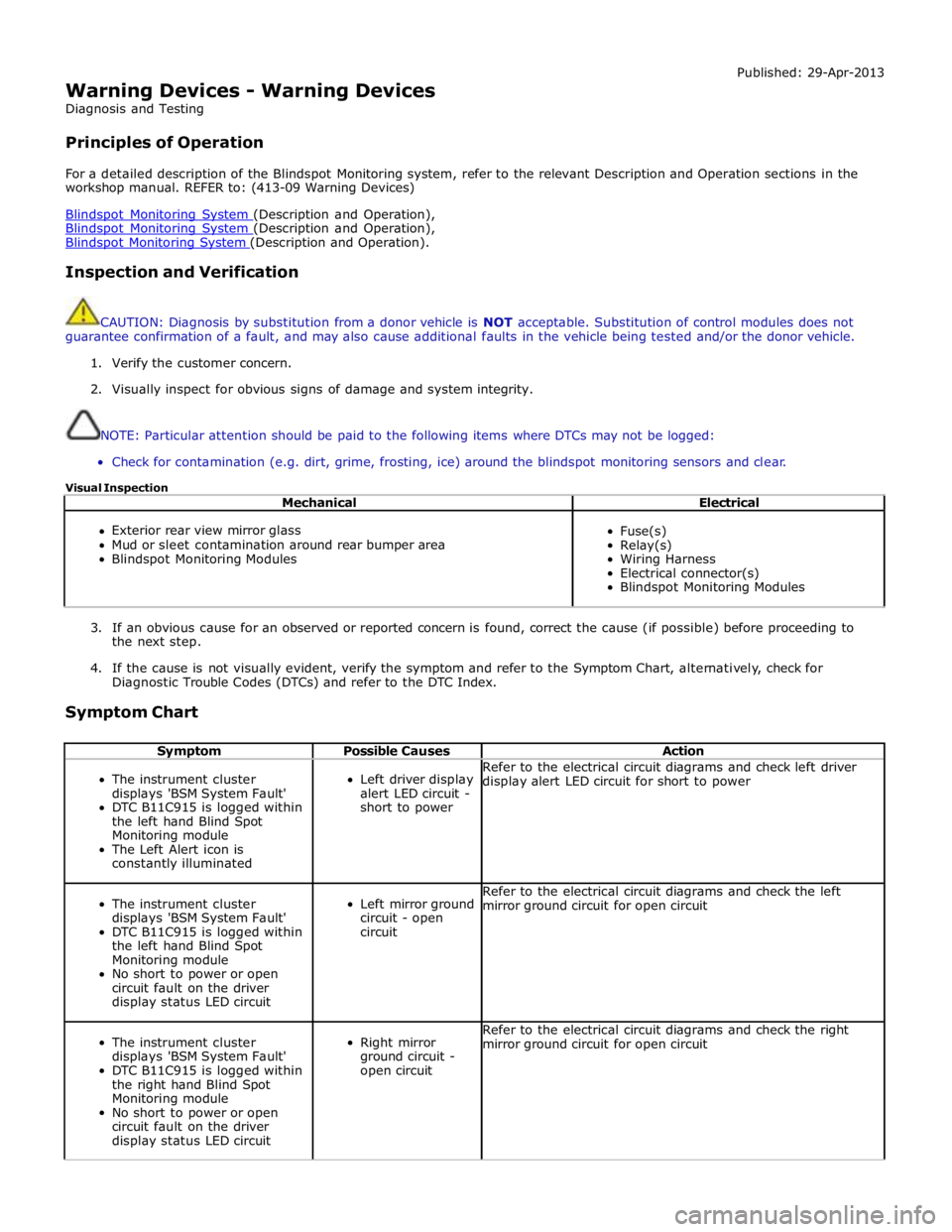
Symptom Chart
Symptom Possible Causes Action
The instrument cluster
displays 'BSM System Fault'
DTC B11C915 is logged within
the left hand Blind Spot
Monitoring module
The Left Alert icon is
constantly illuminated
Left driver display
alert LED circuit -
short to power Refer to the electrical circuit diagrams and check left driver
display alert LED circuit for short to power
The instrument cluster
displays 'BSM System Fault'
DTC B11C915 is logged within
the left hand Blind Spot
Monitoring module
No short to power or open
circuit fault on the driver
display status LED circuit
Left mirror ground
circuit - open
circuit Refer to the electrical circuit diagrams and check the left
mirror ground circuit for open circuit
The instrument cluster
displays 'BSM System Fault'
DTC B11C915 is logged within
the right hand Blind Spot
Monitoring module
No short to power or open
circuit fault on the driver
display status LED circuit
Right mirror
ground circuit -
open circuit Refer to the electrical circuit diagrams and check the right
mirror ground circuit for open circuit
Page 1837 of 3039
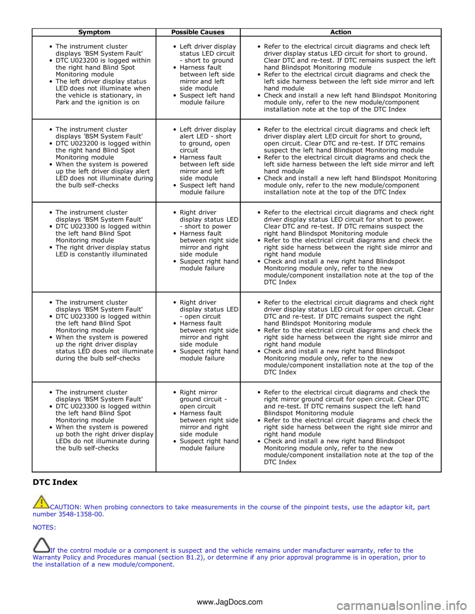
Symptom Possible Causes Action
The instrument cluster
displays 'BSM System Fault'
DTC U023200 is logged within
the right hand Blind Spot
Monitoring module
The left driver display status
LED does not illuminate when
the vehicle is stationary, in
Park and the ignition is on
Left driver display
status LED circuit
- short to ground
Harness fault
between left side
mirror and left
side module
Suspect left hand
module failure
Refer to the electrical circuit diagrams and check left
driver display status LED circuit for short to ground.
Clear DTC and re-test. If DTC remains suspect the left
hand Blindspot Monitoring module
Refer to the electrical circuit diagrams and check the
left side harness between the left side mirror and left
hand module
Check and install a new left hand Blindspot Monitoring
module only, refer to the new module/component
installation note at the top of the DTC Index
The instrument cluster
displays 'BSM System Fault'
DTC U023200 is logged within
the right hand Blind Spot
Monitoring module
When the system is powered
up the left driver display alert
LED does not illuminate during
the bulb self-checks
Left driver display
alert LED - short
to ground, open
circuit
Harness fault
between left side
mirror and left
side module
Suspect left hand
module failure
Refer to the electrical circuit diagrams and check left
driver display alert LED circuit for short to ground,
open circuit. Clear DTC and re-test. If DTC remains
suspect the left hand Blindspot Monitoring module
Refer to the electrical circuit diagrams and check the
left side harness between the left side mirror and left
hand module
Check and install a new left hand Blindspot Monitoring
module only, refer to the new module/component
installation note at the top of the DTC Index
The instrument cluster
displays 'BSM System Fault'
DTC U023300 is logged within
the left hand Blind Spot
Monitoring module
The right driver display status
LED is constantly illuminated
Right driver
display status LED
- short to power
Harness fault
between right side
mirror and right
side module
Suspect right hand
module failure
Refer to the electrical circuit diagrams and check right
driver display status LED circuit for short to power.
Clear DTC and re-test. If DTC remains suspect the
right hand Blindspot Monitoring module
Refer to the electrical circuit diagrams and check the
right side harness between the right side mirror and
right hand module
Check and install a new right hand Blindspot
Monitoring module only, refer to the new
module/component installation note at the top of the
DTC Index
The instrument cluster
displays 'BSM System Fault'
DTC U023300 is logged within
the left hand Blind Spot
Monitoring module
When the system is powered
up the right driver display
status LED does not illuminate
during the bulb self-checks
Right driver
display status LED
- open circuit
Harness fault
between right side
mirror and right
side module
Suspect right hand
module failure
Refer to the electrical circuit diagrams and check right
driver display status LED circuit for open circuit. Clear
DTC and re-test. If DTC remains suspect the right
hand Blindspot Monitoring module
Refer to the electrical circuit diagrams and check the
right side harness between the right side mirror and
right hand module
Check and install a new right hand Blindspot
Monitoring module only, refer to the new
module/component installation note at the top of the
DTC Index
The instrument cluster
displays 'BSM System Fault'
DTC U023300 is logged within
the left hand Blind Spot
Monitoring module
When the system is powered
up both the right driver display
LEDs do not illuminate during
the bulb self-checks
Right mirror
ground circuit -
open circuit
Harness fault
between right side
mirror and right
side module
Suspect right hand
module failure
Refer to the electrical circuit diagrams and check the
right mirror ground circuit for open circuit. Clear DTC
and re-test. If DTC remains suspect the left hand
Blindspot Monitoring module
Refer to the electrical circuit diagrams and check the
right side harness between the right side mirror and
right hand module
Check and install a new right hand Blindspot
Monitoring module only, refer to the new
module/component installation note at the top of the
DTC Index DTC Index
CAUTION: When probing connectors to take measurements in the course of the pinpoint tests, use the adaptor kit, part
number 3548-1358-00.
NOTES:
If the control module or a component is suspect and the vehicle remains under manufacturer warranty, refer to the
Warranty Policy and Procedures manual (section B1.2), or determine if any prior approval programme is in operation, prior to
the installation of a new module/component.
www.JagDocs.com
Page 1838 of 3039
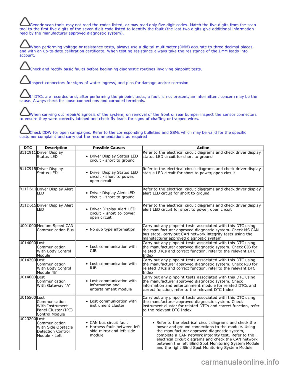
Generic scan tools may not read the codes listed, or may read only five digit codes. Match the five digits from the scan
tool to the first five digits of the seven digit code listed to identify the fault (the last two digits give additional information
read by the manufacturer approved diagnostic system).
When performing voltage or resistance tests, always use a digital multimeter (DMM) accurate to three decimal places,
and with an up-to-date calibration certificate. When testing resistance always take the resistance of the DMM leads into
account.
Check and rectify basic faults before beginning diagnostic routines involving pinpoint tests.
Inspect connectors for signs of water ingress, and pins for damage and/or corrosion.
If DTCs are recorded and, after performing the pinpoint tests, a fault is not present, an intermittent concern may be the
cause. Always check for loose connections and corroded terminals.
When carrying out repair/diagnosis of the system, on removal of the front or rear bumper inspect the sensor connectors
to ensure they were correctly latched and check fly leads for signs of chaffing or trapped wires.
Check DDW for open campaigns. Refer to the corresponding bulletins and SSMs which may be valid for the specific
customer complaint and carry out the recommendations as required
DTC Description Possible Causes Action B11C911
Driver Display
Status LED
Driver Display Status LED
circuit - short to ground Refer to the electrical circuit diagrams and check driver display
status LED circuit for short to ground B11C915
Driver Display
Status LED
Driver Display Status LED
circuit - short to power,
open circuit Refer to the electrical circuit diagrams and check driver display
status LED circuit for short to power, open circuit B11D611
Driver Display Alert
LED
Driver Display Alert LED
circuit - short to ground Refer to the electrical circuit diagrams and check driver display
alert LED circuit for short to ground B11D615
Driver Display Alert
LED
Driver Display Alert LED
circuit - short to power,
open circuit Refer to the electrical circuit diagrams and check driver display
alert LED circuit for short to power, open circuit U001000
Medium Speed CAN
Communication Bus
No sub type information Carry out any pinpoint tests associated with this DTC using
the manufacturer approved diagnostic system. Check MS CAN
bus state, carry out CAN network integrity tests using the
manufacturer approved diagnostic system U014000
Lost
Communication
With Body Control
Module
Lost communication with
CJB Carry out any pinpoint tests associated with this DTC using
the manufacturer approved diagnostic system. Check CJB for
related DTCs and correct function, refer to the relevant DTC
Index U014200
Lost
Communication
With Body Control
Module "B"
Lost communication with
RJB Carry out any pinpoint tests associated with this DTC using
the manufacturer approved diagnostic system. Check RJB for
related DTCs and correct function, refer to the relevant DTC
Index U014600
Lost
Communication
With Gateway "A"
Lost communication with
information and
entertainment module Carry out any pinpoint tests associated with this DTC using
the manufacturer approved diagnostic system. Check
information and entertainment module for related DTCs and
correct function, refer to the relevant DTC Index U015500
Lost
Communication
With Instrument
Panel Cluster (IPC)
Control Module
Lost communication with
instrument cluster Carry out any pinpoint tests associated with this DTC using
the manufacturer approved diagnostic system. Check
instrument cluster for related DTCs and correct function, refer
to the relevant DTC Index U023200
Lost
Communication
With Side Obstacle
Detection Control
Module - Left
CAN bus circuit fault
Harness fault between left
side mirror and left side
module
Refer to the electrical circuit diagrams and check the
power and ground connections to the module. Using
the manufacturer approved diagnostic system,
complete a CAN network integrity test. Refer to the
electrical circuit diagrams and check the CAN network
between the left Blind Spot Monitoring System Module
and the right Blind Spot Monitoring System Module
Page 1839 of 3039
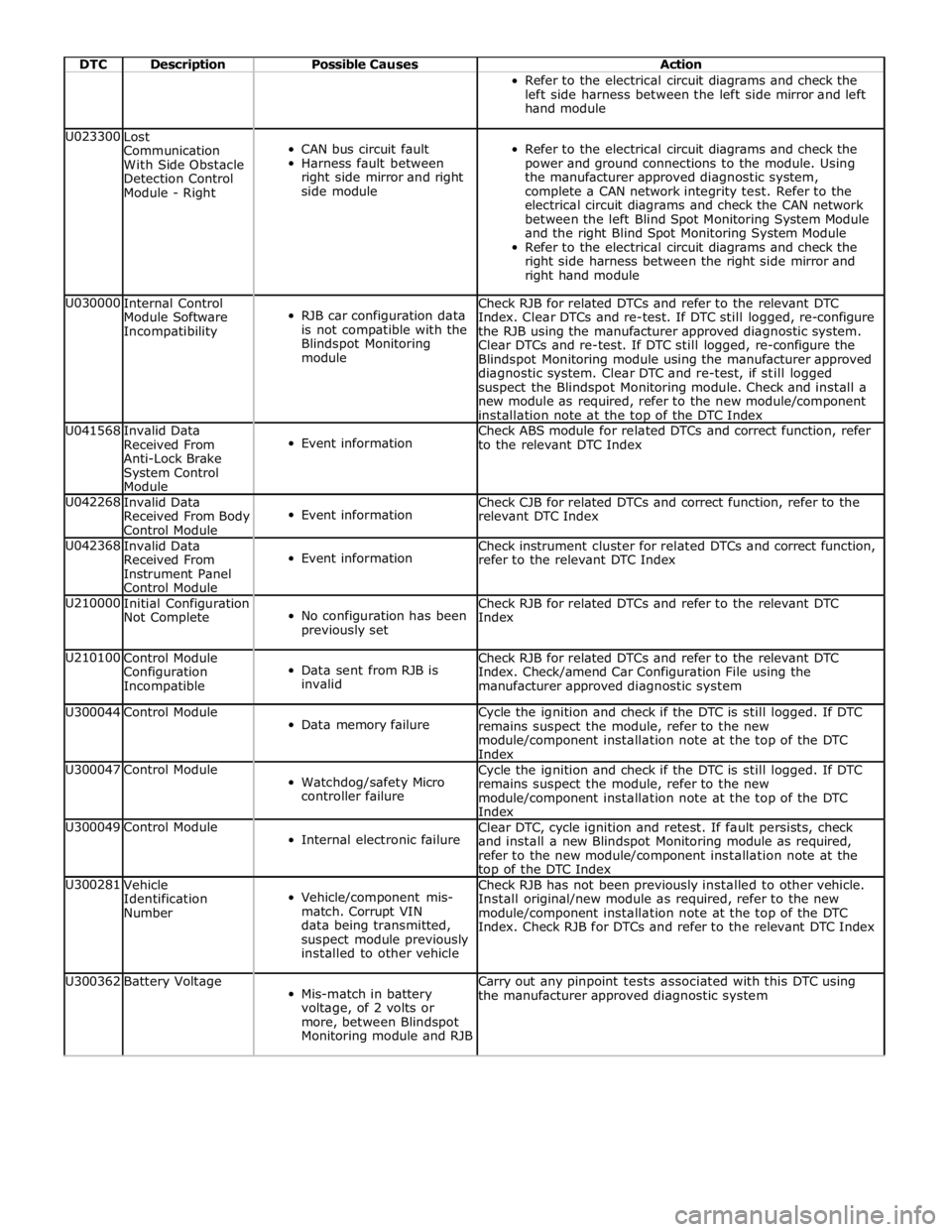
DTC Description Possible Causes Action Refer to the electrical circuit diagrams and check the
left side harness between the left side mirror and left
hand module U023300
Lost
Communication
With Side Obstacle
Detection Control
Module - Right
CAN bus circuit fault
Harness fault between
right side mirror and right
side module
Refer to the electrical circuit diagrams and check the
power and ground connections to the module. Using
the manufacturer approved diagnostic system,
complete a CAN network integrity test. Refer to the
electrical circuit diagrams and check the CAN network
between the left Blind Spot Monitoring System Module
and the right Blind Spot Monitoring System Module
Refer to the electrical circuit diagrams and check the
right side harness between the right side mirror and
right hand module U030000
Internal Control
Module Software
Incompatibility
RJB car configuration data
is not compatible with the
Blindspot Monitoring
module Check RJB for related DTCs and refer to the relevant DTC
Index. Clear DTCs and re-test. If DTC still logged, re-configure
the RJB using the manufacturer approved diagnostic system.
Clear DTCs and re-test. If DTC still logged, re-configure the
Blindspot Monitoring module using the manufacturer approved
diagnostic system. Clear DTC and re-test, if still logged
suspect the Blindspot Monitoring module. Check and install a
new module as required, refer to the new module/component
installation note at the top of the DTC Index U041568
Invalid Data
Received From
Anti-Lock Brake
System Control
Module
Event information Check ABS module for related DTCs and correct function, refer
to the relevant DTC Index U042268
Invalid Data
Received From Body
Control Module
Event information Check CJB for related DTCs and correct function, refer to the
relevant DTC Index U042368
Invalid Data
Received From
Instrument Panel
Control Module
Event information Check instrument cluster for related DTCs and correct function,
refer to the relevant DTC Index U210000
Initial Configuration
Not Complete
No configuration has been
previously set Check RJB for related DTCs and refer to the relevant DTC
Index U210100
Control Module
Configuration
Incompatible
Data sent from RJB is
invalid Check RJB for related DTCs and refer to the relevant DTC
Index. Check/amend Car Configuration File using the
manufacturer approved diagnostic system U300044 Control Module
Data memory failure Cycle the ignition and check if the DTC is still logged. If DTC
remains suspect the module, refer to the new
module/component installation note at the top of the DTC
Index U300047 Control Module
Watchdog/safety Micro
controller failure Cycle the ignition and check if the DTC is still logged. If DTC
remains suspect the module, refer to the new
module/component installation note at the top of the DTC
Index U300049 Control Module
Internal electronic failure Clear DTC, cycle ignition and retest. If fault persists, check
and install a new Blindspot Monitoring module as required,
refer to the new module/component installation note at the top of the DTC Index U300281
Vehicle
Identification
Number
Vehicle/component mis-
match. Corrupt VIN
data being transmitted,
suspect module previously
installed to other vehicle Check RJB has not been previously installed to other vehicle.
Install original/new module as required, refer to the new
module/component installation note at the top of the DTC
Index. Check RJB for DTCs and refer to the relevant DTC Index U300362 Battery Voltage
Mis-match in battery
voltage, of 2 volts or
more, between Blindspot
Monitoring module and RJB Carry out any pinpoint tests associated with this DTC using
the manufacturer approved diagnostic system
Page 1850 of 3039
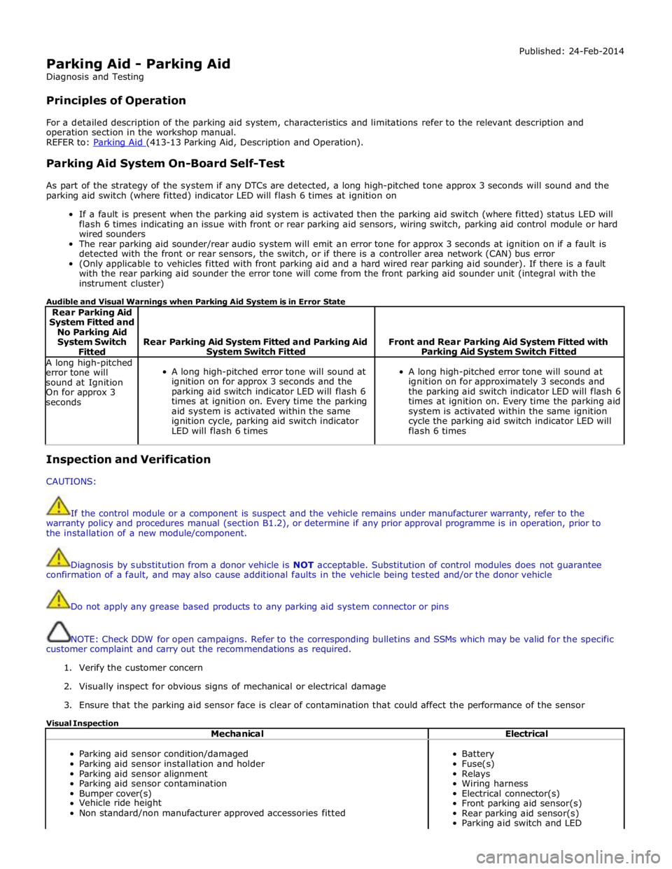
Parking Aid - Parking Aid
Diagnosis and Testing
Principles of Operation Published: 24-Feb-2014
For a detailed description of the parking aid system, characteristics and limitations refer to the relevant description and
operation section in the workshop manual.
REFER to: Parking Aid (413-13 Parking Aid, Description and Operation).
Parking Aid System On-Board Self-Test
As part of the strategy of the system if any DTCs are detected, a long high-pitched tone approx 3 seconds will sound and the
parking aid switch (where fitted) indicator LED will flash 6 times at ignition on
If a fault is present when the parking aid system is activated then the parking aid switch (where fitted) status LED will
flash 6 times indicating an issue with front or rear parking aid sensors, wiring switch, parking aid control module or hard
wired sounders
The rear parking aid sounder/rear audio system will emit an error tone for approx 3 seconds at ignition on if a fault is
detected with the front or rear sensors, the switch, or if there is a controller area network (CAN) bus error
(Only applicable to vehicles fitted with front parking aid and a hard wired rear parking aid sounder). If there is a fault
with the rear parking aid sounder the error tone will come from the front parking aid sounder unit (integral with the
instrument cluster)
Audible and Visual Warnings when Parking Aid System is in Error State
Rear Parking Aid
System Fitted and
No Parking Aid
System Switch
Fitted
Rear Parking Aid System Fitted and Parking Aid System Switch Fitted
Front and Rear Parking Aid System Fitted with Parking Aid System Switch Fitted A long high-pitched
error tone will
sound at Ignition
On for approx 3
seconds
A long high-pitched error tone will sound at
ignition on for approx 3 seconds and the
parking aid switch indicator LED will flash 6
times at ignition on. Every time the parking
aid system is activated within the same
ignition cycle, parking aid switch indicator
LED will flash 6 times
A long high-pitched error tone will sound at
ignition on for approximately 3 seconds and
the parking aid switch indicator LED will flash 6
times at ignition on. Every time the parking aid
system is activated within the same ignition
cycle the parking aid switch indicator LED will
flash 6 times Inspection and Verification
CAUTIONS:
If the control module or a component is suspect and the vehicle remains under manufacturer warranty, refer to the
warranty policy and procedures manual (section B1.2), or determine if any prior approval programme is in operation, prior to
the installation of a new module/component.
Diagnosis by substitution from a donor vehicle is NOT acceptable. Substitution of control modules does not guarantee
confirmation of a fault, and may also cause additional faults in the vehicle being tested and/or the donor vehicle
Do not apply any grease based products to any parking aid system connector or pins
NOTE: Check DDW for open campaigns. Refer to the corresponding bulletins and SSMs which may be valid for the specific
customer complaint and carry out the recommendations as required.
1. Verify the customer concern
2. Visually inspect for obvious signs of mechanical or electrical damage
3. Ensure that the parking aid sensor face is clear of contamination that could affect the performance of the sensor
Visual Inspection
Mechanical Electrical
Parking aid sensor condition/damaged
Parking aid sensor installation and holder
Parking aid sensor alignment
Parking aid sensor contamination
Bumper cover(s)
Vehicle ride height
Non standard/non manufacturer approved accessories fitted
Battery
Fuse(s)
Relays
Wiring harness
Electrical connector(s)
Front parking aid sensor(s)
Rear parking aid sensor(s)
Parking aid switch and LED
Page 1881 of 3039
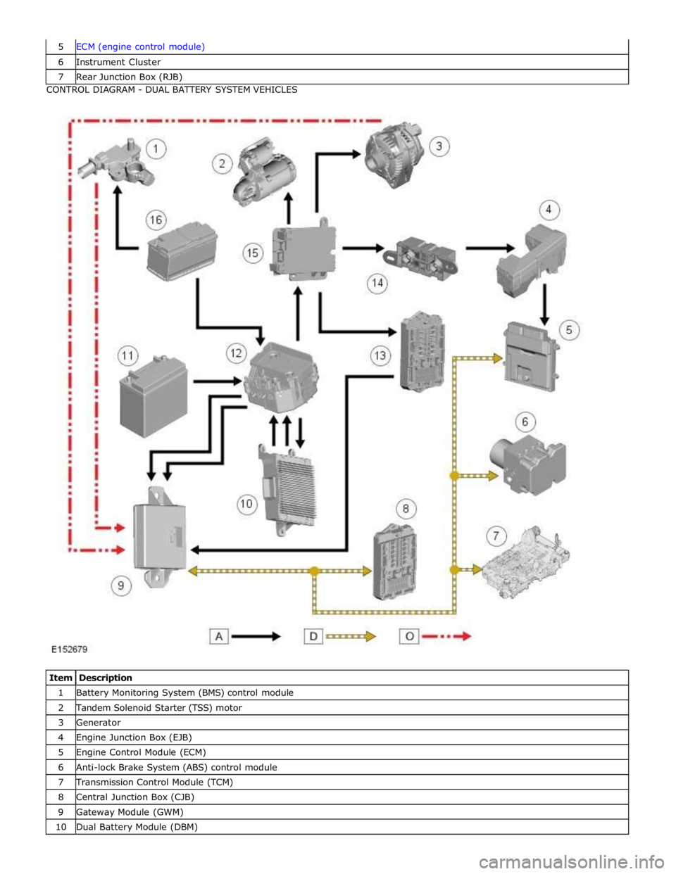
6 Instrument Cluster 7 Rear Junction Box (RJB) CONTROL DIAGRAM - DUAL BATTERY SYSTEM VEHICLES
Item Description 1 Battery Monitoring System (BMS) control module 2 Tandem Solenoid Starter (TSS) motor 3 Generator 4 Engine Junction Box (EJB) 5 Engine Control Module (ECM) 6 Anti-lock Brake System (ABS) control module 7 Transmission Control Module (TCM) 8 Central Junction Box (CJB) 9 Gateway Module (GWM) 10 Dual Battery Module (DBM)
Page 1885 of 3039

is operated to crank the engine. The GWM is connected to the ABS (Anti-lock Brake System) control module via the high speed
CAN bus. With the vehicle stationary and the engine off after an ECO engine stop, when the driver releases the brake pedal
the ABS control module senses the reduction in brake pressure. This change of brake pressure state is sent as a high speed
CAN message which is received by the GWM and the ECM. The GWM reacts within 105ms to instruct the DBM via the LIN bus
to operate the two contactors in the DBJB to supply the sensitive loads from the secondary battery and supply the TSS motor
direct from the primary battery.
When the engine is running and the generator is supplying power to the vehicle systems, the GWM again instructs the DBM to
operate the two contactors in the DBJB to supply all vehicle systems from the primary battery and the generator and to isolate
the secondary battery.
Secondary Battery Charging
The DBM also controls the charging of the secondary battery. The GWM contains electrical load management software and
monitors both batteries for their state of charge. The primary battery is monitored by the BMS control module which is
connected to the DBM via the LIN bus. The DBM communicates the primary battery condition to the GWM via a LIN bus
connection. The GWM sends a signal to the DBM via the LIN bus to instruct it to apply charging from the generator to the
secondary battery when required. The contactor 2 is closed by the DBJB to complete the secondary battery circuit, and the
generator output is applied to the secondary battery to charge it.
The generator output is controlled by the GWM which monitors and controls the electrical load management system. The
generator is connected to the GWM by a LIN bus allowing the GWM to control the output of the generator to maintain electrical
system load requirements and battery charging.
Electrical Load Management
The electrical load management is controlled by the GWM and the BMS control module.
The GWM will monitor the vehicle system power loads before and during an ECO engine stop.
Before an ECO engine stop, the GWM will transmit a signal to system control modules on the CAN bus to request a power save
on all electrical loads and set a minimum electrical value override. The GWM monitors the vehicle electrical loads and will
inhibit a ECO engine stop until the load current is at a value low enough to be supported by the secondary battery.
If the electrical loads cannot be reduced sufficiently, the GWM will inhibit the ECO engine stop.
When the engine is stopped after an ECO engine stop, the GWM will continue to monitor the primary battery state of charge.
If the primary or secondary battery voltage falls below 11.0V, a level which will result in degraded starting performance or
possible primary battery damage, the GWM will initiate an engine start.
System Inhibits
The ECO stop/start system is inhibited if the dual battery system is not be capable of preventing electrical loads on the
vehicle being subject to unacceptably low voltage levels during ECO stop/start operations due to a fault.
ECO stop/start inhibit monitoring of the primary battery is performed by the BMS control module. If the primary battery voltage
is too low to support an ECO stop/start, then the BMS control module will send a message to the GWM on the LIN bus to
suspend ECO stop/start.
The GWM monitors the secondary battery and the dual battery system components. Any fault found will cause the GWM to
inhibit ECO stop/start and the GWM will record a DTC (diagnostic trouble code).
Fault Diagnosis
The GWM performs passive and active diagnostics on the dual battery system to determine the status of the system
components.
Passive diagnostics can detect faults in the DBJB and can check for stuck open or closed contactors and failure of DBM
contactor command signals.
Active diagnostics is a routine to test the capability of the contactors to respond to open or close command signals sent from
the GWM to the DBM. This routine also checks the FET's (Field Effect Transistors) activate as required. (Refer to Dual Battery
Junction Box below for description of FET operation)
The GWM will also check the dual battery system components for faults in a controlled environment when the generator is
providing a charging output. This will ensure that the detection of a fault will not result in sensitive electrical loads being
subjected to low voltage which may occur during an ECO stop/start with a fault present.
The GWM will illuminate the charge warning indicator in the instrument cluster if fault is detected in the dual battery system
which will result in a degraded power supply.
If a fault is detected the GWM transmits a CAN message to inhibit ECO stop/start operation. In some cases it will record a
DTC, display a warning message in instrument cluster and also illuminate charge warning indicator.
PRIMARY BATTERY - ALL VEHICLES Component Description
The primary battery is located in a plastic tray under the luggage compartment floor in the right side of the luggage
compartment, adjacent to the spare wheel. The battery is vented via a tube which is connected with a T piece to the vent from
Page 1911 of 3039
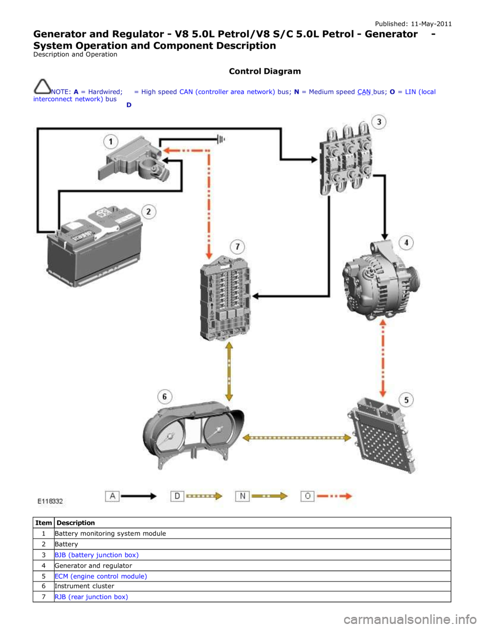
Published: 11-May-2011
Generator and Regulator - V8 5.0L Petrol/V8 S/C 5.0L Petrol - Generator - System Operation and Component Description
Description and Operation
Control Diagram
NOTE: A = Hardwired;
interconnect network) bus
D = High speed CAN (controller area network) bus; N = Medium speed CAN bus; O = LIN (local
Item Description 1 Battery monitoring system module 2 Battery 3 BJB (battery junction box) 4 Generator and regulator 5 ECM (engine control module) 6 Instrument cluster 7 RJB (rear junction box)