2010 JAGUAR XFR remote control
[x] Cancel search: remote controlPage 782 of 3039
16 Ball (12 off) 17 Distance keeper 18 Crash tube The column comprises a cast magnesium mounting bracket which provides the attachment to the cross-beam. Attached to the
mounting bracket is a rake lever which is attached to the mounting bracket at the lower end with two pivot bearings. The
bearings allow the rake lever to rotate upwards or downward to adjust the column rake.
The rake lever also provides for the attachment of the rake housing which can slide within the lever to provide the reach
adjustment. Within the rake housing is the axial housing which is supported on each side with 6 ball bearings which allow the
rake housing to move forward or backwards. The bearings on each side are arranged in groups of 3 bearings and are separated
by a distance keeper which allows the housing to supported on bearings along its length. Within the axial housing is a tube
which is supported at the upper end of the column on the upper bearing. The tube has a central splined hole which provides for
the fitment of the splined shaft. The splined shaft can slide within the tube on the splines when the column reach is adjusted
or the column collapses in a crash condition. The splined shaft also passes rotary motion from the steering wheel through the
length of the column to the outer clamping yoke which is supported on the lower bearing.
The electric steering column lock is attached to the top of the rake lever. A lock bolt within the steering column lock engages in
one of 8 slots in the locking sleeve located at the lower end of the column preventing rotation of the steering wheel. The
locking sleeve is retained by a tolerance ring which in turn is located on the outer diameter of the tube yoke. The tolerance
ring allows a specified amount of torque to be applied to the splined shaft before it slips, preventing damage to the column
lock due to excessive force being applied to the steering wheel when the lock is engaged. The tolerance ring is designed to
slip on the splined shaft when the applied torque exceeds the fitted slip load of 200 Nm minimum. Repeated rotation of the
lock collar will reduce its slipping torque to 100 Nm minimum. The lock is controlled by the CJB.
A steering angle sensor is located at the upper end of the steering column and is attached to the crash adaptor. The sensor
measures steering rotation via a toothed wheel located on the splined tube at the upper end of the column. The sensor
receives a power supply from the CJB and supplies 2 signals (A and B) relating to the steering rotation to the ABS (anti-lock brake system) module. The module transmits this data on the high speed CAN bus for use by other vehicle systems. Refer to: Anti-Lock Control - Stability Assist (206-09 Anti-Lock Control - Stability Assist, Description and Operation).
The steering column is adjustable electrically, for reach and rake. The adjustment mechanism comprises an electric adjustment
motor, a lead screw, a rake solenoid, a reach solenoid, a reach clutch and a rake clutch. The column adjustment is controlled
manually using a joystick switch located on the LH (left-hand) side of the column lower cowl. The joystick can be moved
forward and backward to adjust the column reach in and out and moved up and down to adjust the rake. The switch selection
energizes the adjustment motor in the applicable direction and also engages the applicable solenoid and clutch.
When the joystick switch is rotated to the 'auto' position, the steering column will adjust to the uppermost rake position when
the ignition is switched off. It will re-adjust to the position corresponding to the memory position for the remote handset when
the ignition is switched on.
The memory function of the electric column is linked to and controlled by the driver's seat module. The module provides for the
storage of three separate memory positions which are stored against 3 individual remote handsets.
Refer to: Seats (501-10 Seating, Description and Operation).
The steering wheel locates on a splined shaft in the upper column assembly and is secured with a bolt. The steering wheel
houses the driver's airbag and switches for the audio system, gear change and speed control. A clockspring is used to connect
the steering wheel electrical components to the vehicle harness.
Two plastic shrouds are fitted to the upper column assembly. The lower shroud is fitted with an energy absorbing foam pad to
minimize leg injury in the event of an accident.
www.JagDocs.com
Page 803 of 3039

automatically reset once the applicable remote handset has been detected by the vehicle security systems.
STEERING WHEEL HEATER
On certain models the rim of the steering wheel contains a heater element. Operation of the heater is selected using the
Touch Screen Display (TSD).
The heater temperature is controlled by a heated steering wheel control module located within the steering wheel. Power for
the heater element is supplied to the steering wheel via 2 contacts on the clockspring and a slip ring mounted on the steering
wheel.
Page 1805 of 3039

DTC Description Possible Cause Action U013900
Lost
Communication
with Suspension
Control Module 'B'
Loss of CAN communication
with adaptive damping module Carry out any pinpoint tests associated with this DTC using
the manufacturer approved diagnostic system. Check
adaptive damping module for DTCs and refer to the relevant
DTC Index U014000
Lost
Communication
With Body
Control Module
Loss of CAN communication
with CJB Carry out any pinpoint tests associated with this DTC using
the manufacturer approved diagnostic system. Check CJB for
DTCs and refer to the relevant DTC Index U014200
Lost
Communication
With Body
Control Module
"B"
Loss of CAN communication
with RJB Carry out any pinpoint tests associated with this DTC using
the manufacturer approved diagnostic system. Check RJB for
DTCs and refer to the relevant DTC Index U015100
Lost
Communication
With Restraints
Control Module
Loss of CAN communication
with RCM Carry out any pinpoint tests associated with this DTC using
the manufacturer approved diagnostic system. Check RCM for
DTCs and refer to the relevant DTC Index U015600
Lost
Communication
with Information
Centre 'A'
Loss of CAN communication
with information and
entertainment control module Carry out any pinpoint tests associated with this DTC using
the manufacturer approved diagnostic system. Check
information and entertainment control module for DTCs and
refer to the relevant DTC Index U016400
Lost
Communication
with HVAC
Control Module
Loss of CAN communication
with climate control module Carry out any pinpoint tests associated with this DTC using
the manufacturer approved diagnostic system. Check climate
control module for DTCs and refer to the relevant DTC Index U019900
Lost
Communication
with Door Control
Module 'A'
Loss of CAN communication
with driver door module (DDM) Carry out any pinpoint tests associated with this DTC using
the manufacturer approved diagnostic system. Check DDM for
DTCs and refer to the relevant DTC Index U020000
Lost
Communication
with Door Control
Module 'B'
Loss of CAN communication
with passenger door module
(PDM) Carry out any pinpoint tests associated with this DTC using
the manufacturer approved diagnostic system. Check PDM for
DTCs and refer to the relevant DTC Index U020800
Lost
Communication
with Seat Control
Module 'A'
Loss of CAN communication
with driver seat module (DSM) Carry out any pinpoint tests associated with this DTC using
the manufacturer approved diagnostic system. Check DSM for
DTCs and refer to the relevant DTC Index U021400
Lost
Communication
with Remote
Function
Actuation
Loss of CAN communication
with keyless vehicle module
(KVM) Carry out any pinpoint tests associated with this DTC using
the manufacturer approved diagnostic system. Check KVM for
DTCs and refer to the relevant DTC Index U024100
Lost
Communication
with Headlamp
Control Module 'A'
Loss of CAN communication
with headlamp control module Carry out any pinpoint tests associated with this DTC using
the manufacturer approved diagnostic system. Check
headlamp control module for DTCs and refer to the relevant
DTC Index U025000
Lost
Communication
with Impact
Classification System Module
Loss of CAN communication
with pedestrian protection
module Carry out any pinpoint tests associated with this DTC using
the manufacturer approved diagnostic system. Check
pedestrian protection module for DTCs and refer to the
relevant DTC Index U025600
Lost
Communication
with Front
Controls Interface
Module 'A'
Loss of CAN communication
with integrated control panel Carry out any pinpoint tests associated with this DTC using
the manufacturer approved diagnostic system. Check
integrated control panel for DTCs and refer to the relevant
DTC Index U030000
Internal Control
Module Software
Incompatibility
Invalid configuration message
is received Re-configure the RJB using the manufacturer approved
diagnostic system. Clear the DTC and retest. If the DTC is
still logged suspect the instrument cluster, refer to the new
module/component installation note at the top of the DTC
Index U040268
Invalid data
received from
TCM
Algorithm based failures -
events information Check TCM for DTCs and refer to the relevant DTC Index U200411
Auxiliary Switch
Pack
Auxiliary switch signal circuit -
short to ground Refer to the electrical circuit diagrams and check auxiliary
switch signal circuit for short to ground U200415
Auxiliary Switch
Pack
Auxiliary switch signal circuit -
short to power, open circuit Carry out any pinpoint tests associated with this DTC using
the manufacturer approved diagnostic system. Refer to the
electrical circuit diagrams and check auxiliary switch signal
circuit for short to power, open circuit
Page 1807 of 3039
Instrument Cluster - Instrument Cluster
Removal and Installation
Removal Published: 11-May-2011
CAUTION: If a new instrument cluster is to be installed, the diagnostic tool must be connected prior to removal, the data
must then be downloaded from it and the keys (remote control handsets) set into default mode. Failure to follow this
instruction will result in permanent damage to the keys.
NOTES:
If a new instrument cluster is to be installed, make sure that all keys (remote control handsets) are present.
Removal steps in this procedure may contain installation details.
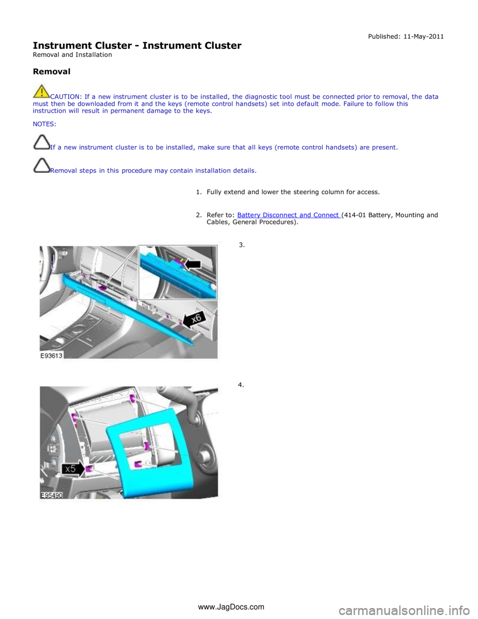
1. Fully extend and lower the steering column for access.
2. Refer to: Battery Disconnect and Connect (414-01 Battery, Mounting and Cables, General Procedures).
3.
4. www.JagDocs.com
Page 1832 of 3039
Warning Devices - Blindspot Monitoring System - Overview
Description and Operation
OVERVIEW Published: 11-May-2011
Eliminating blind spots is a major element in vehicle body design, but because of the structural requirements of B, C and D
posts, blind spots cannot be entirely eliminated. Statistics show that some accidents are directly attributable to drivers moving
across into the path of overtaking vehicles that have not been seen in conventional mirrors. New mirror designs have improved
the situation, but by remotely covering areas that cannot be seen either directly or by the vehicle mirrors, have led to the
introduction of a radar-based blind spot monitoring system.
The blind spot monitoring system comprises:
LH (left-hand) Blind spot monitoring sensor
RH (right-hand) Blind spot monitoring sensor
LH door mirror RH door mirror
The system uses two radar modules operating at a frequency of 24 GHz and each combining the radar face and electronic
module in a single unit. The modules are located behind the rear bumper surface, symmetrically, one on each side of the car
behind the rear wheels. They are side facing and inclined rearwards at an angle of 16 degrees, which is dictated by the shape
at the rear of the vehicle. Each module is calibrated to detect a vehicle in the driver’s blind spot. Once a vehicle is detected
the module illuminates an amber warning ‘alert icon’ LED (light emitting diode) in the relevant exterior door mirror. If there is a
fault or blockage with the blind spot monitoring system an amber warning indicator dot LED is displayed in the exterior mirror and the message ‘blind spot monitoring not available’ is displayed in the instrument cluster message center.
When the system initiates, it performs a self-check, during which the warning icons in the mirrors illuminate alternately for a
short period of time. Each module does a left/right determination check when the ignition is switched on. Each mirror has a
different circuit configuration so that the modules can determine which mirror they are connected to. If a module detects the
wrong mirror it will go into a fault condition.
The blind spot monitoring modules receive vehicle speed on the medium speed CAN (controller area network) and are inactive
until the vehicle reaches 16kph (10mph). Each blind spot monitor module emits a radar field greater than the blind spot area.
Each Blind Spot Monitor module emits a radar field greater than the blind spot area. The actual blind spot area is calibrated
into the module during its manufacture.
CAUTION: The blind spot monitoring system is designed as a driver aid not a safety device. The driver should always
exercise due care and attention whilst driving. www.JagDocs.com
Page 1944 of 3039

12 Portable audio interface console (Optional) 13 Portable audio module (Optional) 14 Steering wheel remote audio controls
Page 1947 of 3039
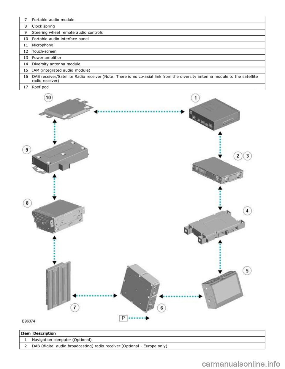
8 Clock spring 9 Steering wheel remote audio controls 10 Portable audio interface panel 11 Microphone 12 Touch-screen 13 Power amplifier 14 Diversity antenna module 15 IAM (integrated audio module) 16 DAB receiver/Satellite Radio receiver (Note: There is no co-axial link from the diversity antenna module to the satellite radio receiver) 17 Roof pod
Item Description 1 Navigation computer (Optional) 2 DAB (digital audio broadcasting) radio receiver (Optional - Europe only)
Page 1974 of 3039
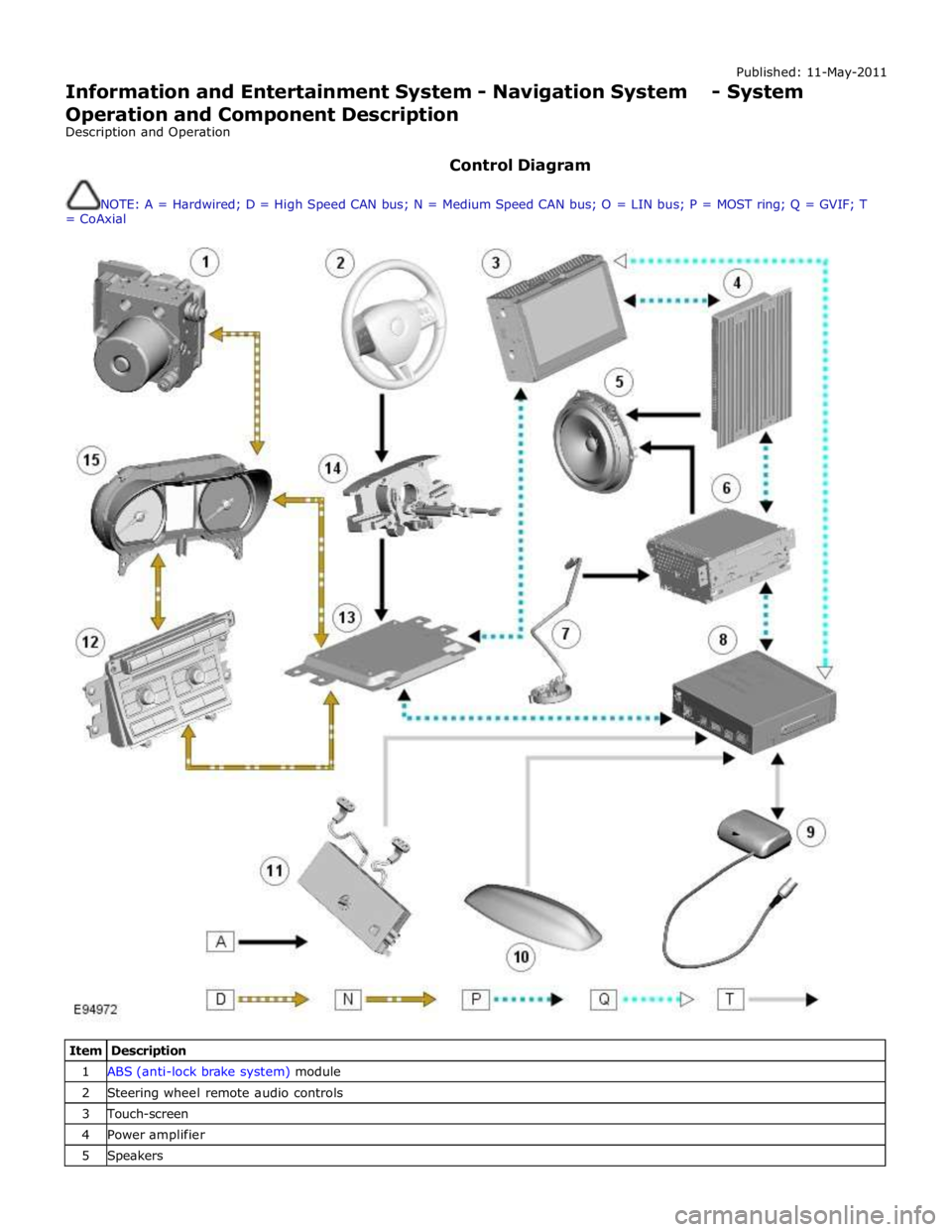
Published: 11-May-2011
Information and Entertainment System - Navigation System - System
Operation and Component Description
Description and Operation
Control Diagram
NOTE: A = Hardwired; D = High Speed CAN bus; N = Medium Speed CAN bus; O = LIN bus; P = MOST ring; Q = GVIF; T
= CoAxial
Item Description 1 ABS (anti-lock brake system) module 2 Steering wheel remote audio controls 3 Touch-screen 4 Power amplifier 5 Speakers