2010 JAGUAR XFR rear view mirror
[x] Cancel search: rear view mirrorPage 2040 of 3039
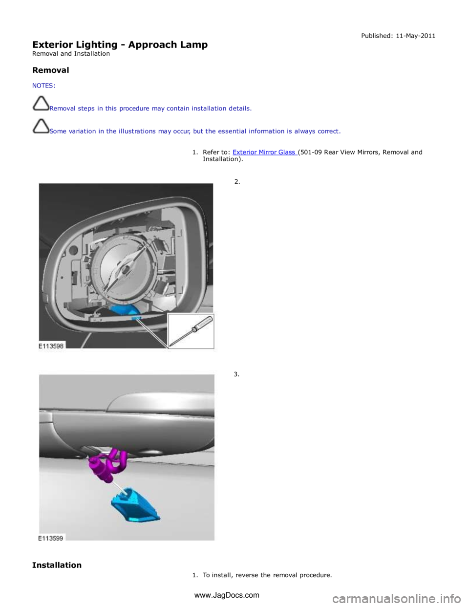
Exterior Lighting - Approach Lamp
Removal and Installation
Removal
NOTES:
Removal steps in this procedure may contain installation details.
Some variation in the illustrations may occur, but the essential information is always correct. Published: 11-May-2011
1. Refer to: Exterior Mirror Glass (501-09 Rear View Mirrors, Removal and Installation).
2.
3.
Installation
1. To install, reverse the removal procedure. www.JagDocs.com
Page 2053 of 3039
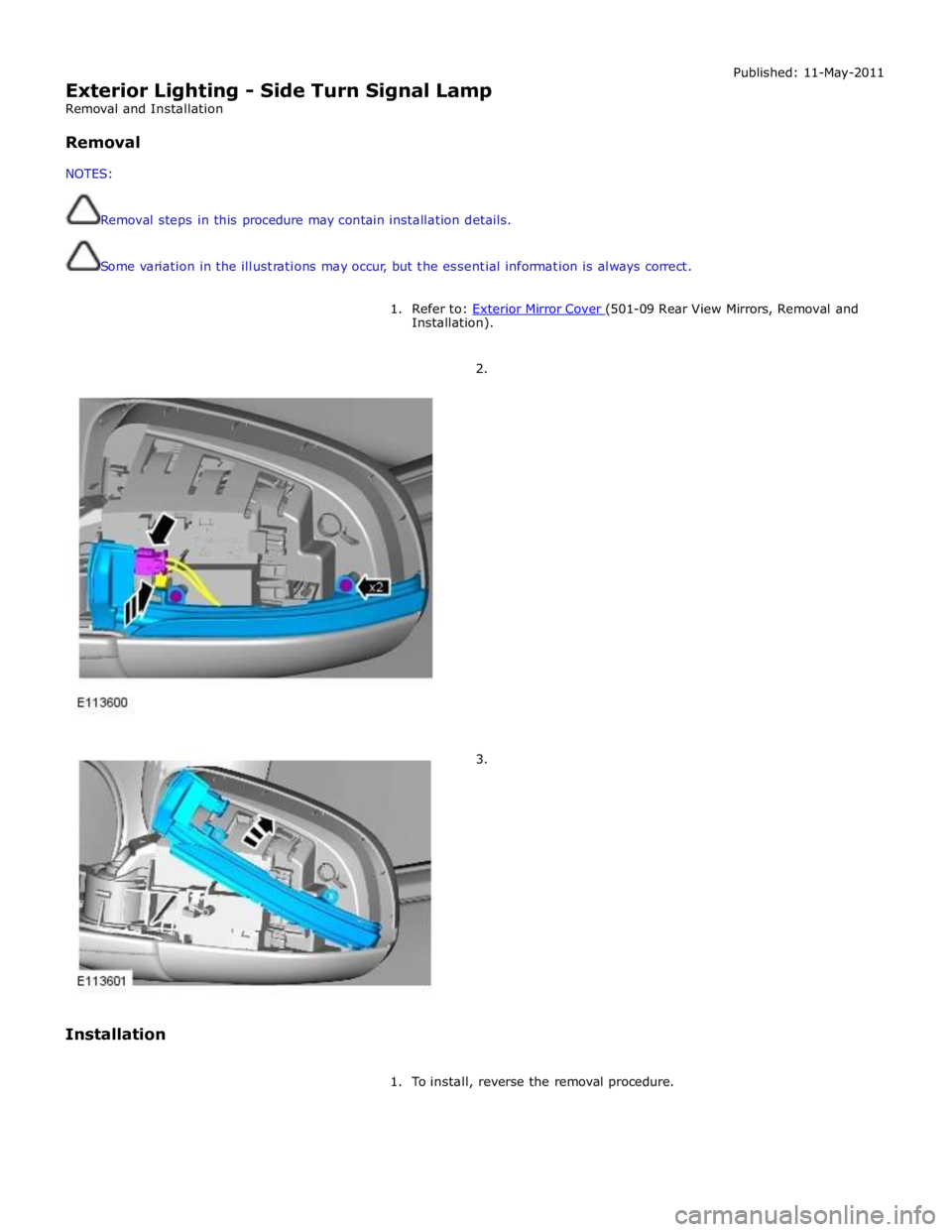
Exterior Lighting - Side Turn Signal Lamp
Removal and Installation
Removal
NOTES:
Removal steps in this procedure may contain installation details.
Some variation in the illustrations may occur, but the essential information is always correct. Published: 11-May-2011
1. Refer to: Exterior Mirror Cover (501-09 Rear View Mirrors, Removal and Installation).
2.
3.
Installation
1. To install, reverse the removal procedure.
Page 2055 of 3039
Interior Lighting - Interior Lighting - Overview
Description and Operation
OVERVIEW Published: 11-May-2011
Interior lighting is provided to enable the safe entry and departure from the vehicle for the driver and passengers in low
ambient light conditions, without any manual switching of the lights.
NOTE: The term interior lamps also includes the door mirror approach lamps.
The interior lamps are controlled by the CJB (central junction box) and the RJB (rear junction box) and have 2 modes of
operation: manual and automatic. The front interior lamps in the front overhead console are operated using the 'JaguarSense'
system. The system uses capacitive proximity sensor technology for the switch operation which is integral with the overhead
console. The rear overhead console interior lamps have conventional switches.
In the manual mode the interior lamps can be switched on and off with the JaguarSense system. Positioning your hand
adjacent to each lamp in the front overhead console will switch interior lamps on or off and completely disable the interior
lamp system. In the automatic mode the interior lamp functionality is controlled by the CJB and the RJB and reacts to the vehicle being locked or unlocked and opening the vehicle doors.
In manual mode the interior lamps can be operated by placing your finger(s) close to, or touch, the surface of the appropriate
lamp. The courtesy light and map reading lamps can be operated manually by the 'JaguarSense' system. When in automatic
mode, the courtesy lamp functionality is also controlled by the CJB and the RJB and reacts to the vehicle being locked or unlocked and opening the vehicle doors. To deactivate or activate automatic illumination, touch the front courtesy lamp for
approximately 2 seconds
The driver's and passenger door approach lamps are controlled by the driver's door module and the passenger door module
respectively and operate with the automatic mode. The door modules receive a power supply from the RJB and receive information to illuminate the approach lamps on the medium speed CAN (controller area network) bus from the RJB and the CJB. www.JagDocs.com
Page 2091 of 3039

DTC Description Possible Cause Action B1D2711
Heater Coolant
Pump
Heater coolant pump control
circuit - short to ground Carry out any pinpoint tests associated with this DTC
using the manufacturer approved diagnostic system.
Refer to the electrical circuit diagrams and check heater
coolant pump control circuit for short to ground B1D2713
Heater Coolant
Pump
Heater coolant pump control
circuit - open circuit Carry out any pinpoint tests associated with this DTC
using the manufacturer approved diagnostic system.
Refer to the electrical circuit diagrams and check heater
coolant pump control circuit for open circuit B1D9796 Tilt Sensor
Component internal failure Suspect the battery backed sounder, check and install a
new battery backed sounder as required P057112
Brake Switch A
Circuit
Footbrake switch circuit - short
to power Refer to the electrical circuit diagrams and check
footbrake switch circuit for short to power P080111
Reverse Inhibit
Control Circuit
Electrochromic rear view mirror,
reverse inhibit circuit - short to
ground Carry out any pinpoint tests associated with this DTC
using the manufacturer approved diagnostic system.
Refer to the electrical circuit diagrams and check
electrochromic rear view mirror, reverse inhibit circuit for
short to ground P080112
Reverse Inhibit
Control Circuit
Electrochromic rear view mirror,
reverse inhibit circuit - short to
power Refer to the electrical circuit diagrams and check
electrochromic rear view mirror, reverse inhibit circuit for
short to power P080113
Reverse Inhibit
Control Circuit
Electrochromic rear view mirror,
reverse inhibit circuit - open
circuit Refer to the electrical circuit diagrams and check
electrochromic rear view mirror, reverse inhibit circuit for
open circuit P085013
Park/Neutral Switch
Input Circuit
Park/Neutral signal circuit -
open circuit Refer to the electrical circuit diagrams and check
Park/Neutral signal circuit for open circuit P162413 Anti-theft System
RJB anti-theft signal circuit -
open circuit Refer to the electrical circuit diagrams and check RJB
anti-theft signal circuit for open circuit P254F13
Engine Hood Switch
Circuit/Open
Hood ajar switch signal circuit -
open circuit Refer to the electrical circuit diagrams and check hood
ajar switch signal circuit for open circuit U001988
Low Speed CAN
Communication Bus
Bus OFF Carry out any pinpoint tests associated with this DTC
using the manufacturer approved diagnostic system. U014200
Lost
Communication
With Body Control
Module "B"
No sub type information Carry out any pinpoint tests associated with this DTC
using the manufacturer approved diagnostic system. U015500
Lost
Communication
With Instrument
Panel Cluster (IPC)
Control Module
No sub type information Carry out any pinpoint tests associated with this DTC
using the manufacturer approved diagnostic system. U015600
Lost
Communication
With Information
Center "A"
No sub type information Carry out any pinpoint tests associated with this DTC
using the manufacturer approved diagnostic system. U016400
Lost
Communication
With HVAC Control
Module
No sub type information Carry out any pinpoint tests associated with this DTC
using the manufacturer approved diagnostic system. U016800
Lost
Communication
With Vehicle
Security Control
Module
No sub type information Check power and ground supplies to vehicle security
module U019900
Lost
Communication
With "Door Control
Module A"
No sub type information Carry out any pinpoint tests associated with this DTC
using the manufacturer approved diagnostic system. U020000
Lost
Communication
With "Door Control
Module B"
No sub type information Carry out any pinpoint tests associated with this DTC
using the manufacturer approved diagnostic system.
Page 2172 of 3039
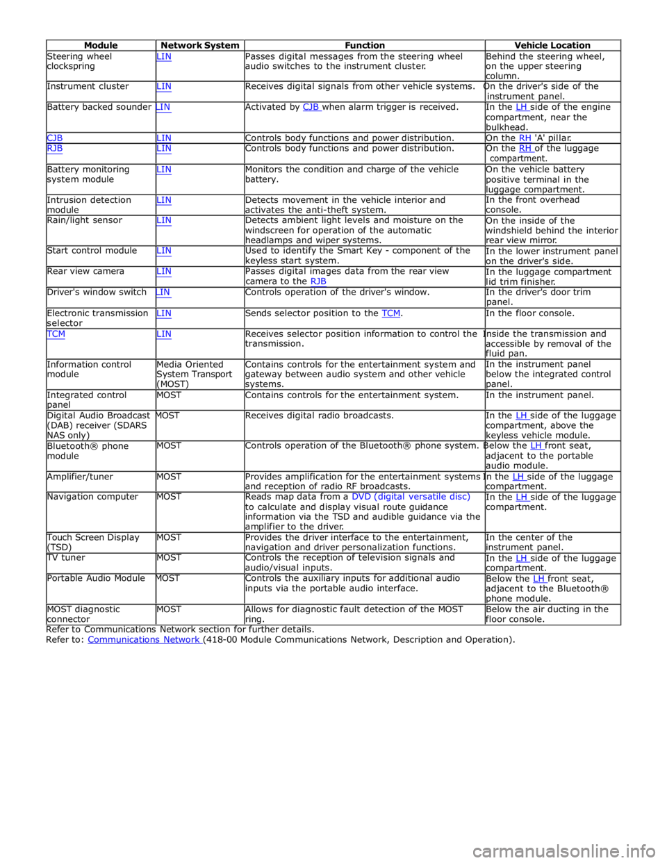
Module Network System Function Vehicle Location
Steering wheel
clockspring LIN Passes digital messages from the steering wheel
audio switches to the instrument cluster. Behind the steering wheel,
on the upper steering
column.
Instrument cluster LIN Receives digital signals from other vehicle systems. On the driver's side of the
instrument panel.
Battery backed sounder LIN Activated by CJB when alarm trigger is received. In the LH side of the engine compartment, near the
bulkhead.
CJB LIN Controls body functions and power distribution. On the RH 'A' pillar.
RJB LIN Controls body functions and power distribution. On the RH of the luggage compartment.
Battery monitoring
system module
Intrusion detection
module LIN Monitors the condition and charge of the vehicle
battery.
LIN Detects movement in the vehicle interior and
activates the anti-theft system. On the vehicle battery
positive terminal in the
luggage compartment.
In the front overhead
console.
Rain/light sensor LIN Detects ambient light levels and moisture on the
windscreen for operation of the automatic
headlamps and wiper systems.
Start control module LIN Used to identify the Smart Key - component of the
keyless start system.
Rear view camera LIN Passes digital images data from the rear view
camera to the RJB On the inside of the
windshield behind the interior
rear view mirror.
In the lower instrument panel
on the driver's side.
In the luggage compartment
lid trim finisher.
Driver's window switch LIN Controls operation of the driver's window. In the driver's door trim
panel.
Electronic transmission
selector LIN Sends selector position to the TCM. In the floor console. TCM LIN Receives selector position information to control the Inside the transmission and
Information control
module
Media Oriented
System Transport
(MOST) transmission.
Contains controls for the entertainment system and
gateway between audio system and other vehicle
systems. accessible by removal of the
fluid pan.
In the instrument panel
below the integrated control
panel.
Integrated control
panel MOST Contains controls for the entertainment system. In the instrument panel.
Digital Audio Broadcast MOST Receives digital radio broadcasts. In the LH side of the luggage (DAB) receiver (SDARS
NAS only)
Bluetooth® phone
module compartment, above the
keyless vehicle module.
MOST Controls operation of the Bluetooth® phone system. Below the LH front seat, adjacent to the portable
audio module.
Amplifier/tuner MOST Provides amplification for the entertainment systems In the LH side of the luggage and reception of radio RF broadcasts.
Navigation computer MOST Reads map data from a DVD (digital versatile disc)
to calculate and display visual route guidance
information via the TSD and audible guidance via the
amplifier to the driver. compartment.
In the LH side of the luggage compartment.
Touch Screen Display
(TSD) MOST Provides the driver interface to the entertainment,
navigation and driver personalization functions. In the center of the
instrument panel.
TV tuner MOST Controls the reception of television signals and
audio/visual inputs.
Portable Audio Module MOST Controls the auxiliary inputs for additional audio
inputs via the portable audio interface. In the LH side of the luggage compartment.
Below the LH front seat, adjacent to the Bluetooth®
phone module.
MOST diagnostic
connector MOST Allows for diagnostic fault detection of the MOST
ring. Below the air ducting in the
floor console.
Refer to Communications Network section for further details.
Refer to: Communications Network (418-00 Module Communications Network, Description and Operation).
Page 2212 of 3039
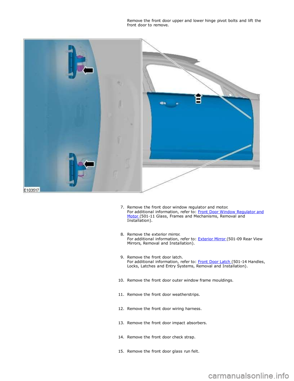
Motor (501-11 Glass, Frames and Mechanisms, Removal and Installation).
8. Remove the exterior mirror.
For additional information, refer to: Exterior Mirror (501-09 Rear View Mirrors, Removal and Installation).
9. Remove the front door latch.
For additional information, refer to: Front Door Latch (501-14 Handles, Locks, Latches and Entry Systems, Removal and Installation).
10. Remove the front door outer window frame mouldings.
11. Remove the front door weatherstrips.
12. Remove the front door wiring harness.
13. Remove the front door impact absorbers.
14. Remove the front door check strap.
15. Remove the front door glass run felt.
Page 2253 of 3039
Interior Trim and Ornamentation - Headliner
Removal and Installation
Removal
NOTE: Removal steps in this procedure may contain installation details. Published: 11-May-2011
1. Refer to: Battery Disconnect and Connect (414-01 Battery, Mounting and Cables, General Procedures).
2. Refer to: Interior Rear View Mirror (501-09 Rear View Mirrors, Removal and Installation).
3. Refer to: Overhead Console (501-12 Instrument Panel and Console, Removal and Installation).
4.
Remove both sun visors.
Refer to: Sun Visor (501-05 Interior Trim and Ornamentation, Removal and Installation).
5.
Remove both A-pillar trim panels.
Refer to: A-Pillar Trim Panel (501-05 Interior Trim and Ornamentation, Removal and Installation).
6.
Remove both B-pillar upper trim panels.
Refer to: B-Pillar Upper Trim Panel (501-05 Interior Trim and Ornamentation, Removal and Installation).
7.
Remove both C-pillar trim panels.
Refer to: C-Pillar Trim Panel (501-05 Interior Trim and Ornamentation, Removal and Installation).
8.
Remove both front seats.
Refer to: Front Seat (501-10 Seating, Removal and Installation).
9. Refer to: Rear Seat Cushion (501-10 Seating, Removal and Installation).
Page 2291 of 3039
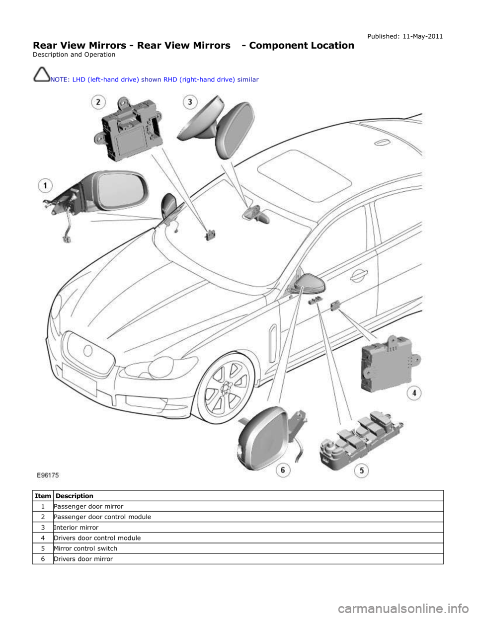
Rear View Mirrors - Rear View Mirrors - Component Location
Description and Operation
NOTE: LHD (left-hand drive) shown RHD (right-hand drive) similar Published: 11-May-2011
Item Description 1 Passenger door mirror 2 Passenger door control module 3 Interior mirror 4 Drivers door control module 5 Mirror control switch 6 Drivers door mirror