2010 JAGUAR XFR rear entertainment
[x] Cancel search: rear entertainmentPage 1847 of 3039
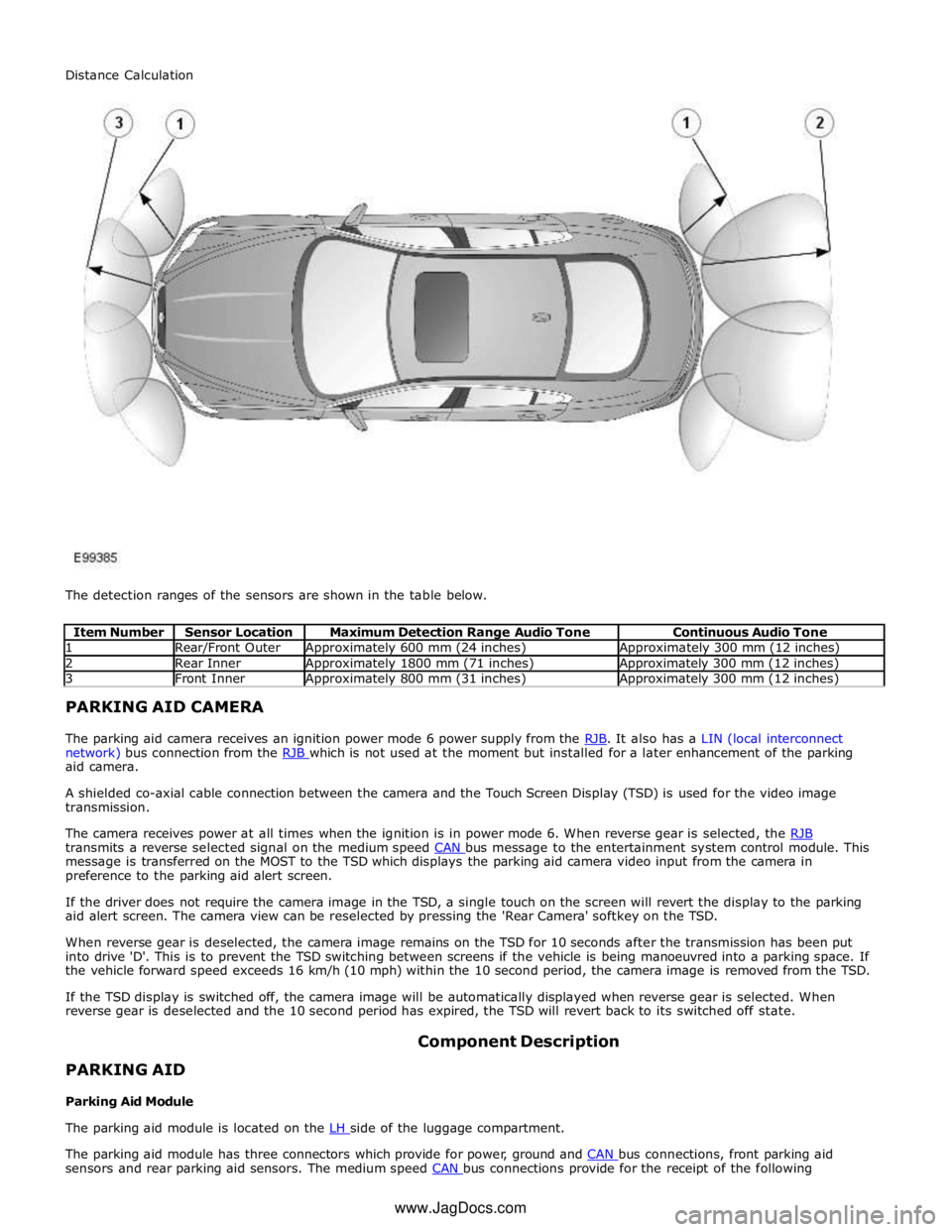
1 Rear/Front Outer Approximately 600 mm (24 inches) Approximately 300 mm (12 inches) 2 Rear Inner Approximately 1800 mm (71 inches) Approximately 300 mm (12 inches) 3 Front Inner Approximately 800 mm (31 inches) Approximately 300 mm (12 inches) PARKING AID CAMERA
The parking aid camera receives an ignition power mode 6 power supply from the RJB. It also has a LIN (local interconnect network) bus connection from the RJB which is not used at the moment but installed for a later enhancement of the parking aid camera.
A shielded co-axial cable connection between the camera and the Touch Screen Display (TSD) is used for the video image
transmission.
The camera receives power at all times when the ignition is in power mode 6. When reverse gear is selected, the RJB transmits a reverse selected signal on the medium speed CAN bus message to the entertainment system control module. This message is transferred on the MOST to the TSD which displays the parking aid camera video input from the camera in
preference to the parking aid alert screen.
If the driver does not require the camera image in the TSD, a single touch on the screen will revert the display to the parking
aid alert screen. The camera view can be reselected by pressing the 'Rear Camera' softkey on the TSD.
When reverse gear is deselected, the camera image remains on the TSD for 10 seconds after the transmission has been put
into drive 'D'. This is to prevent the TSD switching between screens if the vehicle is being manoeuvred into a parking space. If
the vehicle forward speed exceeds 16 km/h (10 mph) within the 10 second period, the camera image is removed from the TSD.
If the TSD display is switched off, the camera image will be automatically displayed when reverse gear is selected. When
reverse gear is deselected and the 10 second period has expired, the TSD will revert back to its switched off state.
PARKING AID
Parking Aid Module Component Description
The parking aid module is located on the LH side of the luggage compartment.
The parking aid module has three connectors which provide for power, ground and CAN bus connections, front parking aid sensors and rear parking aid sensors. The medium speed CAN bus connections provide for the receipt of the following Distance Calculation
www.JagDocs.com
Page 1849 of 3039
PARKING AID CAMERA
The parking aid camera receives an ignition power mode 6 power supply from the RJB. It also has a LIN bus connection with the RJB, which is used as a gateway. A shielded co-axial cable connection between the camera and the TSD is used for the video image transmission.
The camera receives power at all times when the ignition is in power mode 6. When reverse gear is selected, the RJB transmits a reverse selected message on the medium speed CAN bus. The information and entertainment module transfers the message on the MOST ring to the TSD, which displays the video input from the parking aid camera in preference to the parking
aid alert screen.
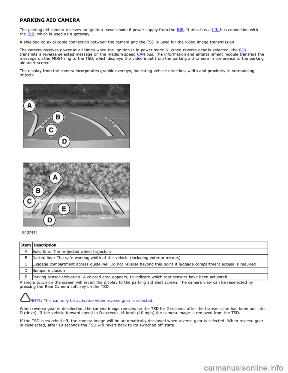
The display from the camera incorporates graphic overlays, indicating vehicle direction, width and proximity to surrounding
objects.
Item Description A Solid line: The projected wheel trajectory B Dotted line: The safe working width of the vehicle (including exterior mirrors) C Luggage compartment access guideline: Do not reverse beyond this point if luggage compartment access is required D Bumper inclusion E Parking sensor activation: A colored area appears, to indicate which rear sensors have been activated A single touch on the screen will revert the display to the parking aid alert screen. The camera view can be reselected by
pressing the Rear Camera soft key on the TSD.
NOTE: This can only be activated when reverse gear is selected.
When reverse gear is deselected, the camera image remains on the TSD for 2 seconds after the transmission has been put into
D (drive). If the vehicle forward speed in D exceeds 16 km/h (10 mph) the camera image is removed from the TSD.
If the TSD is switched off, the camera image will be automatically displayed when reverse gear is selected. When reverse gear
is deselected, after 10 seconds the TSD will revert back to its switched off state.
Page 1873 of 3039

Published: 02-Apr-2014
Battery and Charging System - General Information - Battery Report Form – In Service Batteries Only
Description and Operation
NOTE: Fields marked with * are mandatory and must be completed.
General Information *Vehicle Identification Number (VIN):
Vehicle
Model: Engine type: *Mileage:
*Repair
Date: - Customer Questions *1: What is the customer’s reason for dealer visit? (tick symptoms as appropriate) Non crank
Crank but non
start Warning message Other: *2: How long was the vehicle left prior to issue. * *3: How was the car left (Locked/unlocked) * *4: How did you access to the vehicle Key fob Manual key Handle pull *5: Has the vehicle required assistance for battery issues previously? Yes No *6: Is the vehicle used? (tick symptoms as appropriate) Daily
Every other day Weekly
Less than weekly *7: Average journey length * *8: How many starts do you typically do in a day * *9: Did the customer see any instrument pack warnings prior to the
issue? * *10: Have any of the features been used
without the engine running in the last 3 days (if fitted?) Radio
Power point
accessory CD DVD USB or IPOD
connection TV
Rear seat
entertainment 11: Customer comments:- Please add any additional comments that
are relevant. * Diagnostics (Battery Testing) - - - - 1: Loose battery clamps Yes * No * 2: Loose hold down clamps Yes * No * 3: Corroded terminal posts Yes * No * 4: Physical damage/leaks Yes No * 5: Low electrolyte (Flooded batteries only) Yes * No * 6: Battery Date Code * 7: FEAD belt tension OK * Not OK * 8: Quiescent Drain mA * 9: Vent tube correctly installed Yes * No * 10: Number of Times Battery Charged: * 10: Vent tube correctly installed Yes No 11: Remove the Surface (414-00 battery care requirements) Yes * No * 12: Battery voltage * 13: Midtronics test code before charging (EXP-1080) * 13a: If Midtronics indicates that the battery needs re-charging, charge
the battery following instructions on the recommended battery charger * 13b: Midtronics test code after charge * 13c: Midtronics test code result after charge * 13d: If "good and re-charge" charge the battery following instructions
on the recommended battery charger * 13e: If "charge and re-test" for both before and after the charge
renew the battery * 13f: Only renew the battery if "renew battery", "bad cell" or charge
and re-test has been displayed twice. * Technician Comments:- Please add any additional comments that are relevant. * * * * *
Page 1946 of 3039
Published: 11-May-2011
Information and Entertainment System - Audio System - System Operation
and Component Description
Description and Operation
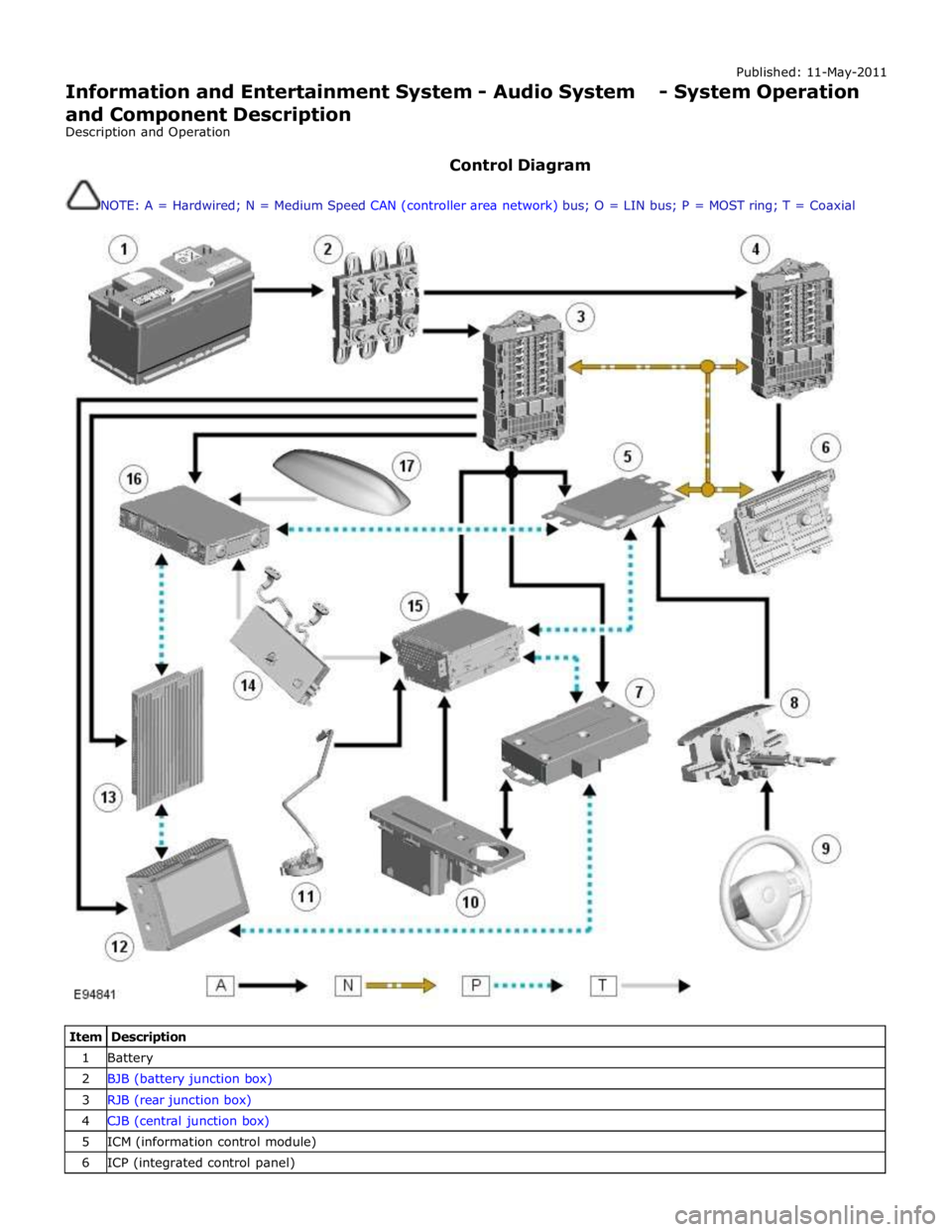
Control Diagram
NOTE: A = Hardwired; N = Medium Speed CAN (controller area network) bus; O = LIN bus; P = MOST ring; T = Coaxial
Item Description 1 Battery 2 BJB (battery junction box) 3 RJB (rear junction box) 4 CJB (central junction box) 5 ICM (information control module) 6 ICP (integrated control panel)
Page 1958 of 3039
The digital radio format adopted for NAS vehicles is satellite radio. Satellite service providers transmit a signal from their
up-link facility (which is the original point of transmission of data, voice or other information through an antenna system) to a
satellite where the signal is then down linked to both the terrestrial repeater network and the individual satellite car radios.
The radio switches between the satellite signal and the repeater network signal depending on the strength of the signal at any
given time.
The Sirius satellite system comprises:
Satellites
Ground repeaters
Up-link ground stations
Radio receiver systems
The Sirius satellite radio system uses three satellites on an inclined elliptical orbit. This ensures that each satellite spends
approximately 16 hours a day over the continent of the USA, with at least one satellite over the country at any one time.
The satellites beam their signals down to the ground where the signal is picked up by receivers or is transmitted to repeater
stations to cover built up areas where the signal is obscured. The satellite service comprises over 100 channels of digital
entertainment which is provided by subscription requiring a monthly payment.
Operation of the satellite radio system is the same as the radio operations with selections made through the Touch-screen and
ICP to access and navigate the system functions.
The satellite radio receiver is a dedicated tuner which is controlled by the ICM on the MOST ring. The receiver filters the
signals from the satellite radio antenna. Information is transmitted on the MOST ring and processed by the ICM. The processed
information is sent out to the power amplifier or IAM (with internal amplifier) and broadcast through the speaker system.
No configuration procedure is required if the satellite radio receiver is replaced. Calibration of the satellite radio receiver using
the Jaguar approved diagnostic equipment enables updates to be downloaded as new technology becomes available or any
fault concerns require software updates.
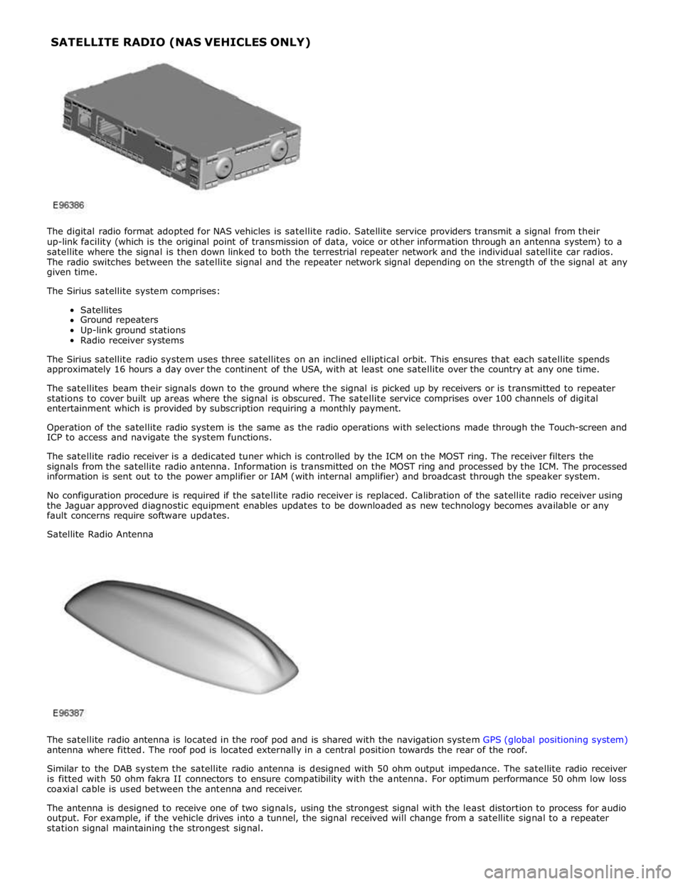
Satellite Radio Antenna
The satellite radio antenna is located in the roof pod and is shared with the navigation system GPS (global positioning system)
antenna where fitted. The roof pod is located externally in a central position towards the rear of the roof.
Similar to the DAB system the satellite radio antenna is designed with 50 ohm output impedance. The satellite radio receiver
is fitted with 50 ohm fakra II connectors to ensure compatibility with the antenna. For optimum performance 50 ohm low loss
coaxial cable is used between the antenna and receiver.
The antenna is designed to receive one of two signals, using the strongest signal with the least distortion to process for audio
output. For example, if the vehicle drives into a tunnel, the signal received will change from a satellite signal to a repeater
station signal maintaining the strongest signal. SATELLITE RADIO (NAS VEHICLES ONLY)
Page 1959 of 3039
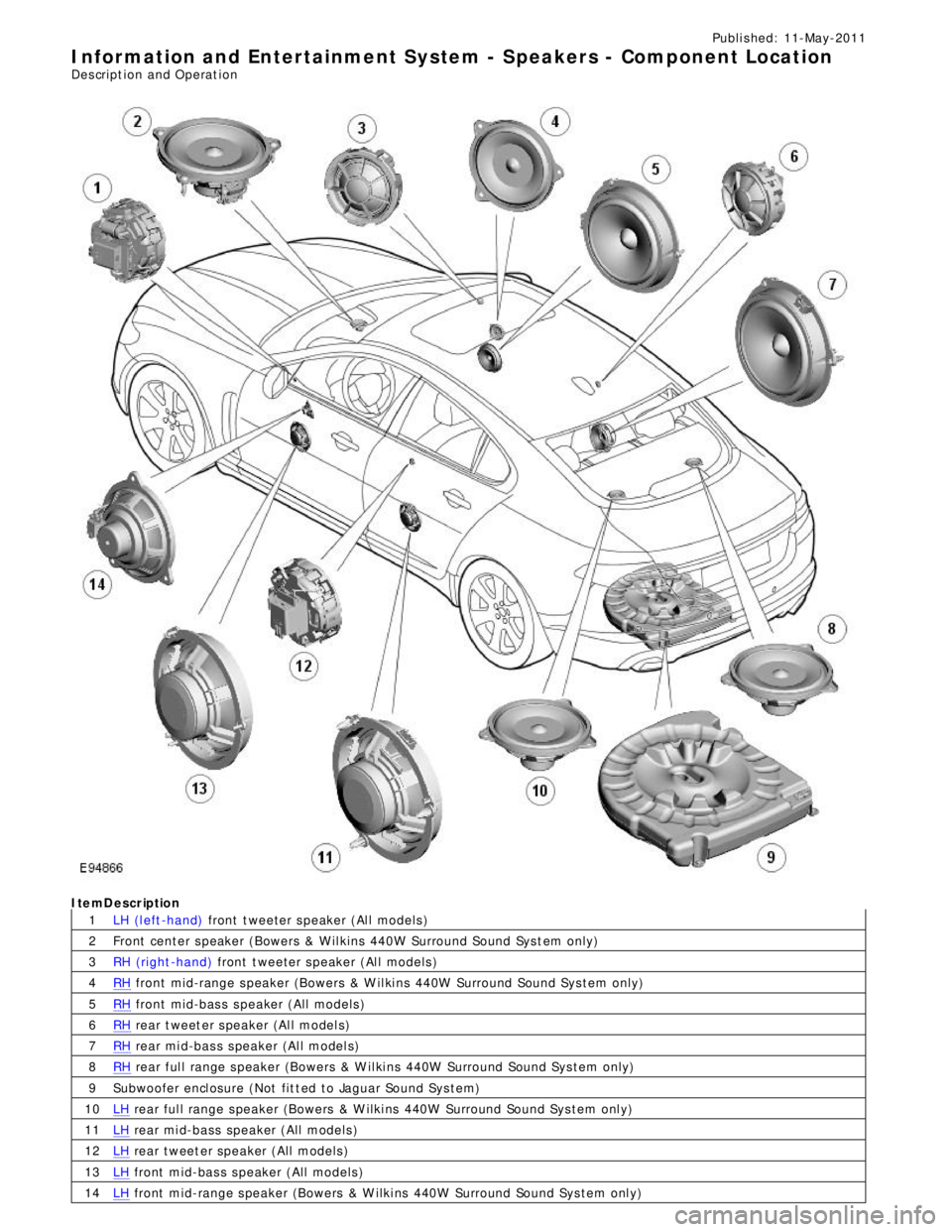
1
2
3
4
5
6
7
8
9
10
11
12
13
14Publi s hed: 11-May-2011
Information and Entertainment System - Speakers - Component Location
Des cript ion and Operat ionItemDescription
LH (l eft -hand) front t weeter s peaker (Al l models )
Front center s peaker (Bowers & W il kins 440W Surround Sound Sys t em only)
RH (right -hand) front t weeter s peaker (Al l models )RH front mid-range s peaker (Bowers & W il ki ns 440W Surround Sound Sys tem only)RH front mid-bas s s peaker (All models )RH rear t weet er s peaker (Al l model s)RH rear mi d-bas s s peaker (Al l model s)RH rear ful l range s peaker (Bowers & W il ki ns 440W Surround Sound Sys tem only)
Subwoofer encl osure (Not fit t ed to Jaguar Sound Sys tem)LH rear ful l range s peaker (Bowers & W ilki ns 440W Surround Sound Sys tem onl y)LH rear mi d-bass speaker (All models )LH rear tweet er speaker (All models )LH front mid-bas s s peaker (All models )LH front mid-range s peaker (Bowers & W ilki ns 440W Surround Sound Sys tem onl y)
Page 1960 of 3039

Publi s hed: 11-May-2011
Information and Entertainment System - Speakers - Overview
Des cript ion and Operat ion
Overview
The vehi cl e has t hree l evels of audio s ys t em availabl e:
Jaguar Sound Sys temJaguar Premi um Sound Syst emBowers & W i lkins Surround Sound Sys temThe Jaguar Sound Sys tem has 8 s peakers, compri s ing an i dent ical mid-bas s and t weeter combinati on in each door. Al l
s peaker domes in this sys tem are of st andard t ext il e cons t ructi on. The s peakers are driven direct ly by the IAM (i nt egrat ed
audi o module) i nternal ampli fi er.
The Jaguar 320W Premium Sound Sys tem has 9 s peakers including mid-bas s and t weet ers in t he doors , addi ng a
s ub-woofer in the spare wheel wel l. The s peakers are driven by an Al pi ne AUD 8 ampli fier l ocat ed in t he LH (left-hand)
s ide of t he luggage compartment .
The Bowers & W i lkins 440W Surround Sound Syst em us es an Al pi ne AUD 12 amplifier, a Dolby Pro-Logi c 2 7.1 Surround
Sound Sys t em and has 14 s peakers. This layout adds a mid-range s peaker to each front door whi le ret ai ning a mid-bas s
and t weet er in each rear door. It als o adds an i ns t rument panel center s peaker, 2 s urround-effect speakers i n t he rear
parcel shelf, and has the luggage compart ment-mounted sub-woofer as the Jaguar 320W Premi um Sound Sys t em. The
s peakers are driven by an AUD 12 power ampl ifier located i n t he luggage compartment .
The main s peakers on the Jaguar 320W Premium Sound Sys t em and t he Bowers & W i lkins 440W Surround Sound Syst em
are identi fied by the bright yellow Kevl ar cons truct ed domes which are vis ibl e through the s peaker grill es. The t weeter
s peaker domes are an al uminum cons truct ion. The s ub-woofer s peakers are a text ile dome cons t ructi on.
www.JagDocs.com
Page 1961 of 3039
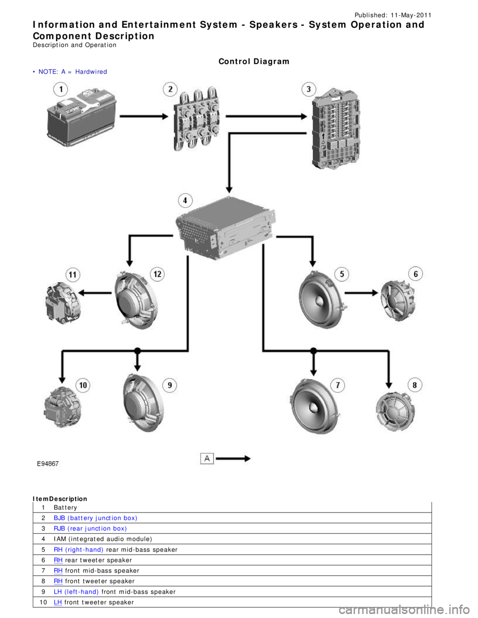
1
2
3
4
5
6
7
8
9
10Publi s hed: 11-May-2011
Information and Entertainment System - Speakers - System Operation and
Component Description
Des cript ion and Operat ion
Control Diagram
• NOTE: A = Hardwi red
CONTROL DIAGRAM - JAGUAR SOUND SY STEMItemDescription
Bat tery
BJB (batt ery junct ion box)
RJB (rear junct ion box)
IAM (i nt egrat ed audi o module)
RH (right -hand) rear mid-bass speakerRH rear t weet er s peakerRH front mid-bas s s peakerRH front tweet er s peaker
LH (l eft -hand) front mid-bas s s peakerLH front t weeter s peaker