2010 JAGUAR XFR oil filler
[x] Cancel search: oil fillerPage 878 of 3039

Published: 11-May-2011
Engine - V8 S/C 5.0L Petrol - Engine Oil Vacuum Draining and Filling
General Procedures
Special Tool(s)
303-1484
Vacuum Pump, Oil Drain
303-1484-01
Adapter for 303-1484
Draining
WARNING: The spilling of hot engine oil is unavoidable during this procedure, care must be taken to prevent scalding.
CAUTION: Correct installation of the oil filler cap can be obtained by tightening the cap until hard stop.
NOTES:
Make sure that the vehicle is parked on level ground.
Clean the components general area prior to dismantling.
1.
Start the engine and allow to run for 10 minutes, stop the
engine.
2. CAUTION: Allow 10 minutes from turning the engine off
before starting oil extraction.
3. Refer to: Engine Cover - V8 5.0L Petrol/V8 S/C 5.0L Petrol (501-05 Interior Trim and Ornamentation, Removal and Installation).
Page 881 of 3039

Specifications).
Clean any residual engine oil from the oil filler cap area.
4.
5. CAUTION: Make sure that the vehicle has been left for 5 minutes
from filling with oil.
Follow the Steps 7-11 before starting the engine.
6.
Start the engine and allow to run for 10 minutes, stop the
engine.
Check for leaks.
7. CAUTIONS:
Make sure that the selector lever and the gearshift mechanism are
in the park (P) position.
Make sure that the hood is open.
Turn the ignition on. www.JagDocs.com
Page 889 of 3039

17.
18. Torque: 10 Nm
NOTE: Install a new sealing washer.
Torque: 24 Nm
19.
20. Refer to: Battery Disconnect and Connect (414-01 Battery, Mounting and Cables, General Procedures).
CAUTION: Make sure that the vehicle is left for 5 minutes from filling with oil and
that the engine oil level is reading at least minimum (by following Steps 23-27), before
starting the engine.
Fill the engine with oil - for filling values on vehicles without supercharger:
Refer to: Specifications (303-01C Engine - V8 5.0L Petrol, Specifications). Fill the engine with oil - for filling values on vehicles with supercharger:
Refer to: Specifications (303-01D Engine - V8 S/C 5.0L Petrol, Specifications). Clean any residual engine oil from the oil filler cap area.
21.
oil. CAUTION: Make sure that the vehicle has been left for 5 minutes from filling with
Follow the Steps 23-27 before starting the engine.
22.
Start the engine and allow to run for 10 minutes, stop the engine.
Check for leaks.
23. CAUTIONS:
Make sure that the selector lever and the gearshift mechanism are in the park (P)
position.
Make sure that the hood is open.
Turn the ignition on.
Page 896 of 3039

Refer to: Specifications (303-01D Engine - V8 S/C 5.0L Petrol, Specifications).
Clean any residual engine oil from the oil filler cap area.
13. CAUTION: Make sure that the vehicle has been left for 5 minutes
from filling with oil.
Follow the Steps 15-19 before starting the engine.
14.
Start the engine and allow to run for 10 minutes, stop the
engine.
Check for leaks.
15. CAUTIONS:
Make sure that the selector lever and the gearshift mechanism are
in the park (P) position.
Make sure that the hood is open.
Turn the ignition on.
16.
Scroll through the trip menu to access the engine oil
level display. www.JagDocs.com
Page 1080 of 3039

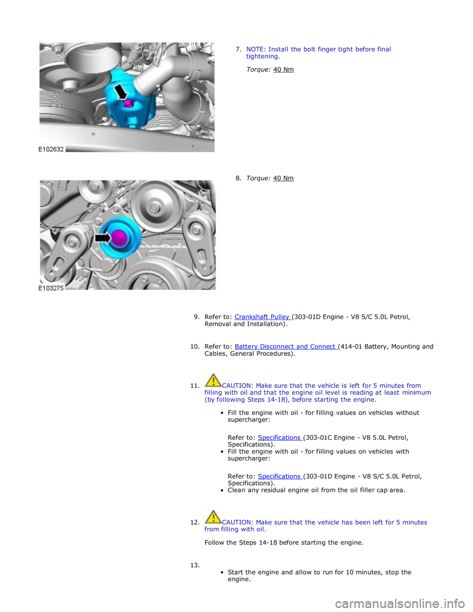
7. NOTE: Install the bolt finger tight before final
tightening.
Torque: 40 Nm
8. Torque: 40 Nm
9. Refer to: Crankshaft Pulley (303-01D Engine - V8 S/C 5.0L Petrol, Removal and Installation).
10. Refer to: Battery Disconnect and Connect (414-01 Battery, Mounting and Cables, General Procedures).
11. CAUTION: Make sure that the vehicle is left for 5 minutes from
filling with oil and that the engine oil level is reading at least minimum
(by following Steps 14-18), before starting the engine.
Fill the engine with oil - for filling values on vehicles without
supercharger:
Refer to: Specifications (303-01C Engine - V8 5.0L Petrol, Specifications).
Fill the engine with oil - for filling values on vehicles with
supercharger:
Refer to: Specifications (303-01D Engine - V8 S/C 5.0L Petrol, Specifications).
Clean any residual engine oil from the oil filler cap area.
12. CAUTION: Make sure that the vehicle has been left for 5 minutes
from filling with oil.
Follow the Steps 14-18 before starting the engine.
13.
Start the engine and allow to run for 10 minutes, stop the
engine.
Page 1435 of 3039

Published: 25-Aug-2011
Automatic Transmission/Transaxle - TDV6 3.0L Diesel /V8 5.0L Petrol/V8 S/C 5.0L Petrol - Diagnostics
Diagnosis and Testing
Principle of Operation
For a detailed description of the automatic transmission/transaxle, refer to the relevant Description and Operation section n
the workshop manual. REFER to: (307-01B Automatic Transmission/Transaxle - TDV6 3.0L Diesel /V8 5.0L Petrol/V8 S/C 5.0L
Petrol)
Transmission Description (Description and Operation), Transmission Description (Description and Operation), Transmission Description (Description and Operation).
Fluid Level and Condition Check
CAUTION: The vehicle should not be driven if the fluid level is low as internal failure can result.
NOTE: The transmission fluid temperature must not be allowed to exceed 50°C (122°F) whilst checking level. Should the
temperature rise above this figure, abort the check and allow the transmission fluid to cool to below 30°C (86°F).
This vehicle is not equipped with a fluid level indicator. An incorrect level may affect the transmission operation and could
result in transmission damage. To correctly check and add fluid to the transmission.
REFER to: Transmission Fluid Level Check (307-01B Automatic Transmission/Transaxle - TDV6 3.0L Diesel /V8 5.0L Petrol/V8 S/C 5.0L Petrol, General Procedures).
High Fluid Level
A fluid level that is too high may cause the fluid to become aerated due to the churning action of the rotating internal parts.
This will cause erratic control pressure, foaming, loss of fluid from the vent tube and possible transmission damage. If an
overfill condition is identified, with the engine at idle ensure the fluid temperature is within the specified range and allow the
excess fluid to drain until a small thread of fluid runs from the filler/level plug hole.
Low Fluid Level
A low fluid level could result in poor transmission engagement, slipping, or damage. This could also indicate a leak in one of
the transmission seals or gaskets.
REFER to: Transmission Fluid Level Check (307-01B Automatic Transmission/Transaxle - TDV6 3.0L Diesel /V8 5.0L Petrol/V8 S/C 5.0L Petrol, General Procedures).
Adding Fluid
CAUTION: The use of any other type of transmission fluid other than that specified can result in transmission damage.
If fluid needs to be added, add fluid in 0.50 liter increments through the fill hole Opening. Do not overfill the fluid. For fluid
type, refer to the General Specification chart in this section.
REFER to: Specifications (307-01B Automatic Transmission/Transaxle - TDV6 3.0L Diesel /V8 5.0L Petrol/V8 S/C 5.0L Petrol, Specifications).
Fluid Condition Check
1. Check the fluid level.
REFER to: Transmission Fluid Level Check (307-01B Automatic Transmission/Transaxle - TDV6 3.0L Diesel /V8 5.0L Petrol/V8 S/C 5.0L Petrol, General Procedures).
2. Observe the color and the odor of the fluid. The color under normal circumstances should be Honey.
3. Allow the fluid to drip onto a facial tissue and examine the stain.
4. If evidence of solid material is found, the transmission fluid pan should be removed for further inspection.
NOTE: In the event of a transmission unit replacement for internal failure, the oil cooler and pipes must also be replaced.
Inspection and Verification
1. Verify the customer concern.
2. Visually inspect for obvious signs of damage and system integrity.
Page 1825 of 3039

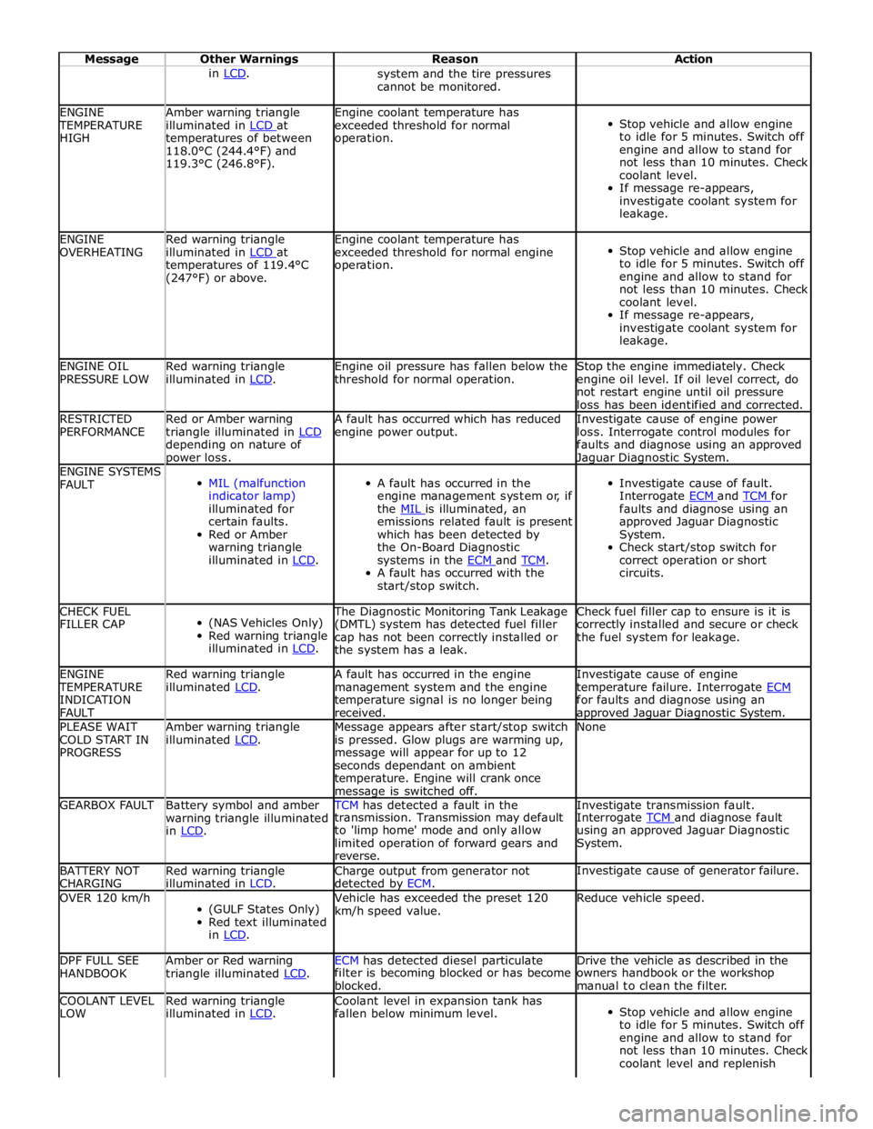
Message Other Warnings Reason Action in LCD. system and the tire pressures
cannot be monitored. ENGINE TEMPERATURE
HIGH Amber warning triangle
illuminated in LCD at temperatures of between
118.0°C (244.4°F) and
119.3°C (246.8°F). Engine coolant temperature has
exceeded threshold for normal
operation.
Stop vehicle and allow engine
to idle for 5 minutes. Switch off
engine and allow to stand for
not less than 10 minutes. Check
coolant level.
If message re-appears,
investigate coolant system for
leakage. ENGINE
OVERHEATING Red warning triangle
illuminated in LCD at temperatures of 119.4°C
(247°F) or above. Engine coolant temperature has
exceeded threshold for normal engine
operation.
Stop vehicle and allow engine
to idle for 5 minutes. Switch off
engine and allow to stand for
not less than 10 minutes. Check
coolant level.
If message re-appears,
investigate coolant system for
leakage. ENGINE OIL
PRESSURE LOW Red warning triangle
illuminated in LCD. Engine oil pressure has fallen below the
threshold for normal operation. Stop the engine immediately. Check
engine oil level. If oil level correct, do
not restart engine until oil pressure
loss has been identified and corrected. RESTRICTED
PERFORMANCE Red or Amber warning
triangle illuminated in LCD depending on nature of power loss. A fault has occurred which has reduced
engine power output. Investigate cause of engine power
loss. Interrogate control modules for
faults and diagnose using an approved Jaguar Diagnostic System. ENGINE SYSTEMS
FAULT
MIL (malfunction
indicator lamp)
illuminated for
certain faults.
Red or Amber
warning triangle
illuminated in LCD.
A fault has occurred in the
engine management system or, if
the MIL is illuminated, an emissions related fault is present
which has been detected by
the On-Board Diagnostic
systems in the ECM and TCM. A fault has occurred with the
start/stop switch.
Investigate cause of fault.
Interrogate ECM and TCM for faults and diagnose using an
approved Jaguar Diagnostic
System.
Check start/stop switch for
correct operation or short
circuits. CHECK FUEL
FILLER CAP
(NAS Vehicles Only)
Red warning triangle
illuminated in LCD. The Diagnostic Monitoring Tank Leakage
(DMTL) system has detected fuel filler
cap has not been correctly installed or
the system has a leak. Check fuel filler cap to ensure is it is
correctly installed and secure or check
the fuel system for leakage. ENGINE TEMPERATURE
INDICATION
FAULT Red warning triangle
illuminated LCD. A fault has occurred in the engine
management system and the engine
temperature signal is no longer being
received. Investigate cause of engine
temperature failure. Interrogate ECM for faults and diagnose using an approved Jaguar Diagnostic System. PLEASE WAIT
COLD START IN
PROGRESS Amber warning triangle
illuminated LCD. Message appears after start/stop switch
is pressed. Glow plugs are warming up,
message will appear for up to 12
seconds dependant on ambient
temperature. Engine will crank once message is switched off. None GEARBOX FAULT
Battery symbol and amber
warning triangle illuminated
in LCD. TCM has detected a fault in the Investigate transmission fault. transmission. Transmission may default
to 'limp home' mode and only allow
limited operation of forward gears and
reverse. Interrogate TCM and diagnose fault using an approved Jaguar Diagnostic
System. BATTERY NOT
CHARGING Red warning triangle
illuminated in LCD. Charge output from generator not
detected by ECM. Investigate cause of generator failure. OVER 120 km/h
(GULF States Only)
Red text illuminated
in LCD. Vehicle has exceeded the preset 120
km/h speed value. Reduce vehicle speed. DPF FULL SEE
HANDBOOK Amber or Red warning
triangle illuminated LCD. ECM has detected diesel particulate Drive the vehicle as described in the filter is becoming blocked or has become
blocked. owners handbook or the workshop
manual to clean the filter. COOLANT LEVEL
LOW Red warning triangle
illuminated in LCD. Coolant level in expansion tank has
fallen below minimum level.
Stop vehicle and allow engine
to idle for 5 minutes. Switch off
engine and allow to stand for
not less than 10 minutes. Check
coolant level and replenish
Page 2099 of 3039

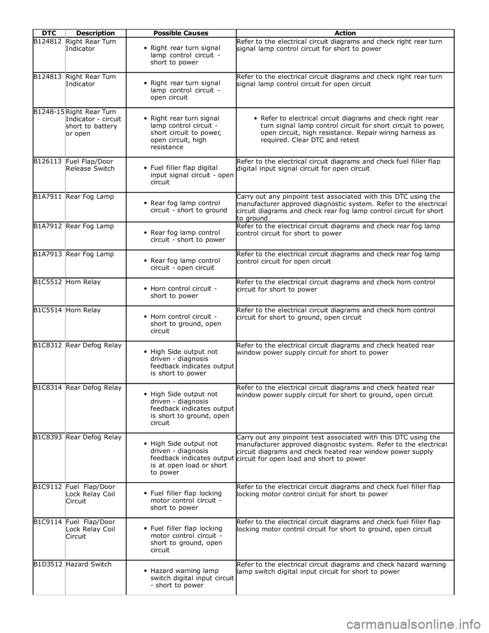
DTC Description Possible Causes Action B124812
Right Rear Turn
Indicator
Right rear turn signal
lamp control circuit -
short to power Refer to the electrical circuit diagrams and check right rear turn
signal lamp control circuit for short to power B124813
Right Rear Turn
Indicator
Right rear turn signal
lamp control circuit -
open circuit Refer to the electrical circuit diagrams and check right rear turn
signal lamp control circuit for open circuit B1248-15
Right Rear Turn
Indicator - circuit
short to battery
or open
Right rear turn signal
lamp control circuit -
short circuit to power,
open circuit, high
resistance
Refer to electrical circuit diagrams and check right rear
turn signal lamp control circuit for short circuit to power,
open circuit, high resistance. Repair wiring harness as
required. Clear DTC and retest B126113
Fuel Flap/Door
Release Switch
Fuel filler flap digital
input signal circuit - open
circuit Refer to the electrical circuit diagrams and check fuel filler flap
digital input signal circuit for open circuit B1A7911 Rear Fog Lamp
Rear fog lamp control
circuit - short to ground Carry out any pinpoint test associated with this DTC using the
manufacturer approved diagnostic system. Refer to the electrical
circuit diagrams and check rear fog lamp control circuit for short
to ground B1A7912 Rear Fog Lamp
Rear fog lamp control
circuit - short to power Refer to the electrical circuit diagrams and check rear fog lamp
control circuit for short to power B1A7913 Rear Fog Lamp
Rear fog lamp control
circuit - open circuit Refer to the electrical circuit diagrams and check rear fog lamp
control circuit for open circuit B1C5512 Horn Relay
Horn control circuit -
short to power Refer to the electrical circuit diagrams and check horn control
circuit for short to power B1C5514 Horn Relay
Horn control circuit -
short to ground, open
circuit Refer to the electrical circuit diagrams and check horn control
circuit for short to ground, open circuit B1C8312 Rear Defog Relay
High Side output not
driven - diagnosis
feedback indicates output
is short to power Refer to the electrical circuit diagrams and check heated rear
window power supply circuit for short to power B1C8314 Rear Defog Relay
High Side output not
driven - diagnosis
feedback indicates output
is short to ground, open
circuit Refer to the electrical circuit diagrams and check heated rear
window power supply circuit for short to ground, open circuit B1C8393 Rear Defog Relay
High Side output not
driven - diagnosis
feedback indicates output
is at open load or short
to power Carry out any pinpoint test associated with this DTC using the
manufacturer approved diagnostic system. Refer to the electrical
circuit diagrams and check heated rear window power supply
circuit for open load and short to power B1C9112
Fuel Flap/Door
Lock Relay Coil
Circuit
Fuel filler flap locking
motor control circuit -
short to power Refer to the electrical circuit diagrams and check fuel filler flap
locking motor control circuit for short to power B1C9114
Fuel Flap/Door
Lock Relay Coil
Circuit
Fuel filler flap locking
motor control circuit -
short to ground, open
circuit Refer to the electrical circuit diagrams and check fuel filler flap
locking motor control circuit for short to ground, open circuit B1D3512 Hazard Switch
Hazard warning lamp
switch digital input circuit
- short to power Refer to the electrical circuit diagrams and check hazard warning
lamp switch digital input circuit for short to power