2010 JAGUAR XFR low beam
[x] Cancel search: low beamPage 1787 of 3039
the RCM and illuminated by the instrument cluster on receipt of high speed CAN bus messages. The safety belt warning indicator is not subject to the 3 second indicator check when the ignition is switched on.
The operation of the passenger seat buckle switch is as described below with the exception that the instrument cluster must
receive a hardwired signal from the belt minder control module to indicate that a passenger is occupying the seat.
The safety belt warning indicator is subject to a timer. The warning indicator is activated when the following conditions exist:
Ignition is switched on
One of the front seat belts is unbuckled
USA market only - 75 seconds has elapsed after ignition on mode is selected
Vehicle is not in reverse gear
Vehicle speed is more than 8 km/h (5 mph).
Once the above parameters are met, the instrument cluster flashes the warning indicator at 2 Hz for 10 seconds accompanied
by a simultaneous chime. After 10 seconds the chime ceases and the warning indicator is permanently illuminated for 20
seconds. This sequence is repeated every 30 seconds until one of the following events occurs:
300 seconds has elapsed
The safety belt of the occupied front seats is fastened
The ignition is switched to off mode
The vehicle speed decreases to below 5 km/h (3 mph).
NOTE: On USA market vehicles, the warning indicator in not permanently illuminated.
The safety belt minder function cannot be disabled. The seat belt minder function can be disabled.
Refer to: Safety Belt System (501-20A Safety Belt System, Description and Operation). 14. Side Lamp Indicator
The instrument cluster controls the green colored side lamp indicator on receipt of a side lamp status message on the medium
speed CAN bus from the CJB and the auxiliary junction box. The lighting switch on the LH steering column multifunction switch is connected to the instrument cluster. Selections using this switch are detected by the cluster which requests the side or
headlamp operation via a message to the CJB and the RJB. The CJB and the RJB responds with a side lamp active message and the cluster illuminates the side lamp indicator. The side lamp indicator is not subject to the 3 second indicator check when
the ignition is switched on.
15. High Beam Indicator
The instrument cluster controls the blue colored high beam indicator on receipt of a high beam status message on the medium
speed CAN bus from the CJB. The lighting switch on the LH steering column multifunction switch is connected to the instrument cluster. High beam or flash selections using this switch are detected by the cluster which requests the light
operation via a CAN message to the CJB. The CJB responds with a high beam active message and the cluster illuminates the high beam indicator. The high beam indicator is not subject to the 3 second indicator check when the ignition is switched on.
16. Rear Fog Lamp Indicator
The amber colored rear fog lamp indicator is controlled by the auxiliary junction box and illuminated by the instrument cluster
on receipt of a rear fog lamp on message on the medium speed CAN bus from the RJB. The indicator is illuminated for as long as the rear fog lamps are active. The rear fog lamp indicator is not subject to the 3 second indicator check when the ignition is
switched on.
SPEEDOMETER
The speedometer is driven by high speed CAN signals transmitted by the ABS module. The wheel speeds are measured by sensors reading the rotational speed of the rear wheels from toothed targets on the hubs. An average of the two wheel speeds
are passed from the sensors to the ABS module in the form of pulsed signals. The ABS module converts these signals into a speed output on the high speed CAN to the instrument cluster. The same speed outputs from the wheel speed sensors are also used to calculate the distance the vehicle has travelled.
TACHOMETER
The tachometer is driven by an engine speed signal transmitted on the high speed CAN from the ECM. The signal is derived from the CKP (crankshaft position) sensor. The signal is received by the instrument cluster microprocessor and the output from
the microprocessor drives the tachometer.
FUEL GAGE
The fuel gage is controlled by CAN messages from the RJB. The RJB reads the values output by the fuel level sensors every 131 ms and transmits a fuel tank contents value, corrected for battery voltage, in a CAN message to the instrument cluster. A fuel pump symbol is displayed to the left of the linear gage. An arrow above the symbol shows the driver on which side of the
vehicle the fuel filler cap is located. Above the linear fuel gage, is a LCD (liquid crystal display) area which displays odometer
and trip readouts. When a trip computer function is selected, these are replaced by a trip computer display for the trip function
selected.
LIQUID CRYSTAL DISPLAY
In the area above and below the message center is a LCD display. The area below the message center displays a linear fuel www.JagDocs.com
Page 1788 of 3039
gage, odometer, trip distance and trip computer readouts. The trip distance and trip computer information is derived from
information supplied on the high speed CAN bus to the instrument cluster from the ABS module and the ECM.
The area above the message center displays the transmission gear position information and speed control related information.
The transmission information is supplied on the high speed CAN bus from the TCM (transmission control module).
NOTE: There is no engine coolant temperature gage displayed. If the engine coolant temperature increases to above a
predetermined threshold, a warning message is displayed in the message center. The message is sent from the ECM in a high speed CAN message to the instrument cluster.
TRANSMISSION GEAR SELECTION POSITION
The gear position display shows JaguarDrive selector position or selected gear when using the Jaguar Sequential Shift. The gear
selector module transmits a CAN message to the instrument cluster for gear selector lever position. The module also outputs a 'not in park' signal to the instrument cluster. The TCM transmits a high speed CAN message to the instrument cluster with data containing the selected gear when in Jaguar Sequential Shift mode.
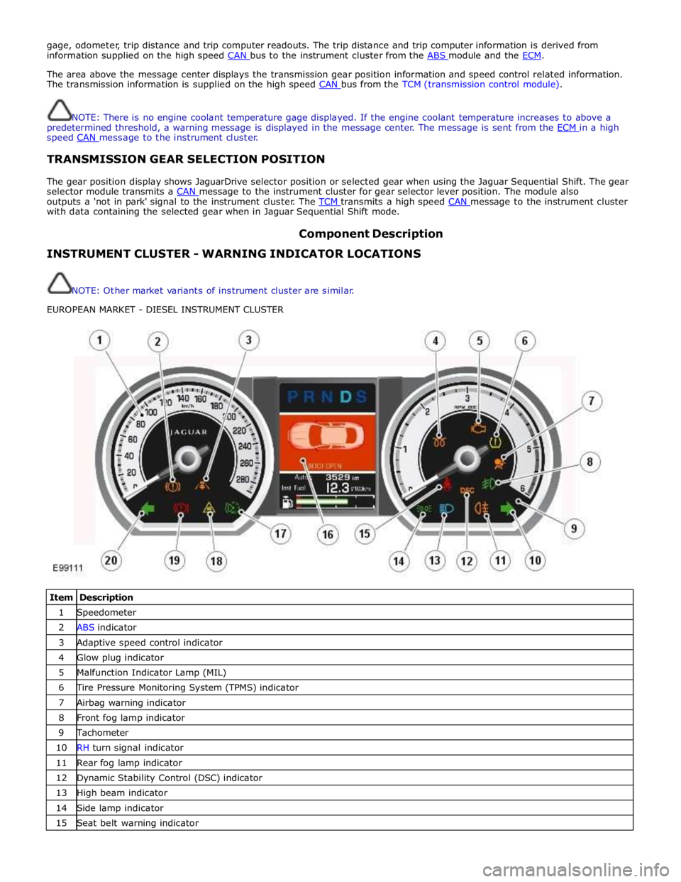
Component Description INSTRUMENT CLUSTER - WARNING INDICATOR LOCATIONS
NOTE: Other market variants of instrument cluster are similar.
EUROPEAN MARKET - DIESEL INSTRUMENT CLUSTER
Item Description 1 Speedometer 2 ABS indicator 3 Adaptive speed control indicator 4 Glow plug indicator 5 Malfunction Indicator Lamp (MIL) 6 Tire Pressure Monitoring System (TPMS) indicator 7 Airbag warning indicator 8 Front fog lamp indicator 9 Tachometer 10 RH turn signal indicator 11 Rear fog lamp indicator 12 Dynamic Stability Control (DSC) indicator 13 High beam indicator 14 Side lamp indicator 15 Seat belt warning indicator
Page 1795 of 3039
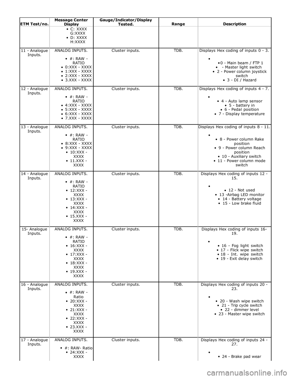
ETM Test/no. Message Center Display Gauge/Indicator/Display
Tested.
Range
Description C: XXXX
G:XXXX
D: XXXX
H:XXXX 11 - Analogue
Inputs. ANALOG INPUTS.
#: RAW -
RATIO
0:XXX - XXXX
1:XXX - XXXX
2:XXX - XXXX
3.XXX - XXXX Cluster inputs. TDB. Displays Hex coding of inputs 0 - 3.
0 - Main beam / FTP 1
- Master light switch
2 - Power column joystick
switch
3 - DI / Hazard 12 - Analogue
Inputs. ANALOG INPUTS.
#: RAW -
RATIO
4:XXX - XXXX
5:XXX - XXXX
6:XXX - XXXX
7.XXX - XXXX Cluster inputs. TDB. Displays Hex coding of inputs 4 - 7.
4 - Auto lamp sensor
5 - battery in
6 - Pedal position
7 - Display temperature 13 - Analogue
Inputs. ANALOG INPUTS.
#: RAW -
RATIO
8:XXX - XXXX
9:XXX - XXXX
10:XXX -
XXXX
11.XXX -
XXXX Cluster inputs. TDB. Displays Hex coding of inputs 8 - 11.
8 - Power column Rake
position
9 - Power column Reach
position
10 - Auxiliary switch
11 - Power column mode
switch 14 - Analogue
Inputs. ANALOG INPUTS.
#: RAW -
RATIO
12:XXX -
XXXX
13:XXX -
XXXX
14:XXX -
XXXX
15.XXX -
XXXX Cluster inputs. TDB.
Displays Hex coding of inputs 12 -
15.
12 - Not used
13 -Airbag LED monitor
14 - Battery voltage
15 - Low brake fluid 15- Analogue
Inputs. ANALOG INPUTS.
#: RAW -
RATIO
16:XXX -
XXXX
17:XXX -
XXXX
18:XXX -
XXXX
19.XXX -
XXXX Cluster inputs. TDB.
Displays Hex coding of inputs 16-
19.
16 - Fog light switch
17 - Flick wipe switch
18 - Int. wipe switch
19 - Exit delay switch 16 - Analogue
Inputs. ANALOG INPUTS.
#: RAW -
Ratio
20:XXX -
XXXX
21:XXX -
XXXX
22:XXX -
XXXX
23.XXX -
XXXX Cluster inputs. TDB.
Displays Hex coding of inputs 20 -
23.
20 - Wash wipe switch
21 - Trip cycle switch
22 - dimmer level
23 - Master wipe switch 17 - Analogue
Inputs. ANALOG INPUTS.
#: RAW- Ratio
24:XXX -
XXXX Cluster inputs. TDB.
Displays Hex coding of inputs 24 -
27.
24 - Brake pad wear
Page 1868 of 3039
Any actions must be carried out in accordance with the table shown in the Determining Battery Condition section (Section 6)
of this procedure. The details must be recorded on the New Vehicle Storage Form which is part of the new vehicle storage
document.
For additional information, refer to: New Vehicle Storage Form (100-11 Vehicle Transportation Aids and Vehicle Storage, Description and Operation).
4.3 PDI / DELIVERY TO CUSTOMER
Before the vehicle is handed over to the customer and as part of the PDI, the condition of the battery needs to be confirmed.
The battery condition must be checked in accordance with the battery test process utilizing a JLR approved tester as outlined
in the Equipment section (Section 5) of this procedure.
NOTE: The Midtronics code from the tester must be recorded on the form.
Any actions must be carried out in accordance with the table shown in the Determining Battery Condition section (Section 6)
of this procedure. The details must be recorded on the New Vehicle Storage Form which is part of the new vehicle storage
document.
For additional information, refer to: New Vehicle Storage Form (100-11 Vehicle Transportation Aids and Vehicle Storage, Description and Operation).
4.4 REPLACEMENT BATTERIES FOR SERVICE
All service replacement batteries must have the battery condition checked within 24 hours of receipt and controlled on a ‘First
In First Out’ basis to ensure batteries are not allowed to age unnecessarily.
For batteries in storage and not yet fitted to a vehicle, they must be stored in a dry environment, not in direct sunlight or
under any direct heat source. Any batteries exhibiting any forms of damage or corrosion must not be fitted to any vehicle. Any
batteries which are dropped must be scrapped, this applies even if no external damage is apparent.
The battery condition must be checked every 30 days in accordance with the battery test process utilizing a JLR approved
tester as outlined in the Equipment section (Section 5) of this procedure.
Any actions must be carried out in accordance with the table shown in the Determining Battery Condition section (Section 6)
of this procedure.The details must be recorded on the New Vehicle Storage Form which is part of the new vehicle storage
document.
For additional information, refer to: New Vehicle Storage Form (100-11 Vehicle Transportation Aids and Vehicle Storage, Description and Operation).
4.5 BATTERY MAINTENANCE
Any battery whether it is in a vehicle or a replacement part must be tested and/or re-charged every 30 days and MUST be
re-charged after every 90 day period.
4.6 BATTERY TEST PROCESS
It is recommended that this test is conducted at least 24 hours after the vehicle engine has been run or the battery charged to
avoid the need of surface charge removal. If time constraints make this unacceptable then the surface charge must be
removed.
Surface Charge Removal
A vehicle which has had its battery charged or been driven in a 24 hour period before the test, must have its surface charge
removed.
Turn on the ignition (power mode 6) but do not start the vehicle
Switch on the headlamps on high beam for a minimum 3 minutes
Switch off the headlamps
Wait a minimum of 5 minutes before recording test results for any battery measurements
Battery Test
The battery may be tested either on a bench or on the vehicle.
The battery condition must be checked in accordance with the battery test process utilizing a JLR approved tester as outlined
in the Equipment section (Section 5) of this procedure.
NOTE: The Midtronics code from the tester must be recorded on the form.
Any actions must be carried out in accordance with the table shown in the Determining Battery Condition section (Section 6)
of this procedure. The details must be recorded on the New Vehicle Storage Form which is part of the new vehicle storage
document.
For additional information, refer to: New Vehicle Storage Form (100-11 Vehicle Transportation Aids and Vehicle Storage, Description and Operation).
CAUTION: DO NOT connect the tester to any other circuit or chassis point other than the battery negative terminal.
Page 1890 of 3039
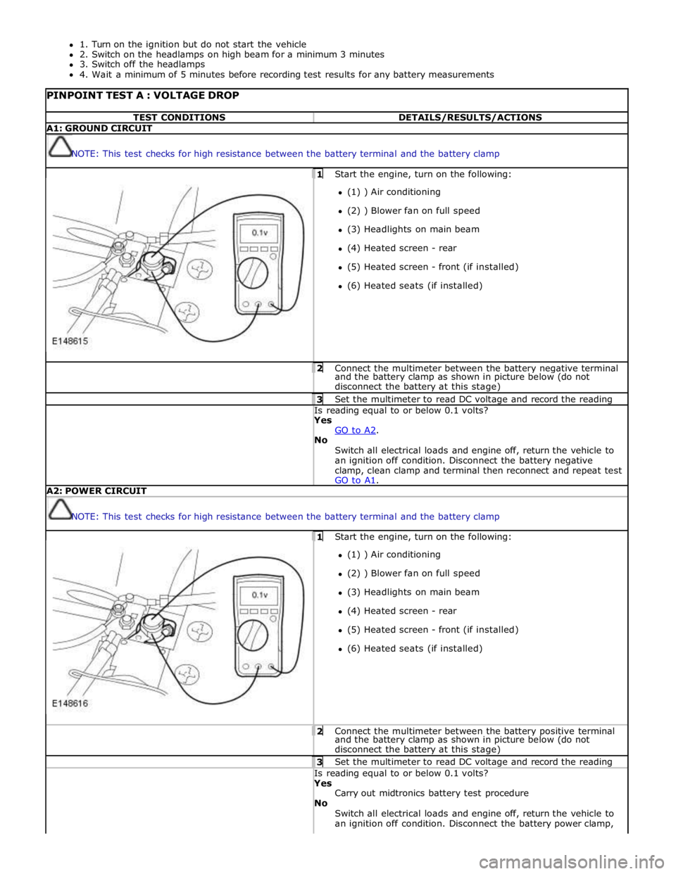
1. Turn on the ignition but do not start the vehicle
2. Switch on the headlamps on high beam for a minimum 3 minutes
3. Switch off the headlamps
4. Wait a minimum of 5 minutes before recording test results for any battery measurements
PINPOINT TEST A : VOLTAGE DROP TEST CONDITIONS DETAILS/RESULTS/ACTIONS A1: GROUND CIRCUIT
NOTE: This test checks for high resistance between the battery terminal and the battery clamp 1 Start the engine, turn on the following: (1) ) Air conditioning
(2) ) Blower fan on full speed
(3) Headlights on main beam
(4) Heated screen - rear
(5) Heated screen - front (if installed)
(6) Heated seats (if installed) 2 Connect the multimeter between the battery negative terminal and the battery clamp as shown in picture below (do not
disconnect the battery at this stage) 3 Set the multimeter to read DC voltage and record the reading Is reading equal to or below 0.1 volts? Yes
GO to A2. No
Switch all electrical loads and engine off, return the vehicle to
an ignition off condition. Disconnect the battery negative
clamp, clean clamp and terminal then reconnect and repeat test
GO to A1. A2: POWER CIRCUIT
NOTE: This test checks for high resistance between the battery terminal and the battery clamp 1 Start the engine, turn on the following: (1) ) Air conditioning
(2) ) Blower fan on full speed
(3) Headlights on main beam
(4) Heated screen - rear
(5) Heated screen - front (if installed)
(6) Heated seats (if installed) 2 Connect the multimeter between the battery positive terminal and the battery clamp as shown in picture below (do not
disconnect the battery at this stage) 3 Set the multimeter to read DC voltage and record the reading Is reading equal to or below 0.1 volts? Yes
Carry out midtronics battery test procedure
No
Switch all electrical loads and engine off, return the vehicle to
an ignition off condition. Disconnect the battery power clamp,
Page 1897 of 3039
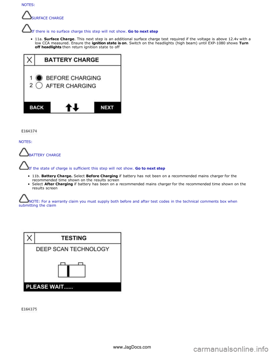
NOTES:
BATTERY
CHARGE
If
the
state
of
charge
is
sufficient
this
step
will
not
show.
Go
to
next
step
11b.
Battery
Charge.
Select
Before
Charging
if
battery
has
not
been
on
a
recommended
mains
charger
for
the
recommended
time
shown
on
the
results
screen
Select
After
Charging
if
battery
has
been
on
a
recommended
mains
charger
for
the
recommended
time
shown
on
the
results
screen
NOTE:
For
a
warranty
claim
you
must
supply
both
before
and
after
test
codes
in
the
technical
comments
box
when
submitting
the
claim
NOTES:
SURFACECHARGE
Ifthereisnosurfacechargethisstepwillnotshow.Gotonextstep
11a.SurfaceCharge.Thisnextstepisanadditionalsurfacechargetestrequiredifthevoltageisabove12.4vwith a
lowCCAmeasured.Ensuretheignitionstateis on.Switchontheheadlights(highbeam)untilEXP-1080showsTurn
offheadlightsthenreturnignitionstatetooffwww.JagDocs.com
Page 1958 of 3039
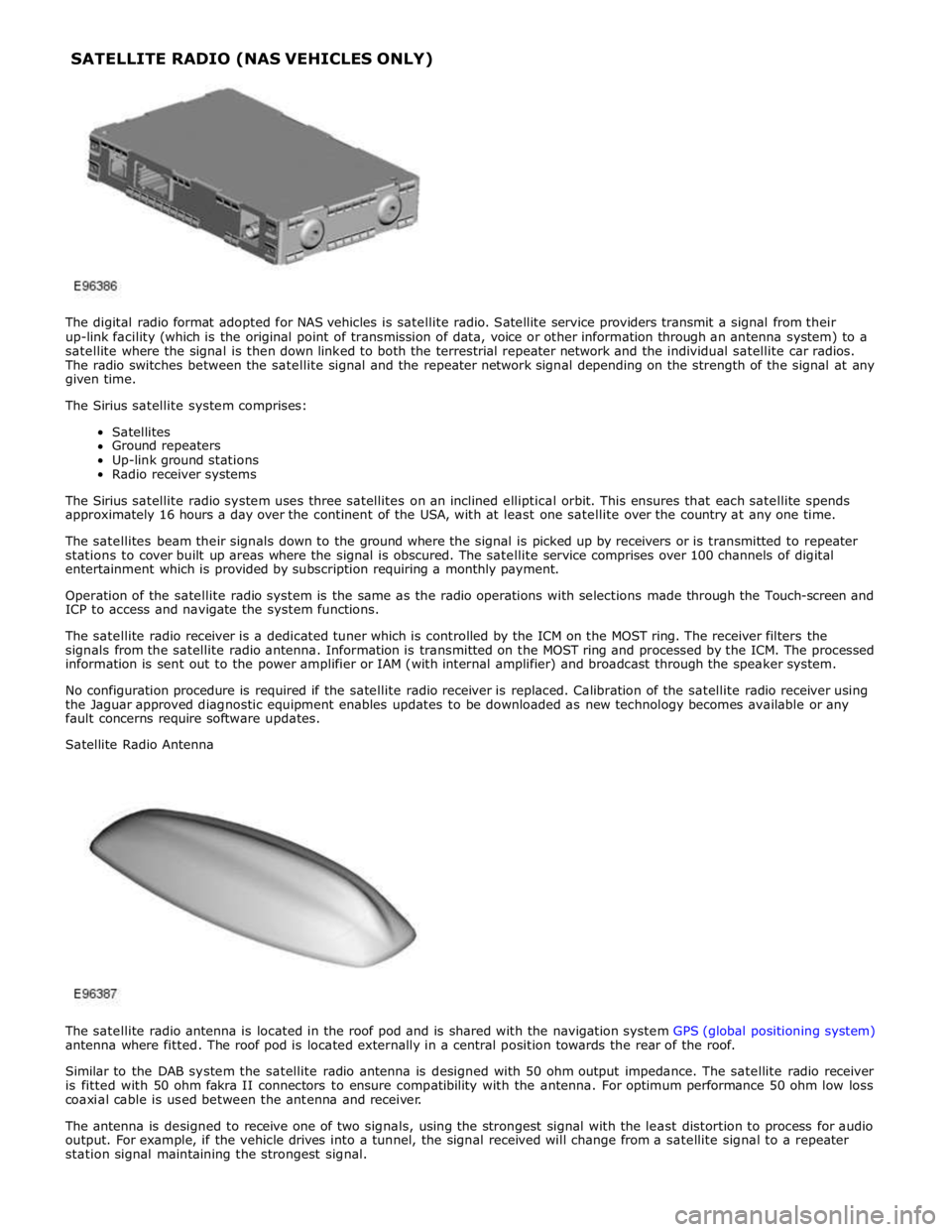
The digital radio format adopted for NAS vehicles is satellite radio. Satellite service providers transmit a signal from their
up-link facility (which is the original point of transmission of data, voice or other information through an antenna system) to a
satellite where the signal is then down linked to both the terrestrial repeater network and the individual satellite car radios.
The radio switches between the satellite signal and the repeater network signal depending on the strength of the signal at any
given time.
The Sirius satellite system comprises:
Satellites
Ground repeaters
Up-link ground stations
Radio receiver systems
The Sirius satellite radio system uses three satellites on an inclined elliptical orbit. This ensures that each satellite spends
approximately 16 hours a day over the continent of the USA, with at least one satellite over the country at any one time.
The satellites beam their signals down to the ground where the signal is picked up by receivers or is transmitted to repeater
stations to cover built up areas where the signal is obscured. The satellite service comprises over 100 channels of digital
entertainment which is provided by subscription requiring a monthly payment.
Operation of the satellite radio system is the same as the radio operations with selections made through the Touch-screen and
ICP to access and navigate the system functions.
The satellite radio receiver is a dedicated tuner which is controlled by the ICM on the MOST ring. The receiver filters the
signals from the satellite radio antenna. Information is transmitted on the MOST ring and processed by the ICM. The processed
information is sent out to the power amplifier or IAM (with internal amplifier) and broadcast through the speaker system.
No configuration procedure is required if the satellite radio receiver is replaced. Calibration of the satellite radio receiver using
the Jaguar approved diagnostic equipment enables updates to be downloaded as new technology becomes available or any
fault concerns require software updates.
Satellite Radio Antenna
The satellite radio antenna is located in the roof pod and is shared with the navigation system GPS (global positioning system)
antenna where fitted. The roof pod is located externally in a central position towards the rear of the roof.
Similar to the DAB system the satellite radio antenna is designed with 50 ohm output impedance. The satellite radio receiver
is fitted with 50 ohm fakra II connectors to ensure compatibility with the antenna. For optimum performance 50 ohm low loss
coaxial cable is used between the antenna and receiver.
The antenna is designed to receive one of two signals, using the strongest signal with the least distortion to process for audio
output. For example, if the vehicle drives into a tunnel, the signal received will change from a satellite signal to a repeater
station signal maintaining the strongest signal. SATELLITE RADIO (NAS VEHICLES ONLY)
Page 2019 of 3039

Low beam headlamp bulb - Vehicles with conventional headlamps - non Federal H7 Low beam headlamp bulb - Vehicles with conventional headlamps - Federal H11 Low beam headlamp bulb - Vehicles with xenon headlamps D1S High beam headlamp bulb H7 Cornering lamp bulb H8 Side repeater lamp bulb WY5W Side marker lamp bulb - Federal W5W Front turn signal lamp bulb - non Federal PY21W Front turn signal lamp bulb - Federal 3457 AK Rear turn signal lamp bulb PY19W Front side/parking lamp bulb - Vehicles built up to 01/2009 W5W halogen cool blue Front side/parking lamp bulb - Vehicles built 02/2009 onwards W5W Reversing lamp bulb PS19W