2010 JAGUAR XFR keyless
[x] Cancel search: keylessPage 1794 of 3039
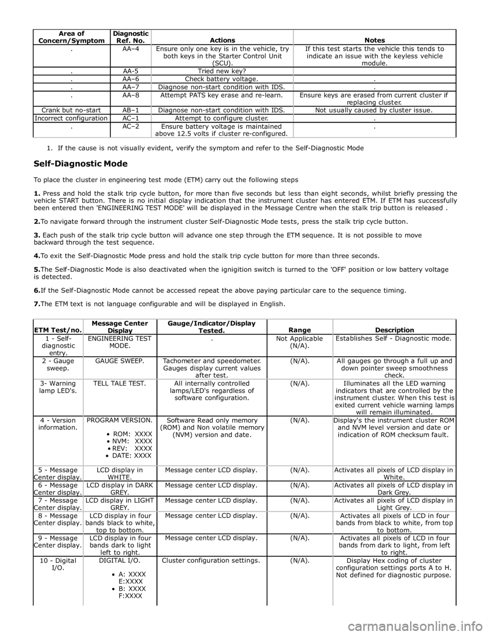
Area of
Concern/Symptom Diagnostic
Ref. No.
Actions
Notes . AA–4
Ensure only one key is in the vehicle, try
both keys in the Starter Control Unit (SCU). If this test starts the vehicle this tends to
indicate an issue with the keyless vehicle
module. . AA-5 Tried new key? . AA–6 Check battery voltage. . . AA–7 Diagnose non-start condition with IDS. . . AA–8 Attempt PATS key erase and re-learn.
Ensure keys are erased from current cluster if
replacing cluster. Crank but no-start AB–1 Diagnose non-start condition with IDS. Not usually caused by cluster issue. Incorrect configuration AC–1 Attempt to configure cluster. . . AC–2
Ensure battery voltage is maintained
above 12.5 volts if cluster re-configured. .
1. If the cause is not visually evident, verify the symptom and refer to the Self-Diagnostic Mode
Self-Diagnostic Mode
To place the cluster in engineering test mode (ETM) carry out the following steps
1. Press and hold the stalk trip cycle button, for more than five seconds but less than eight seconds, whilst briefly pressing the
vehicle START button. There is no initial display indication that the instrument cluster has entered ETM. If ETM has successfully
been entered then 'ENGINEERING TEST MODE' will be displayed in the Message Centre when the stalk trip button is released .
2. To navigate forward through the instrument cluster Self-Diagnostic Mode tests, press the stalk trip cycle button.
3. Each push of the stalk trip cycle button will advance one step through the ETM sequence. It is not possible to move
backward through the test sequence.
4. To exit the Self-Diagnostic Mode press and hold the stalk trip cycle button for more than three seconds.
5. The Self-Diagnostic Mode is also deactivated when the ignigition switch is turned to the 'OFF' position or low battery voltage
is detected.
6. If the Self-Diagnostic Mode cannot be accessed repeat the above paying particular care to the sequence timing.
7. The ETM text is not language configurable and will be displayed in English.
ETM Test/no. Message Center Display Gauge/Indicator/Display
Tested.
Range
Description 1 - Self-
diagnostic entry. ENGINEERING TEST
MODE. .
Not Applicable
(N/A). Establishes Self - Diagnostic mode. 2 - Gauge
sweep. GAUGE SWEEP.
Tachometer and speedometer.
Gauges display current values
after test. (N/A).
All gauges go through a full up and
down pointer sweep smoothness
check. 3- Warning
lamp LED's. TELL TALE TEST.
All internally controlled
lamps/LED's regardless of
software configuration. (N/A).
Illuminates all the LED warning
indicators that are controlled by the
instrument cluster. When this test is
exited current vehicle warning lamps
will remain illuminated. 4 - Version
information. PROGRAM VERSION.
ROM: XXXX
NVM: XXXX
REV: XXXX
DATE: XXXX Software Read only memory
(ROM) and Non volatile memory
(NVM) version and date. (N/A).
Display's the instrument cluster ROM
and NVM level version and date or
indication of ROM checksum fault. 5 - Message
Center display. LCD display in
WHITE. Message center LCD display. (N/A).
Activates all pixels of LCD display in
White. 6 - Message
Center display. LCD display in DARK
GREY. Message center LCD display. (N/A).
Activates all pixels of LCD display in
Dark Grey. 7 - Message
Center display. LCD display in LIGHT
GREY. Message center LCD display. (N/A).
Activates all pixels of LCD display in Light Grey. 8 - Message
Center display. LCD display in four
bands black to white, top to bottom. Message center LCD display. (N/A).
Activates all pixels of LCD in four
bands from black to white, from top
to bottom. 9 - Message
Center display. LCD display in four
bands dark to light
left to right. Message center LCD display. (N/A).
Activates all pixels of LCD in four
bands from dark to light, from left
to right. 10 - Digital
I/O. DIGITAL I/O.
A: XXXX
E:XXXX
B: XXXX
F:XXXX Cluster configuration settings. (N/A).
Display Hex coding of cluster
configuration settings ports A to H.
Not defined for diagnostic purpose.
Page 1797 of 3039
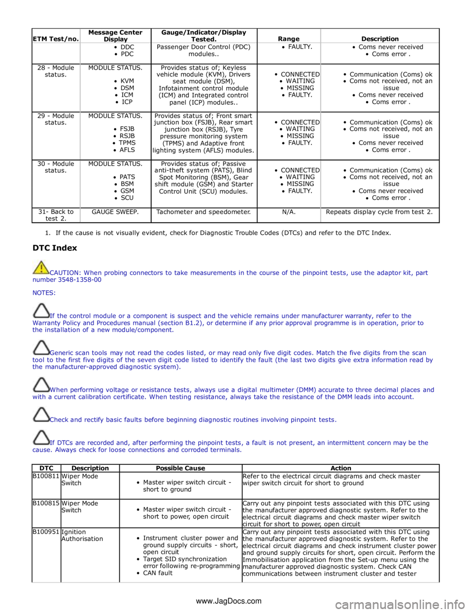
ETM Test/no. Message Center Display Gauge/Indicator/Display
Tested.
Range
Description DDC
PDC Passenger Door Control (PDC)
modules.. FAULTY.
Coms never received
Coms error . 28 - Module MODULE STATUS. Provides status of; Keyless
CONNECTED
Communication (Coms) ok status. vehicle module (KVM), Drivers KVM
seat module (DSM), WAITING Coms not received, not an DSM
Infotainment control module MISSING issue ICM
(ICM) and Integrated control FAULTY. Coms never received ICP
panel (ICP) modules.. Coms error . 29 - Module MODULE STATUS. Provides status of; Front smart
CONNECTED
Communication (Coms) ok status. junction box (FSJB), Rear smart FSJB
junction box (RSJB), Tyre WAITING Coms not received, not an RSJB
pressure monitoring system MISSING issue TPMS
(TPMS) and Adaptive front FAULTY. Coms never received AFLS
lighting system (AFLS) modules. Coms error . 30 - Module MODULE STATUS. Provides status of; Passive
CONNECTED
Communication (Coms) ok status. anti-theft system (PATS), Blind PATS
Spot Monitoring (BSM), Gear WAITING Coms not received, not an BSM
shift module (GSM) and Starter MISSING issue GSM
Control Unit (SCU) modules. FAULTY. Coms never received SCU Coms error . 31- Back to
test 2. GAUGE SWEEP. Tachometer and speedometer. N/A. Repeats display cycle from test 2.
1. If the cause is not visually evident, check for Diagnostic Trouble Codes (DTCs) and refer to the DTC Index.
DTC Index
CAUTION: When probing connectors to take measurements in the course of the pinpoint tests, use the adaptor kit, part
number 3548-1358-00
NOTES:
If the control module or a component is suspect and the vehicle remains under manufacturer warranty, refer to the
Warranty Policy and Procedures manual (section B1.2), or determine if any prior approval programme is in operation, prior to
the installation of a new module/component.
Generic scan tools may not read the codes listed, or may read only five digit codes. Match the five digits from the scan
tool to the first five digits of the seven digit code listed to identify the fault (the last two digits give extra information read by
the manufacturer-approved diagnostic system).
When performing voltage or resistance tests, always use a digital multimeter (DMM) accurate to three decimal places and
with a current calibration certificate. When testing resistance, always take the resistance of the DMM leads into account.
Check and rectify basic faults before beginning diagnostic routines involving pinpoint tests.
If DTCs are recorded and, after performing the pinpoint tests, a fault is not present, an intermittent concern may be the
cause. Always check for loose connections and corroded terminals.
DTC Description Possible Cause Action B100811
Wiper Mode
Switch
Master wiper switch circuit -
short to ground Refer to the electrical circuit diagrams and check master
wiper switch circuit for short to ground B100815
Wiper Mode
Switch
Master wiper switch circuit -
short to power, open circuit Carry out any pinpoint tests associated with this DTC using
the manufacturer approved diagnostic system. Refer to the
electrical circuit diagrams and check master wiper switch
circuit for short to power, open circuit B100951
Ignition
Authorisation
Instrument cluster power and
ground supply circuits - short,
open circuit
Target SID synchronization
error following re-programming
CAN fault Carry out any pinpoint tests associated with this DTC using
the manufacturer approved diagnostic system. Refer to the
electrical circuit diagrams and check instrument cluster power
and ground supply circuits for short, open circuit. Perform the
Immobilisation application from the Set-up menu using the
manufacturer approved diagnostic system. Check CAN
communications between instrument cluster and tester www.JagDocs.com
Page 1805 of 3039

DTC Description Possible Cause Action U013900
Lost
Communication
with Suspension
Control Module 'B'
Loss of CAN communication
with adaptive damping module Carry out any pinpoint tests associated with this DTC using
the manufacturer approved diagnostic system. Check
adaptive damping module for DTCs and refer to the relevant
DTC Index U014000
Lost
Communication
With Body
Control Module
Loss of CAN communication
with CJB Carry out any pinpoint tests associated with this DTC using
the manufacturer approved diagnostic system. Check CJB for
DTCs and refer to the relevant DTC Index U014200
Lost
Communication
With Body
Control Module
"B"
Loss of CAN communication
with RJB Carry out any pinpoint tests associated with this DTC using
the manufacturer approved diagnostic system. Check RJB for
DTCs and refer to the relevant DTC Index U015100
Lost
Communication
With Restraints
Control Module
Loss of CAN communication
with RCM Carry out any pinpoint tests associated with this DTC using
the manufacturer approved diagnostic system. Check RCM for
DTCs and refer to the relevant DTC Index U015600
Lost
Communication
with Information
Centre 'A'
Loss of CAN communication
with information and
entertainment control module Carry out any pinpoint tests associated with this DTC using
the manufacturer approved diagnostic system. Check
information and entertainment control module for DTCs and
refer to the relevant DTC Index U016400
Lost
Communication
with HVAC
Control Module
Loss of CAN communication
with climate control module Carry out any pinpoint tests associated with this DTC using
the manufacturer approved diagnostic system. Check climate
control module for DTCs and refer to the relevant DTC Index U019900
Lost
Communication
with Door Control
Module 'A'
Loss of CAN communication
with driver door module (DDM) Carry out any pinpoint tests associated with this DTC using
the manufacturer approved diagnostic system. Check DDM for
DTCs and refer to the relevant DTC Index U020000
Lost
Communication
with Door Control
Module 'B'
Loss of CAN communication
with passenger door module
(PDM) Carry out any pinpoint tests associated with this DTC using
the manufacturer approved diagnostic system. Check PDM for
DTCs and refer to the relevant DTC Index U020800
Lost
Communication
with Seat Control
Module 'A'
Loss of CAN communication
with driver seat module (DSM) Carry out any pinpoint tests associated with this DTC using
the manufacturer approved diagnostic system. Check DSM for
DTCs and refer to the relevant DTC Index U021400
Lost
Communication
with Remote
Function
Actuation
Loss of CAN communication
with keyless vehicle module
(KVM) Carry out any pinpoint tests associated with this DTC using
the manufacturer approved diagnostic system. Check KVM for
DTCs and refer to the relevant DTC Index U024100
Lost
Communication
with Headlamp
Control Module 'A'
Loss of CAN communication
with headlamp control module Carry out any pinpoint tests associated with this DTC using
the manufacturer approved diagnostic system. Check
headlamp control module for DTCs and refer to the relevant
DTC Index U025000
Lost
Communication
with Impact
Classification System Module
Loss of CAN communication
with pedestrian protection
module Carry out any pinpoint tests associated with this DTC using
the manufacturer approved diagnostic system. Check
pedestrian protection module for DTCs and refer to the
relevant DTC Index U025600
Lost
Communication
with Front
Controls Interface
Module 'A'
Loss of CAN communication
with integrated control panel Carry out any pinpoint tests associated with this DTC using
the manufacturer approved diagnostic system. Check
integrated control panel for DTCs and refer to the relevant
DTC Index U030000
Internal Control
Module Software
Incompatibility
Invalid configuration message
is received Re-configure the RJB using the manufacturer approved
diagnostic system. Clear the DTC and retest. If the DTC is
still logged suspect the instrument cluster, refer to the new
module/component installation note at the top of the DTC
Index U040268
Invalid data
received from
TCM
Algorithm based failures -
events information Check TCM for DTCs and refer to the relevant DTC Index U200411
Auxiliary Switch
Pack
Auxiliary switch signal circuit -
short to ground Refer to the electrical circuit diagrams and check auxiliary
switch signal circuit for short to ground U200415
Auxiliary Switch
Pack
Auxiliary switch signal circuit -
short to power, open circuit Carry out any pinpoint tests associated with this DTC using
the manufacturer approved diagnostic system. Refer to the
electrical circuit diagrams and check auxiliary switch signal
circuit for short to power, open circuit
Page 1866 of 3039

Published: 07-Aug-2014
Battery and Charging System - General Information - Battery Care
Requirements
Description and Operation
1. INTRODUCTION
This document defines the requirements for care and maintenance of batteries, and the standard of battery care at dealers and
retailers for new vehicles.
This applies to all types of 12 Volt Lead Acid Batteries used in Jaguar and Land Rover vehicles whether they are conventional
flooded technology or Absorbed Glass Mat (AGM – also known as Valve Regulated Lead Acid (VRLA)) technology and also
applies to both Primary, Secondary and Auxiliary Batteries. AGM batteries offer improved resistance to cycling as seen in stop
start applications.
In order to prevent damage to the battery and ensure a satisfactory service life, all processes detailed within this document
must be rigorously adhered to.
It is equally important therefore to note the following key points:
All new vehicles leave the factory with either a transit relay installed and/or have a transit mode programmed into the
vehicle control modules. The transit relay must be removed and the transit mode disabled (where applicable) using an
approved diagnostic system, NOT MORE THAN 72 HOURS before the customer takes delivery.
The battery can be discharged by the following mechanisms:
- Self Discharge: - A lead acid battery will very slowly discharge itself due to its own internal chemical processes
whether it is connected to a vehicle or not.
- Quiescent Discharge: - The vehicle electrical systems when connected to the battery will draw charge from the
battery.
12 Volt Lead Acid Batteries rely on internal chemical processes to create a voltage and deliver current. These processes and
the internal chemical structure of the battery can be damaged if the battery is allowed to discharge over a number of weeks /
months, or is left in a discharged state for a lengthy time period.
On vehicles with conventional ignition keys, these must not be left in the ignition lock barrel when the transit relay
has been removed, otherwise quiescent current will increase and the battery will discharge more rapidly.
For keyless vehicles, the Smart Key must be stored at least 5m (16 ft) away from the vehicle when the vehicle is
parked or stored.
AGM Batteries are fully sealed and cannot have the electrolyte level topped up.
NOTE: Dealers and retailers involved in the storage / handling of vehicles and replacement batteries have a responsibility
to ensure that only a fully charged battery may be processed through the distribution selling chain.
2. GENERAL RULES FOR BATTERY CARE
2.1 Dealer Demonstration Vehicles
Vehicles used as dealer demonstrator(s), in a showroom, must be connected to a JLR approved showroom conditioner capable
of delivering 50 Amps. This will prevent the battery from being damaged.
2.2 Software Reflash, SDD work or Ignition On related workshop activities
Due to the high electrical current demand and high depth of discharge that can occur during vehicle software re-flash activities,
SDD work or ignition on (power mode 6) related work in the workshop, vehicles that are undergoing such activities MUST have a
JLR approved power supply capable of delivering 50 Amps or more.
2.3 Extended Vehicle Rework
For any extended vehicle rework that results in consuming vehicle power, either the battery should be disconnected or a JLR
approved power supply connected.
2.4 Jump Starting New vehicles before they have been delivered to the customer
It is the dealer / retailers responsibility to make sure the battery is not allowed to discharge by following the
instructions and processes defined in this manual.
However, if circumstances dictate that a new vehicle must be jump started due to a discharged battery whilst the
vehicle is in the dealer / retailers care, the battery on this vehicle must be replaced with a new one prior to delivery
to the customer at the dealer / retailers liability.
The vehicle should also undergo investigation as to why the battery became discharged.
Do not connect the jump starting cable to the negative (-) terminal of the battery. Always connect to the recommended
earth point. As defined in the owners handbook or service documentation for that vehicle. 2.5 AGM Batteries
AGM batteries must not be charged above 14.8 Volts. Doing so will damage them.
AGM Batteries must be tested with a capable battery tester as detailed in the Equipment section (Section 5) of this
Page 1871 of 3039

Published: 21-Dec-2012
Battery and Charging System - General Information - Quiescent Drain
Description and Operation
VEHICLE QUIESCENT CURRENT TESTING
On vehicles fitted with a Battery Monitoring System (BMS), the diagnostic routine for quiescent drain testing in the approved
Jaguar or Land Rover diagnostic system should be utilized.
If a customer complains of a vehicle battery that discharges continuously or when left for a prolonged period of time, it is
recommended that a quiescent drain test is performed as described below.
The battery drain should be measured using the approved Jaguar or Land Rover diagnostic system or a Digital Multi-Meter
(DVOM). A procedure for quiescent drain measurement using the diagnostic system is available in the Diagnosis and Testing
section of the Workshop Manual. The vehicle should be in the locked/armed state (for example vehicle alarm fully armed), all
doors, engine and luggage compartment lids are open and latched (so as to appear closed from an electrical point of view).
The test should take place after the vehicle has entered shutdown mode. The time taken for this to occur after the ignition is
switched off varies according to model (Refer to the Topix On line resource for details).
When the vehicle is armed, the effect of the security system Light Emitting Diode (LED) flashing is to cause a pulsation in the
measured current drain. In this case, either the average current should be taken (using a Digital Multi- Meter (DVOM) with an
averaging system) or the current reading taken, ignoring the brief high current peaks.
EQUIPMENT
Approved Jaguar or Land Rover diagnostic system with current probeOR Digital Multi-Meter (DVOM) with current probe.
METHOD OF MEASUREMENT
Using an Approved Jaguar or Land Rover Diagnostic System.
1. Switch off all electrical loads and ensure that the ignition is off
2. Connect the current probe to the approved Jaguar or Land Rover diagnostic system
3. Calibrate the probe
4. Install a clamp around the battery lead/junction box lead
5. Go to the Quiescent Current Testing section in this procedure
Using a digital multimeter
Do not use an in-line DVOM to measure the quiescent drain on vehicles fitted with an electronic throttle (for example XK 2006
onwards). The current exceeds the maximum amount the fuse in the DVOM is capable of handling.
1. Switch off all electrical loads and ensure that the ignition is off
2. Connect the current probe to the digital multmeter
3. Calibrate the probe
4. Install a clamp around the battery lead/junction box lead
5. Go to the Quiescent Current Testing section in this procedure
QUIESCENT CURRENT TESTING
1. Switch ignition to ‘on’ or select ignition mode in keyless vehicles and switch to ‘off’ (do not crank)
2. Remove key from ignition switch (if equipped)
3. Open and latch all doors, hood and luggage compartment lid
4. Lock the vehicle using the remote function on the remote handset. (Single lock only to avoid volumetric alarm arming)
5. Remove any other potential electrical drains such as accessories plugged into accessory sockets
6. Record the amperage readings after the shutdown period referenced in the Topix on line resource for details. Note all
cars from 10MY onwards and XK from 07MY and XF from 08MY should be less than 30mA after 30 minutes
7. Record the final reading on the battery report form
The preferred method of testing following an excessive current consumption figure is to use a current probe around individual
junction box leads to the various suspected circuits to identify a potential cause. This is in preference to the old method of
removing fuses for the following reasons:
The drain may be caused by a module remaining active and preventing the quiescent drain from reducing to normal
levels
The drain may be caused by a relay winding that is activated. Pulling the fuse can allow this to ‘reset’ and the drain will
be lost and go un-diagnosed
QUIESCENT DRAIN - TYPICAL VALUES
NOTE: The quiescent drain after the initial shutdown period should not exceed the value shown in the table.
Jaguar Quiescent Drain Values
MODEL SHUT DOWN PERIOD (minutes) TYPICAL VALUES BATTERY DRAIN (mA) XJS 3.2 60 <30 Sovereign 3.2 60 <37.3
Page 2058 of 3039
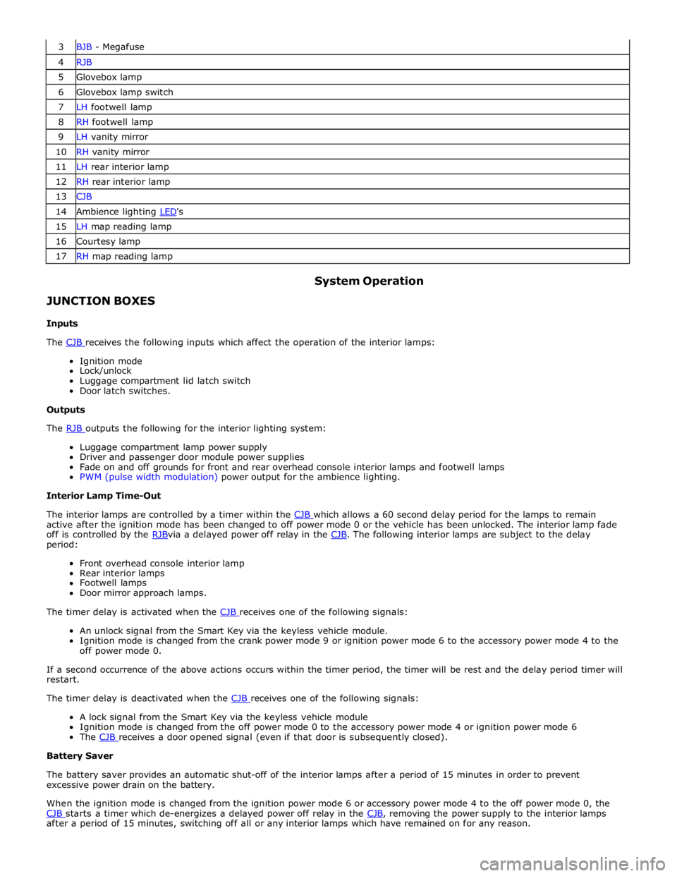
3 BJB - Megafuse 4 RJB 5 Glovebox lamp 6 Glovebox lamp switch 7 LH footwell lamp 8 RH footwell lamp 9 LH vanity mirror 10 RH vanity mirror 11 LH rear interior lamp 12 RH rear interior lamp 13 CJB 14 Ambience lighting LED's 15 LH map reading lamp 16 Courtesy lamp 17 RH map reading lamp
JUNCTION BOXES
Inputs System Operation
The CJB receives the following inputs which affect the operation of the interior lamps: Ignition mode
Lock/unlock
Luggage compartment lid latch switch
Door latch switches.
Outputs
The RJB outputs the following for the interior lighting system: Luggage compartment lamp power supply
Driver and passenger door module power supplies
Fade on and off grounds for front and rear overhead console interior lamps and footwell lamps
PWM (pulse width modulation) power output for the ambience lighting.
Interior Lamp Time-Out
The interior lamps are controlled by a timer within the CJB which allows a 60 second delay period for the lamps to remain active after the ignition mode has been changed to off power mode 0 or the vehicle has been unlocked. The interior lamp fade
off is controlled by the RJBvia a delayed power off relay in the CJB. The following interior lamps are subject to the delay period:
Front overhead console interior lamp
Rear interior lamps
Footwell lamps
Door mirror approach lamps.
The timer delay is activated when the CJB receives one of the following signals: An unlock signal from the Smart Key via the keyless vehicle module.
Ignition mode is changed from the crank power mode 9 or ignition power mode 6 to the accessory power mode 4 to the
off power mode 0.
If a second occurrence of the above actions occurs within the timer period, the timer will be rest and the delay period timer will
restart.
The timer delay is deactivated when the CJB receives one of the following signals: A lock signal from the Smart Key via the keyless vehicle module
Ignition mode is changed from the off power mode 0 to the accessory power mode 4 or ignition power mode 6
The CJB receives a door opened signal (even if that door is subsequently closed). Battery Saver
The battery saver provides an automatic shut-off of the interior lamps after a period of 15 minutes in order to prevent
excessive power drain on the battery.
When the ignition mode is changed from the ignition power mode 6 or accessory power mode 4 to the off power mode 0, the
CJB starts a timer which de-energizes a delayed power off relay in the CJB, removing the power supply to the interior lamps after a period of 15 minutes, switching off all or any interior lamps which have remained on for any reason.
Page 2059 of 3039
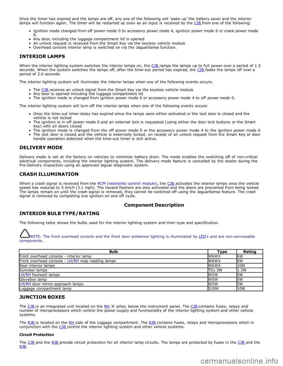
Once the timer has expired and the lamps are off, any one of the following will 'wake up' the battery saver and the interior
lamps will function again. The timer will be restarted as soon as an input is received by the CJB from one of the following:
Ignition mode changed from off power mode 0 to accessory power mode 4, ignition power mode 6 or crank power mode
9.
Any door, including the luggage compartment lid is opened
An unlock request is received from the Smart Key via the keyless vehicle module
Overhead console interior lamp is switched on via the JaguarSense function.
INTERIOR LAMPS
When the interior lighting system switches the interior lamps on, the CJB ramps the lamps up to full power over a period of 1.3 seconds. When the system switches the lamps off, after the time-out period has expired, the CJB fades the lamps off over a period of 2.6 seconds.
The interior lighting system will illuminate the interior lamps when one of the following events occurs:
The CJB receives an unlock signal from the Smart Key via the keyless vehicle module Any door is opened including the luggage compartment lid
The ignition mode is changed from ignition power mode 6 or accessory power mode 4 to off power mode 0.
The interior lighting system will turn off the interior lamps when one of the following events occurs:
Once the time-out timer delay has expired since the lamps were either activated or the last door is closed and the
vehicle is not locked
The ignition is in off power mode 0 and an external lock is requested (using either the door lock buttons or the Smart
Key) with all doors closed
The ignition mode is changed from the off power mode 0 or the accessory power mode 4 to the ignition power mode 6
The last door is closed and the vehicle is externally locked, on receipt of an unlock request from the Smart Key or door
handle operation detected when the time-out timer is still active.
DELIVERY MODE
Delivery mode is set at the factory on vehicles to minimize battery drain. The mode enables the switching off of non-critical
electrical components, including the interior lighting system. The delivery mode feature is cancelled by the dealer during the
Pre-Delivery Inspection using an approved Jaguar diagnostic system.
CRASH ILLUMINATION
When a crash signal is received from the RCM (restraints control module), the CJB activates the interior lamps once the vehicle speed has reduced to 5 km/h (3.1 mph). The hazard flashers are also activated and the doors are prevented from being locked.
The lamps remain on until the crash signal is removed, they cannot be switched off using the JaguarSense feature. The crash
signal is removed by completing one ignition on and off cycle.
INTERIOR BULB TYPE/RATING Component Description
The following table shows the bulbs used for the interior lighting system and their type and specification.
NOTE: The front overhead console and the front door ambience lighting is illuminated by LED's and are non-serviceable components.
Bulb Type Rating Front overhead console - interior lamp W6WX 6W Front overhead console - LH/RH map reading lamps W6WX 6W Rear interior lamps W6WX 10W Sunvisor lamps TS1.3W 1.3W LH/RH footwell lamps W5W 5W Glovebox lamp W5W 5W LH/RH door mirror approach lamps W5W 5W Luggage compartment lamp S10W 10W JUNCTION BOXES
The CJB is an integrated unit located on the RH 'A' pillar, below the instrument panel. The CJB contains fuses, relays and number of microprocessors which control the power supply and functionality of the interior lighting system and other vehicle
systems.
The RJB is located on the RH side of the luggage compartment. The RJB contains fuses, relays and microprocessors which in conjunction with the CJB control the interior lighting system and other vehicle systems. Circuit Protection
The CJB and the RJB provide circuit protection for all interior lamp circuits. The lamps are protected by fuses in the CJB and the RJB.
Page 2071 of 3039
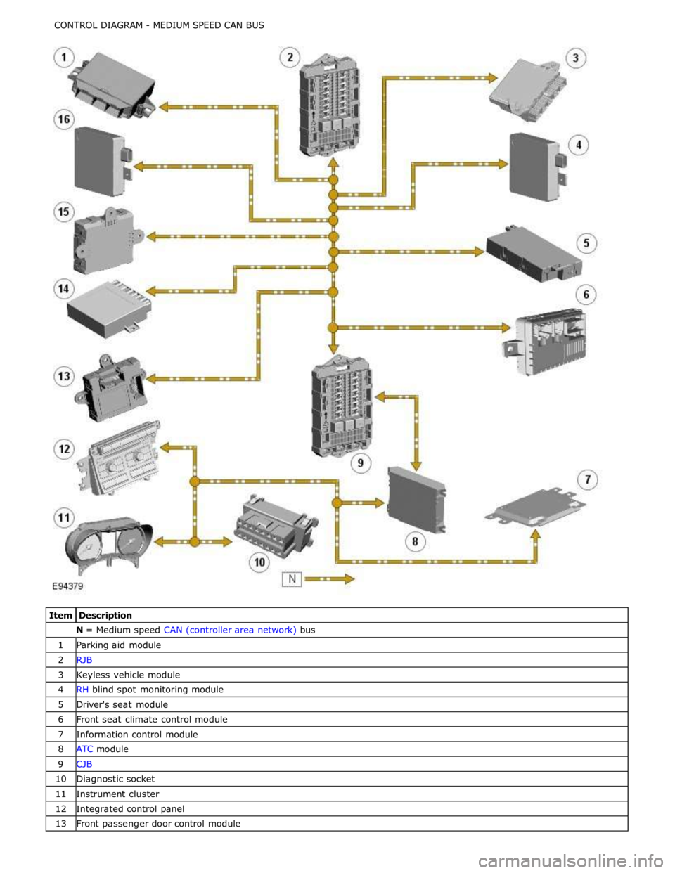
N = Medium speed CAN (controller area network) bus 1 Parking aid module 2 RJB 3 Keyless vehicle module 4 RH blind spot monitoring module 5 Driver's seat module 6 Front seat climate control module 7 Information control module 8 ATC module 9 CJB 10 Diagnostic socket 11 Instrument cluster 12 Integrated control panel 13 Front passenger door control module