2010 JAGUAR XFR Interior
[x] Cancel search: InteriorPage 2607 of 3039
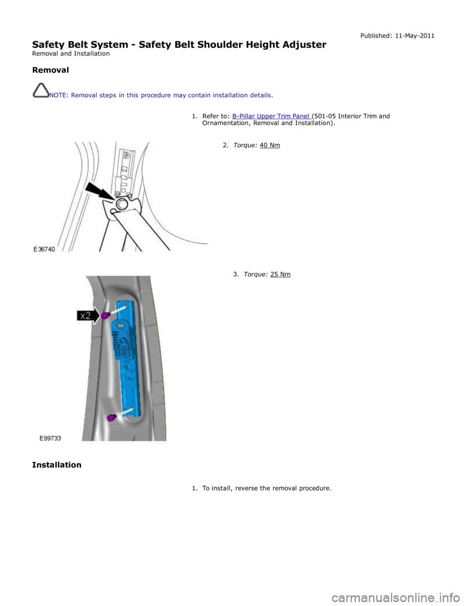
Safety Belt System - Safety Belt Shoulder Height Adjuster
Removal and Installation
Removal
NOTE: Removal steps in this procedure may contain installation details. Published: 11-May-2011
1. Refer to: B-Pillar Upper Trim Panel (501-05 Interior Trim and Ornamentation, Removal and Installation).
2. Torque: 40 Nm
Installation
3. Torque: 25 Nm
1. To install, reverse the removal procedure.
Page 2615 of 3039
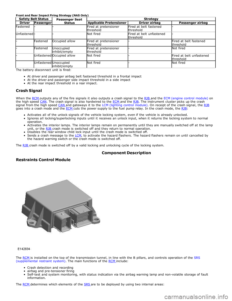
Driver Passenger Applicable Pretensioner Driver airbag Passenger airbag Fastened - -
Fired at pretensioner
threshold Fired at belt fastened
threshold - Unfastened - - Not fired
Fired at belt unfastened
threshold - - Fastened Occupied allow
Fired at pretensioner
threshold -
Fired at belt fastened
threshold - Fastened
Unoccupied inhibit/empty Fired at pretensioner
threshold - Not fired - Unfastened Occupied allow Not fired -
Fired at belt unfastened
threshold Unfastened
Unoccupied inhibit/empty Not fired - Not fired The battery disconnect unit is fired:
At driver and passenger airbag belt fastened threshold in a frontal impact
At the driver and passenger side impact threshold in a side impact
At the rear impact threshold in a rear impact.
Crash Signal
When the RCM outputs any of the fire signals it also outputs a crash signal to the RJB and the ECM (engine control module) on the high speed CAN. The crash signal is also hardwired to the ECM and the RJB. The instrument cluster picks up the crash signal from the high speed CAN and gateways it to the LCM (lighting control module). On receipt of the crash signal, the RJB goes into a crash mode and the ECM cuts the power supply to the fuel pump relay. In the crash mode, the RJB: Activates all of the unlock signals of the vehicle locking system, even if the vehicle is already unlocked.
Ignores all locking/superlocking inputs until it receives an unlock input, when it returns the locking system to normal
operation.
Activates the interior lamps. The interior lamps remain on permanently until they are manually switched off at the lamp
unit, or the RJB crash mode is switched off and they return to normal operation. Disables the rear window child lock input until the crash mode is switched off.
Sends a crash message to the LCM, to activate the hazard flashers. The hazard flashers remain on until cancelled by the hazard warning switch or the crash mode is switched off.
The RJB crash mode is switched off by a valid locking and unlocking cycle of the locking system.
Restraints Control Module Component Description
The RCM is installed on the top of the transmission tunnel, in line with the B pillars, and controls operation of the SRS (supplemental restraint system). The main functions of the RCM include:
Crash detection and recording
airbag and pre-tensioner firing
Self-test and system monitoring, with status indication via the airbag warning lamp and non-volatile storage of fault
information.
The RCM determines which elements of the SRS are to be deployed by using two internal areas:
Page 2628 of 3039
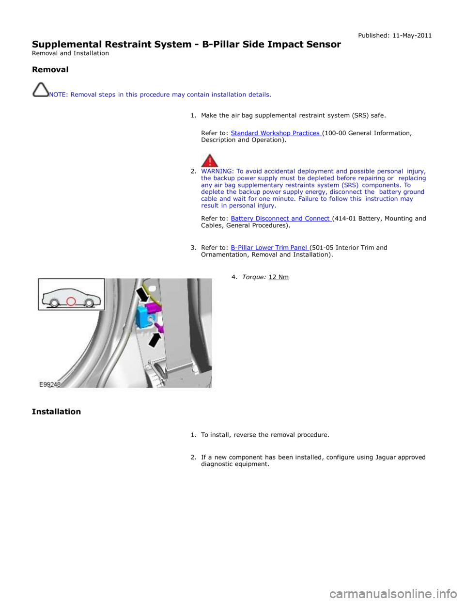
Supplemental Restraint System - B-Pillar Side Impact Sensor
Removal and Installation
Removal
NOTE: Removal steps in this procedure may contain installation details. Published: 11-May-2011
1. Make the air bag supplemental restraint system (SRS) safe.
Refer to: Standard Workshop Practices (100-00 General Information, Description and Operation).
2. WARNING: To avoid accidental deployment and possible personal injury,
the backup power supply must be depleted before repairing or replacing
any air bag supplementary restraints system (SRS) components. To
deplete the backup power supply energy, disconnect the battery ground
cable and wait for one minute. Failure to follow this instruction may
result in personal injury.
Refer to: Battery Disconnect and Connect (414-01 Battery, Mounting and Cables, General Procedures).
3. Refer to: B-Pillar Lower Trim Panel (501-05 Interior Trim and Ornamentation, Removal and Installation).
Installation
4. Torque: 12 Nm
1. To install, reverse the removal procedure.
2. If a new component has been installed, configure using Jaguar approved
diagnostic equipment.
Page 2653 of 3039
Supplemental Restraint System - Passenger Air Bag Module
Removal and Installation Published: 11-May-2011
Removal
NOTE: Removal steps in this procedure may contain installation details.
1. Refer to: Battery Disconnect and Connect (414-01 Battery, Mounting and Cables, General Procedures).
2. Refer to: Steering Wheel (211-04 Steering Column, Removal and Installation).
3. Refer to: Driver Side Register (412-01 Climate Control, Removal and Installation).
4. Refer to: Information and Entertainment Display (415-01A Information and Entertainment System, Removal and Installation).
5. Refer to: Instrument Panel Speaker (415-01A Information and Entertainment System, Removal and Installation).
6. Refer to: A-Pillar Trim Panel (501-05 Interior Trim and Ornamentation, Removal and Installation).
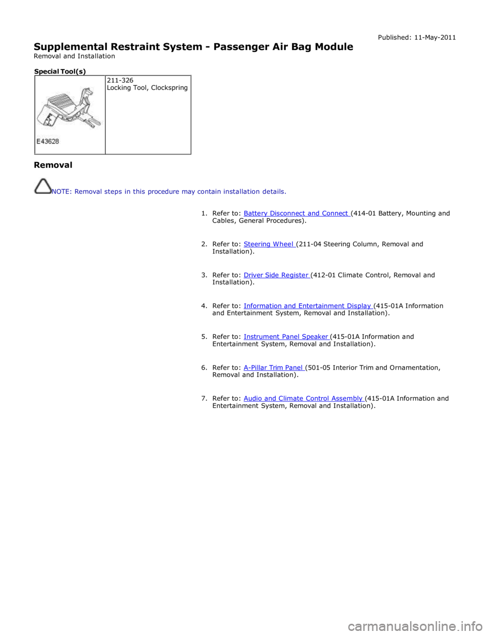
7. Refer to: Audio and Climate Control Assembly (415-01A Information and Entertainment System, Removal and Installation). 211-326
Locking Tool, Clockspring Special Tool(s)
Page 2673 of 3039
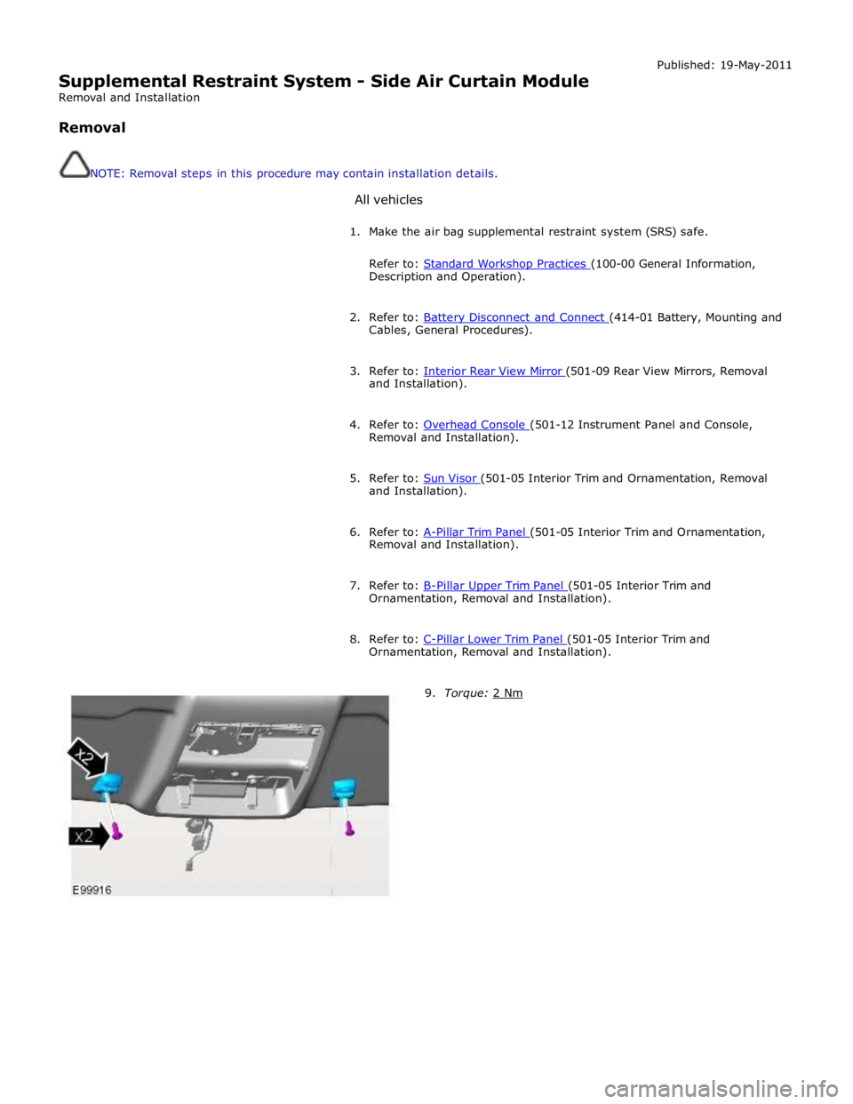
Supplemental Restraint System - Side Air Curtain Module
Removal and Installation
Removal
NOTE: Removal steps in this procedure may contain installation details.
All vehicles Published: 19-May-2011
1. Make the air bag supplemental restraint system (SRS) safe.
Refer to: Standard Workshop Practices (100-00 General Information, Description and Operation).
2. Refer to: Battery Disconnect and Connect (414-01 Battery, Mounting and Cables, General Procedures).
3. Refer to: Interior Rear View Mirror (501-09 Rear View Mirrors, Removal and Installation).
4. Refer to: Overhead Console (501-12 Instrument Panel and Console, Removal and Installation).
5. Refer to: Sun Visor (501-05 Interior Trim and Ornamentation, Removal and Installation).
6. Refer to: A-Pillar Trim Panel (501-05 Interior Trim and Ornamentation, Removal and Installation).
7. Refer to: B-Pillar Upper Trim Panel (501-05 Interior Trim and Ornamentation, Removal and Installation).
8. Refer to: C-Pillar Lower Trim Panel (501-05 Interior Trim and Ornamentation, Removal and Installation).
9. Torque: 2 Nm
Page 2710 of 3039
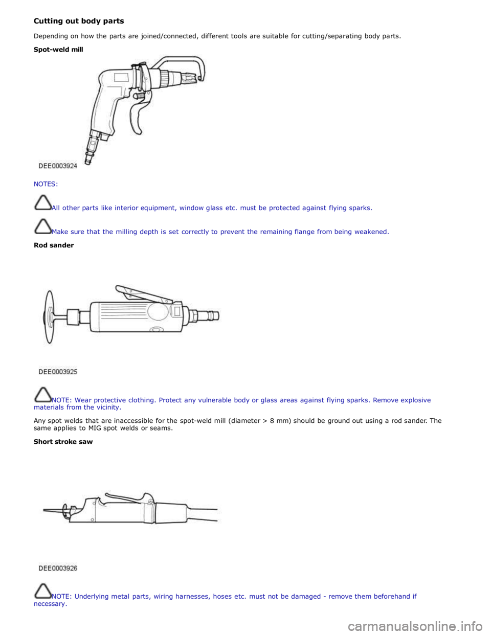
Cutting out body parts
Depending on how the parts are joined/connected, different tools are suitable for cutting/separating body parts.
NOTES:
All other parts like interior equipment, window glass etc. must be protected against flying sparks.
Make sure that the milling depth is set correctly to prevent the remaining flange from being weakened.
Rod sander
NOTE: Wear protective clothing. Protect any vulnerable body or glass areas against flying sparks. Remove explosive
materials from the vicinity.
Any spot welds that are inaccessible for the spot-weld mill (diameter > 8 mm) should be ground out using a rod sander. The
same applies to MIG spot welds or seams.
Short stroke saw
NOTE: Underlying metal parts, wiring harnesses, hoses etc. must not be damaged - remove them beforehand if
necessary. Spot-weld mill
Page 2718 of 3039
Part N-umber
Body Repairs - Corrosion Protection - Corrosion Protection
Description and Operation
General Published: 11-May-2011
The corrosion protection provided in production must be carefully maintained and/or reproduced during and after body repair
work. It is only then that the long-term warranty against penetrative corrosion damage can be assured.
Only Jaguar original bodywork components and Jaguar approved repair materials, (sealer, paint etc.), are to be used for
bodywork repairs.
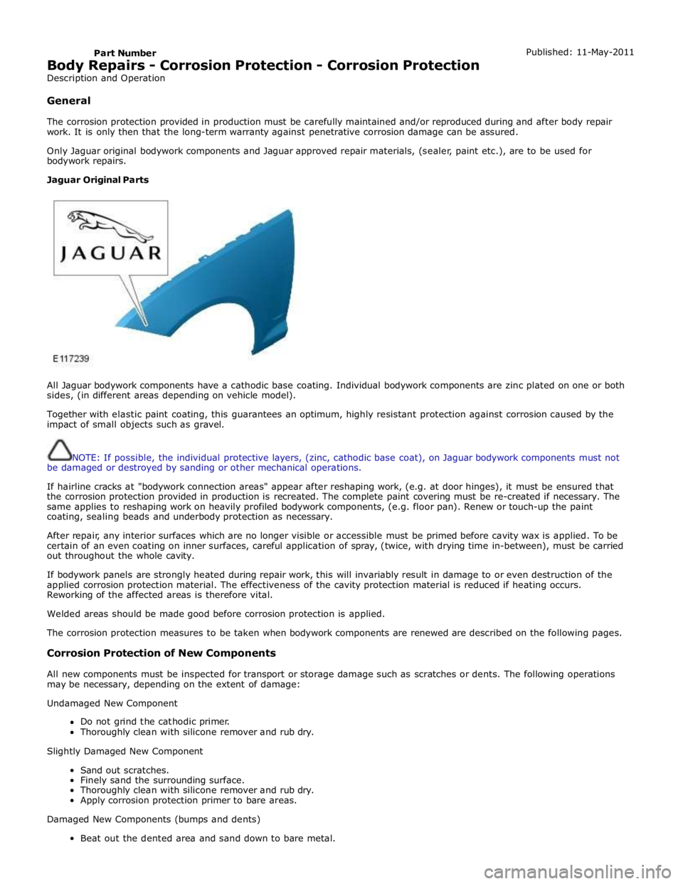
Jaguar Original Parts
All Jaguar bodywork components have a cathodic base coating. Individual bodywork components are zinc plated on one or both
sides, (in different areas depending on vehicle model).
Together with elastic paint coating, this guarantees an optimum, highly resistant protection against corrosion caused by the
impact of small objects such as gravel.
NOTE: If possible, the individual protective layers, (zinc, cathodic base coat), on Jaguar bodywork components must not
be damaged or destroyed by sanding or other mechanical operations.
If hairline cracks at "bodywork connection areas" appear after reshaping work, (e.g. at door hinges), it must be ensured that
the corrosion protection provided in production is recreated. The complete paint covering must be re-created if necessary. The
same applies to reshaping work on heavily profiled bodywork components, (e.g. floor pan). Renew or touch-up the paint
coating, sealing beads and underbody protection as necessary.
After repair, any interior surfaces which are no longer visible or accessible must be primed before cavity wax is applied. To be
certain of an even coating on inner surfaces, careful application of spray, (twice, with drying time in-between), must be carried
out throughout the whole cavity.
If bodywork panels are strongly heated during repair work, this will invariably result in damage to or even destruction of the
applied corrosion protection material. The effectiveness of the cavity protection material is reduced if heating occurs.
Reworking of the affected areas is therefore vital.
Welded areas should be made good before corrosion protection is applied.
The corrosion protection measures to be taken when bodywork components are renewed are described on the following pages.
Corrosion Protection of New Components
All new components must be inspected for transport or storage damage such as scratches or dents. The following operations
may be necessary, depending on the extent of damage:
Undamaged New Component
Do not grind the cathodic primer.
Thoroughly clean with silicone remover and rub dry.
Slightly Damaged New Component
Sand out scratches.
Finely sand the surrounding surface.
Thoroughly clean with silicone remover and rub dry.
Apply corrosion protection primer to bare areas.
Damaged New Components (bumps and dents)
Beat out the dented area and sand down to bare metal.
Page 2731 of 3039
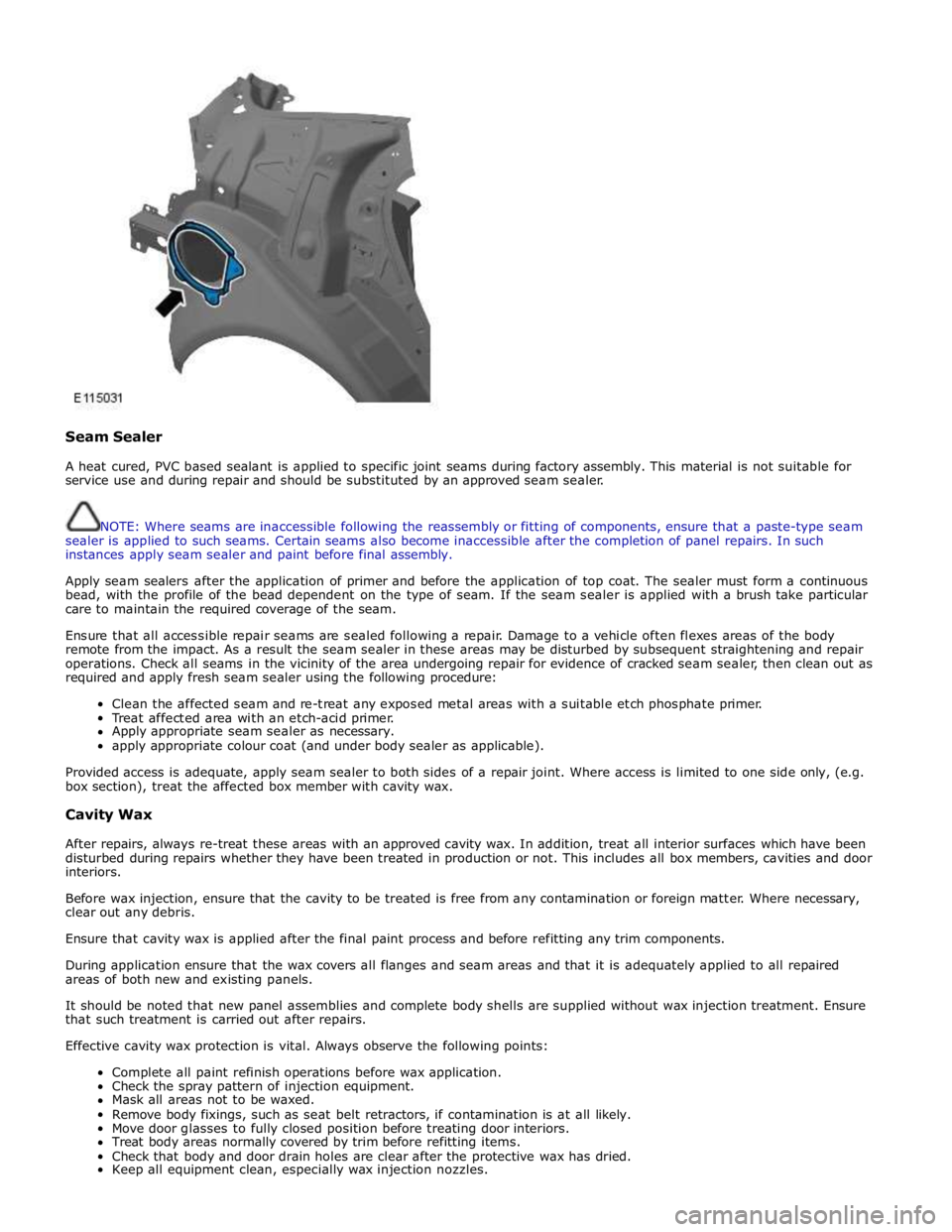
Seam Sealer
A heat cured, PVC based sealant is applied to specific joint seams during factory assembly. This material is not suitable for
service use and during repair and should be substituted by an approved seam sealer.
NOTE: Where seams are inaccessible following the reassembly or fitting of components, ensure that a paste-type seam
sealer is applied to such seams. Certain seams also become inaccessible after the completion of panel repairs. In such
instances apply seam sealer and paint before final assembly.
Apply seam sealers after the application of primer and before the application of top coat. The sealer must form a continuous
bead, with the profile of the bead dependent on the type of seam. If the seam sealer is applied with a brush take particular
care to maintain the required coverage of the seam.
Ensure that all accessible repair seams are sealed following a repair. Damage to a vehicle often flexes areas of the body
remote from the impact. As a result the seam sealer in these areas may be disturbed by subsequent straightening and repair
operations. Check all seams in the vicinity of the area undergoing repair for evidence of cracked seam sealer, then clean out as
required and apply fresh seam sealer using the following procedure:
Clean the affected seam and re-treat any exposed metal areas with a suitable etch phosphate primer.
Treat affected area with an etch-acid primer.
Apply appropriate seam sealer as necessary.
apply appropriate colour coat (and under body sealer as applicable).
Provided access is adequate, apply seam sealer to both sides of a repair joint. Where access is limited to one side only, (e.g.
box section), treat the affected box member with cavity wax.
Cavity Wax
After repairs, always re-treat these areas with an approved cavity wax. In addition, treat all interior surfaces which have been
disturbed during repairs whether they have been treated in production or not. This includes all box members, cavities and door
interiors.
Before wax injection, ensure that the cavity to be treated is free from any contamination or foreign matter. Where necessary,
clear out any debris.
Ensure that cavity wax is applied after the final paint process and before refitting any trim components.
During application ensure that the wax covers all flanges and seam areas and that it is adequately applied to all repaired
areas of both new and existing panels.
It should be noted that new panel assemblies and complete body shells are supplied without wax injection treatment. Ensure
that such treatment is carried out after repairs.
Effective cavity wax protection is vital. Always observe the following points:
Complete all paint refinish operations before wax application.
Check the spray pattern of injection equipment.
Mask all areas not to be waxed.
Remove body fixings, such as seat belt retractors, if contamination is at all likely.
Move door glasses to fully closed position before treating door interiors.
Treat body areas normally covered by trim before refitting items.
Check that body and door drain holes are clear after the protective wax has dried.
Keep all equipment clean, especially wax injection nozzles.