2010 JAGUAR XFR Interior
[x] Cancel search: InteriorPage 2732 of 3039
Part N-umber
Body Repairs - Water Leaks - Water Leaks
Description and Operation
General Published: 11-May-2011
If water leaks occur after bodywork repairs, the cause can be established using the checks described below. A
systematic and logical procedure is required to locate water leaks. Before beginning extensive checks, a thorough visual
inspection must be carried out.
Visual Inspection
- The following characteristics may indicate existing leaks:
- Check the clearance and accurate fit of ancillary components such as the hood, tailgate, liftgate, doors, and so
on.
- Check for correct fit and possible damage to sealing elements such as blanking plugs, rubber door seals, and so
on.
- Check water drain holes for unhindered flow.
Various tests can be used to provide further information on possible leaks:
- Water test
- Washer test
- Road test
- Chalk (powder) test
Practical execution of tests and checks
Water test
NOTE: Never aim a jet of water directly at a rubber seal.
Carry out the water test with a second person present (in the passenger compartment).
Use variable washer nozzles (concentrated water jet to fine spray mist).
Start in the lower section and spray the whole area, working upwards in stages.
Washer test
Further tests can be carried out in the washer system.
Some leaks originate here, or only occur here.
The relevant passenger compartment should be checked using a torch during the wash procedure.
Road test
If no leaks are located during the tests above, road tests should be carried out on wet roads.
Road tests under various conditions:
- At various speeds.
- On various road surfaces (asphalt to cobbles).
- With loaded or unloaded vehicle.
- Driving through puddles (splash water).
Chalk test (powder test)
In this test, the clamping load and the bearing surface of the seal are checked.
Performing the test:
- Dust the door seal with powder or coat with chalk.
- Coat the bearing surface of the seal with a thin film of Vaseline.
- Slowly close the door and open it again.
- Check the width and continuity of the imprint on the door seal.
Other test equipment
Other equipment such as stethoscopes, UV lamps, special mirrors or ultrasound measuring instruments can be used to
locate leaks.
Rectifying the leak using recommended tools, auxiliary equipment and materials
Tools and auxiliary equipment:
- Dry, absorbent cloths
- Variable washer nozzle
- Torch, fluorescent tube
- Mirror
- Compressed air
- Seal lip installer
- Wet/dry vacuum cleaner
- Sealing compound compressor
- Remover for interior trim
- Cutter blade or pocket knife
- Wedge (wood or plastic)
- Hot air blower
- Special mirror for concealed leaks
Page 2735 of 3039
Side windows
In the case of side windows, the same problems can arise as for a windscreen. The same corrective actions must therefore be
used.
Door seal
Diagnosis:
- Water ingress in the lower part of the interior door trim or in the rocker panel area.
Cause:
- The water shield fitted behind the interior door trim exists to drain off water that has entered the door via the
drainage holes, either downwards or outwards. If the water shield seal is damaged or has been fitted incorrectly,
then water can get into the passenger compartment.
- In addition to this, the drainage holes can become clogged with leaves, dirt or excess cavity protection agents.
Water gathers in the door and ingresses into the passenger compartment.
- Check water shield for damage or correct fitting.
- If the water shield needs to be re-bonded, then approved seam sealer should be used.
- Before the water shield is installed, the drainage holes must be checked for unhindered flow.
Door seals
Diagnosis:
- Ingress of water into the rocker panel area
Cause:
- Insufficient clamping load between seal and door.
Corrective action:
NOTE: When adjusting the clamping load, the profile alignment of the relevant components must always be taken
into consideration.
NOTE: Do not realign the flange too far in the direction of the door, as this can reduce the bearing surface of the
seal to the door.
- Check clamping load:
- The easiest way to check the clamping load of a seal to the respective bearing surface is by means of a paper
strip test. This consists of trapping strips of paper at various points between the door and the seal, and fully
closing the door. If it is possible to pull out the paper with no great resistance, then the clamping load is too
low.
- Adjust the clamping load:
- The clamping load is normally adjusted using the striker. When doing so, the edge alignment from the door to
the side panel, or from the front door to the rear door must be taken into account.
- Another setting method is to realign the panel flange for the seal mounting. The clamping load is increased by
moving the flange towards the door.
- Check the bearing surface:
- Apply chalk evenly to the surface of the seal. Evenly coat the bearing surface of the door with Vaseline.
- Close the door fully, the lock must engage. Open the door. The imprint of the chalk (bearing surface) can be
identified in the film of Vaseline.
- The bearing surface should be at least 5mm across at all points.
Other causes:
- The door seal must completely seal the door where it meets the bodywork.
- Water can ingress directly or indirectly into the interior of the vehicle if the seal is damaged at any point.
Corrective action:
- A damaged or worn door seal must always be renewed in full.
- When renewing the seal, the following must be taken into account:
- Always fit the seal first in the area of the narrow radii (corner points).
- Next, secure the seal to the flange evenly by tapping lightly with a rubber hammer. The installed seal must not
be kinked at any point.
NOTE: The prescribed length of a seal must not be shortened.
Other cause:
- The door seal is attached to the welded flange all the way round. If this welded flange is uneven or damaged at
any point (usually in areas with small radii) then this point could be subject to leaks.
- A stretched seal carrier can also cause a leak.
- In both cases, water gets into the vehicle interior under the seal carrier.
Corrective action:
- Align the deformed welded flange using a hammer and anvil block, prevent and, if necessary, repair any paint
damage.
Sliding roof/tilting roof
Diagnosis:
- Ingress of water at sliding roof aperture
Cause:
- The sliding roof/tilting roof is installed in a water trap. The water drains off via the water trap, water drain holes
and drain hoses. The drain hoses lead downwards on both sides via the A-pillar and B-pillar.
- The drain holes or drain hoses can become clogged with leaves, dirt, underbody protection and so on.
Corrective action:
Page 2736 of 3039
NOTE: In the case of a sliding or tilting roof, the external rubber seal and the lock actuator or latch mechanism
must be checked first of all.
- Check the water trap for leaks.
- Check the drain hoses for leaks and for correct connection to the water trap.
- Check the drainage system for unhindered flow, and blow out with compressed air if necessary.
- Check the external seal and the correct adjustment of the sliding roof.
Liftgate
Diagnosis:
- Ingress of water into rear headlining area and luggage area.
Cause:
- The leak problems of the tailgate and liftgate correspond to those of the doors.
- In addition to this, the area to be sealed is much bigger. The routing holes for cables and hoses must also be
sealed.
- The rubber grommets for the routing holes must be checked for damage and correct seating (fully unhooked).
- The mounting points of the liftgate hinges may leak.
Corrective action:
- Check the rubber grommets and renew if necessary.
- Check the hinge mounting points, and re-seal with sealing compound if necessary.
Forced air extraction
Diagnosis:
- Ingress of water into side luggage compartment area
Cause:
- The forced air extraction for the vehicle interior is located in the quarter panel lower extension.
- The rubber flap of the forced air extraction must be able to move freely.
Corrective action:
- Remove the forced air extraction.
- Check the seal area between the bodywork and housing, as well as the rubber flap.
- Renew seal if necessary.
Rear window
Diagnosis:
- Ingress of water into the luggage compartment area
Cause:
- Rear window leaking.
- Check for leak in the same way as for leaking windscreen.
Page 2829 of 3039
(414-01 Battery, Mounting and Cables, General Procedures).
6. Disconnect the generator electrical connectors.
7. Remove the windshield glass.
For additional information, refer to: Windshield Glass (501-11 Glass, Frames and Mechanisms, Removal and Installation).
8. Remove the rear window glass.
For additional information, refer to: Rear Window Glass (501-11 Glass, Frames and Mechanisms, Removal and Installation).
9. Remove the roof opening panel frame.
For additional information, refer to: Roof Opening Panel Frame (501-17 Roof Opening Panel, Removal and Installation).
10. Remove the driver and passenger side front scuff plate trim panels.
For additional information, refer to: Front Scuff Plate Trim Panel (501-05 Interior Trim and Ornamentation, Removal and Installation).
11. Remove the driver and passenger side rear scuff plate trim panels.
For additional information, refer to: Rear Scuff Plate Trim Panel (501-05 Interior Trim and Ornamentation, Removal and Installation).
12. Remove the driver and passenger side air curtain modules.
For additional information, refer to: Side Air Curtain Module (501-20B Supplemental Restraint System, Removal and Installation).
13. Remove the rear seat backrest.
14. Remove the driver and passenger side rear safety belt retractors.
For additional information, refer to: Rear Safety Belt Retractor (501-20A Safety Belt System, Removal and Installation).
15. Remove the rear center safety belt retractor.
For additional information, refer to: Rear Center Safety Belt Retractor (501-20A Safety Belt System, Removal and Installation).
16. Remove the driver and passenger side RF filters.
17. Remove the diversity antenna module.
18. Remove the antenna.
For additional information, refer to: Navigation System Antenna (419-07 Navigation System, Removal and Installation).
19. Release and position the roof wiring harnesses to one side
20. Position the roof opening panel front and rear drain hoses to one side.
21. Remove the driver and passenger side roof mouldings.
22. Drill out the spot welds.
www.JagDocs.com
Page 2836 of 3039
(414-01 Battery, Mounting and Cables, General Procedures).
6. Disconnect the generator electrical connectors.
7. Remove the windshield glass.
For additional information, refer to: Windshield Glass (501-11 Glass, Frames and Mechanisms, Removal and Installation).
8. Remove the rear window glass.
For additional information, refer to: Rear Window Glass (501-11 Glass, Frames and Mechanisms, Removal and Installation).
9. Remove the headliner.
For additional information, refer to: Headliner (501-05 Interior Trim and Ornamentation, Removal and Installation).
10. Remove the driver and passenger side front scuff plate trim panels.
For additional information, refer to: Front Scuff Plate Trim Panel (501-05 Interior Trim and Ornamentation, Removal and Installation).
11. Remove the driver and passenger side rear scuff plate trim panels.
For additional information, refer to: Rear Scuff Plate Trim Panel (501-05 Interior Trim and Ornamentation, Removal and Installation).
12. Remove the driver and passenger side air curtain modules.
For additional information, refer to: Side Air Curtain Module (501-20B Supplemental Restraint System, Removal and Installation).
13. Remove the rear seat backrest.
14. Remove the driver and passenger side rear safety belt retractors.
For additional information, refer to: Rear Safety Belt Retractor (501-20A Safety Belt System, Removal and Installation).
15. Remove the rear center safety belt retractor.
For additional information, refer to: Rear Center Safety Belt Retractor (501-20A Safety Belt System, Removal and Installation).
16. Remove the driver and passenger side RF filters.
17. Remove the diversity antenna module.
18. Remove the antenna.
For additional information, refer to: Navigation System Antenna (419-07 Navigation System, Removal and Installation).
19. Release and position the roof wiring harnesses to one side
20. Remove the driver and passenger side roof mouldings.
21. Drill out the spot welds.
Page 2893 of 3039
Interior Trim and Ornamentation, Removal and Installation).
9. Remove the front safety belt retractor.
For additional information, refer to: Front Safety Belt Retractor (501-20A Safety Belt System, Removal and Installation).
10. Remove the B-pillar side impact sensor.
For additional information, refer to: B-Pillar Side Impact Sensor (501-20B Supplemental Restraint System, Removal and Installation).
11. Remove the C-pillar side impact sensor.
For additional information, refer to: C-Pillar Side Impact Sensor (501-20B Supplemental Restraint System, Removal and Installation).
12. Release and position the floor covering to one side.
13. Release and position the inner rocker panel wiring harness to one side.
14. Remove the rear wheel and tire.
For additional information, refer to: Wheel and Tire (204-04 Wheels and Tires, Removal and Installation).
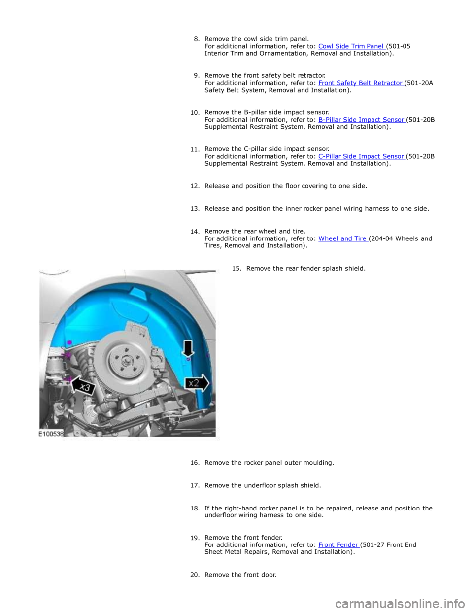
15. Remove the rear fender splash shield.
16.
Remove the rocker panel outer moulding.
17. Remove the underfloor splash shield.
18. If the right-hand rocker panel is to be repaired, release and position the
underfloor wiring harness to one side.
19. Remove the front fender.
For additional information, refer to: Front Fender (501-27 Front End Sheet Metal Repairs, Removal and Installation).
20. Remove the front door.
Page 2903 of 3039
and Installation).
5. Disconnect the generator electrical connectors.
6. Remove the right-hand and left-hand front scuff plate trim panels.
For additional information, refer to: Front Scuff Plate Trim Panel (501-05 Interior Trim and Ornamentation, Removal and Installation).
7. Remove the front and rear door weatherstrips.
8. Remove the right-hand and left-hand rear scuff plate trim panels.
For additional information, refer to: Rear Scuff Plate Trim Panel (501-05 Interior Trim and Ornamentation, Removal and Installation).
9. Remove the headliner.
For additional information, refer to: Headliner (501-05 Interior Trim and Ornamentation, Removal and Installation).
10. Remove the side air curtain module.
For additional information, refer to: Side Air Curtain Module (501-20B Supplemental Restraint System, Removal and Installation).
11. Remove the rear seat cushion.
For additional information, refer to: Rear Seat Cushion (501-10 Seating, Removal and Installation).
12. Remove the rear seat backrest.
13. Release and position the roof wiring harness to one side.
14. Remove the roof moulding.
15. Remove the cowl side trim panel.
For additional information, refer to: Cowl Side Trim Panel (501-05 Interior Trim and Ornamentation, Removal and Installation).
16. Remove the front safety belt retractor.
For additional information, refer to: Front Safety Belt Retractor (501-20A Safety Belt System, Removal and Installation).
17. Remove the B-pillar side impact sensor.
For additional information, refer to: B-Pillar Side Impact Sensor (501-20B Supplemental Restraint System, Removal and Installation).
18. Remove the C-pillar side impact sensor.
For additional information, refer to: C-Pillar Side Impact Sensor (501-20B Supplemental Restraint System, Removal and Installation).
19. Release and position the floor covering to one side.
20. Release and position the inner rocker panel wiring harness to one side.
21. Remove the rear wheel and tire.
For additional information, refer to: Wheel and Tire (204-04 Wheels and
Page 2916 of 3039
Interior Trim and Ornamentation, Removal and Installation).
9. Remove the front safety belt retractor.
For additional information, refer to: Front Safety Belt Retractor (501-20A Safety Belt System, Removal and Installation).
10. Remove the B-pillar side impact sensor.
For additional information, refer to: B-Pillar Side Impact Sensor (501-20B Supplemental Restraint System, Removal and Installation).
11. Remove the C-pillar side impact sensor.
For additional information, refer to: C-Pillar Side Impact Sensor (501-20B Supplemental Restraint System, Removal and Installation).
12. Release and position the floor covering to one side.
13. Release and position the inner rocker panel wiring harness to one side.
14. Remove the rocker panel outer moulding.
15. Remove the underfloor splash shield.
16. If the right-hand rocker panel front section is to be repaired, release and
position the underfloor wiring harness to one side.
17. Remove the front fender.
For additional information, refer to: Front Fender (501-27 Front End Sheet Metal Repairs, Removal and Installation).
18. Remove the front door.
For additional information, refer to: Front Door (501-03 Body Closures, Removal and Installation).
19. Remove the rear door.
For additional information, refer to: Rear Door (501-03 Body Closures, Removal and Installation).
20. Cut the new rocker panel front section from the new rocker panel service
panel.