Page 1980 of 3039

the roof pod and is shared with the DAB (digital audio broadcasting) band L antenna or satellite radio antenna where fitted.
The roof pod is located externally in a central position towards the rear of the roof.
The GPS antenna is designed with 50 ohm output impedance. The navigation computer is fitted with 50 ohm fakra II connectors to ensure compatibility with the antenna. For optimum performance 50 ohm low loss coaxial cable is used between
the antenna and navigation computer.
It is possible for the GPS antenna to lose the signal from the GPS satellites; In hilly or tree lined areas
Built up areas with tall buildings
In multi storey car parks
In garages
In tunnels
On bridges
During heavy rain or thunderstorms
When the signal is lost the navigation computer will continue to give guidance using memory mapped data from the DVD map until the signal is restored.
TMC/VICS FM Antenna
Data messages for both TMC (traffic message channel) and VICS (vehicle information and communication system) are received
through the FM antennas and diversity antenna module located in the heated rear window.
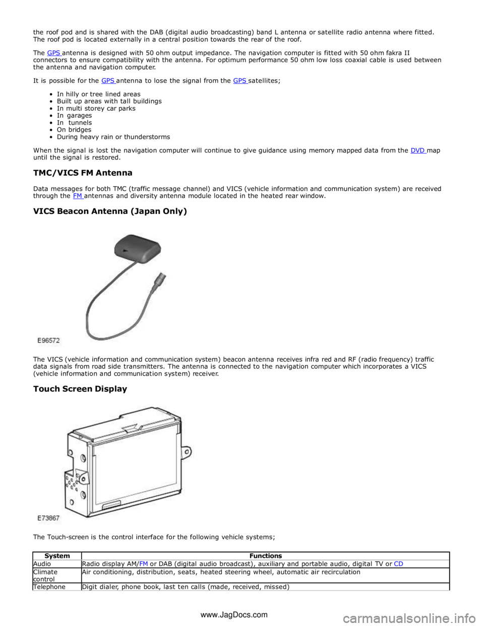
VICS Beacon Antenna (Japan Only)
The VICS (vehicle information and communication system) beacon antenna receives infra red and RF (radio frequency) traffic
data signals from road side transmitters. The antenna is connected to the navigation computer which incorporates a VICS
(vehicle information and communication system) receiver.
Touch Screen Display
The Touch-screen is the control interface for the following vehicle systems;
System Functions Audio Radio display AM/FM or DAB (digital audio broadcast), auxiliary and portable audio, digital TV or CD Climate
control Air conditioning, distribution, seats, heated steering wheel, automatic air recirculation Telephone Digit dialer, phone book, last ten calls (made, received, missed) www.JagDocs.com
Page 1981 of 3039

Navigation Destination, stored locations, navigation setup, route options Vehicle
Security, parking, valet mode, trip computer, clock, brightness, contrast, system settings, vehicle settings, display settings The screen is a touch sensitive 7 inch LCD (liquid crystal display) VGA screen containing 800 x 480 pixels in a 15:9 format. The
screen processes its own video for system operation but receives the navigation graphics from the navigation computer.
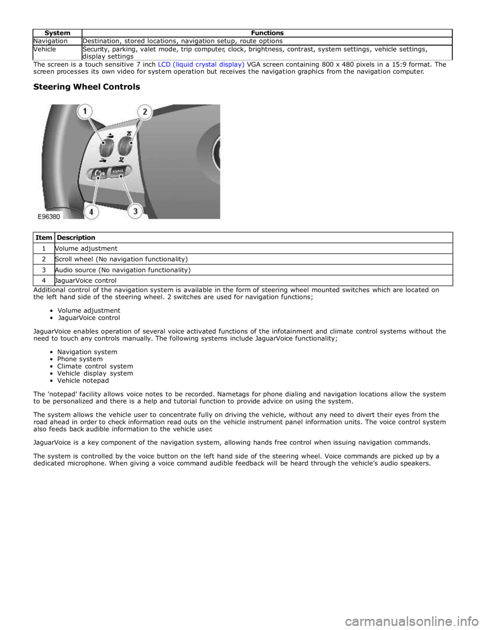
Steering Wheel Controls
Item Description 1 Volume adjustment 2 Scroll wheel (No navigation functionality) 3 Audio source (No navigation functionality) 4 JaguarVoice control Additional control of the navigation system is available in the form of steering wheel mounted switches which are located on
the left hand side of the steering wheel. 2 switches are used for navigation functions;
Volume adjustment
JaguarVoice control
JaguarVoice enables operation of several voice activated functions of the infotainment and climate control systems without the
need to touch any controls manually. The following systems include JaguarVoice functionality;
Navigation system
Phone system
Climate control system
Vehicle display system
Vehicle notepad
The 'notepad' facility allows voice notes to be recorded. Nametags for phone dialing and navigation locations allow the system
to be personalized and there is a help and tutorial function to provide advice on using the system.
The system allows the vehicle user to concentrate fully on driving the vehicle, without any need to divert their eyes from the
road ahead in order to check information read outs on the vehicle instrument panel information units. The voice control system
also feeds back audible information to the vehicle user.
JaguarVoice is a key component of the navigation system, allowing hands free control when issuing navigation commands.
The system is controlled by the voice button on the left hand side of the steering wheel. Voice commands are picked up by a
dedicated microphone. When giving a voice command audible feedback will be heard through the vehicle’s audio speakers.
Page 1991 of 3039
Information and Entertainment System - Audio Unit
Removal and Installation
Removal
NOTE: Removal steps in this procedure may contain installation details. Published: 05-Apr-2013
1. Refer to: Battery Disconnect and Connect (414-01 Battery, Mounting and Cables, General Procedures).
2. Refer to: Audio and Climate Control Assembly (415-01A Information and Entertainment System, Removal and Installation).
3. CAUTION: Protect the surrounding trim to avoid
damage.
4. CAUTION: Cover fiber optic cable connectors to
minimize dust ingress and avoid bending the cables in a
radius of less than 30 mm.
Page 1994 of 3039
Published: 11-May-2011
Information and Entertainment System - Audio and Climate Control Assembly
Removal and Installation
Removal
NOTE: Removal steps in this procedure may contain installation details.
1. Remove both floor console side trim panels.
Refer to: Floor Console Side Trim Panel (501-12 Instrument Panel and Console, Removal and Installation).
Installation
2. Torque: 4 Nm
1. To install, reverse the removal procedure.
Page 1996 of 3039
Published: 11-May-2011
Information and Entertainment System - Information and Entertainment Display
Removal and Installation
Removal
NOTE: Removal steps in this procedure may contain installation details.
1. Refer to: Battery Disconnect and Connect (414-01 Battery, Mounting and Cables, General Procedures).
2. Refer to: Center Registers (412-01 Climate Control, Removal and Installation).
3. Torque: 2 Nm 4. CAUTION: Cover fiber optic cable connectors to
minimize dust ingress and avoid bending the cables in a
radius of less than 30 mm.
Page 2066 of 3039

Published: 11-May-2011
Daytime Running Lamps (DRL) - Daytime Running Lamps (DRL) - System
Operation and Component Description
Description and Operation
CENTRAL JUNCTION BOX (CJB) System Operation
The CJB (central junction box) controls the operation of the DRL (daytime running lamps). The DRL are activated once the CJB detects an ignition on power mode 6 signal.
The CJB also monitors the lighting control switch and the auto lamps feature and overrides the DRL if required.
DAYTIME RUNNING LAMPS - CANADA Component Description
The DRL for this market use full intensity low beam headlamps. The side marker lamps, tail lamps and license plate lamps will be on, but instrument cluster illumination will be off. DRL are active when the following parameters are met:
PARK is not selected on the electronic transmission selector
Electronic Parking Brake (EPB) is off
Power mode 6 (ignition on) detected by the CJB The CJB receives an engine running signal The lighting control switch is in the off or side lamps position.
NOTES:
If the lighting control switch is moved to the headlamp position, DRL are deactivated and normal side lamp and headlamp functionality is operational.
When DRL are active, the headlamp flash function using the left hand steering column multifunction switch will operate normally.
The high beam headlamp function using the left hand steering column stalk switch will be deactivated. When the transmission
is in PARK, DRL are turned off. This is to reduce battery discharge during long periods of engine idling in cold climate conditions. When the electronic transmission selector is moved from the PARK position, normal DRL functionality is restored.
DAYTIME RUNNING LAMPS - DENMARK, HOLLAND, NORWAY, SWEDEN, FINLAND AND POLAND
NOTE: DRL for Poland is on vehicles from 2008MY.
DRL for these markets use full intensity low beam headlamps. Side lamps and license plate lamps will be on, but instrument cluster illumination will be off. DRL are active when the following parameters are met:
Power mode 6 (ignition on) detected by the CJB The CJB receives an engine running signal The lighting control switch is in the off position.
NOTE: When DRL are active, the headlamp flash function using the left hand steering column multifunction switch will operate normally. The high beam headlamp function using the left hand steering column stalk switch will be deactivated.
If the lighting control switch is moved to the side lamp or headlamp positions, DRL are deactivated and normal side lamp and headlamp functionality is operational.
AUTOMATIC HEADLAMPS
On vehicles fitted with the automatic headlamps feature, DRL are overridden if the lighting control switch is in the 'Auto' position and the CJB receives a signal from the rain/light sensor to activate the exterior lights.
When the CJB receives a signal to de-activate the automatic headlamps feature the DRL function is restored providing the parameters for DRL activation are met.
Page 2071 of 3039
N = Medium speed CAN (controller area network) bus 1 Parking aid module 2 RJB 3 Keyless vehicle module 4 RH blind spot monitoring module 5 Driver's seat module 6 Front seat climate control module 7 Information control module 8 ATC module 9 CJB 10 Diagnostic socket 11 Instrument cluster 12 Integrated control panel 13 Front passenger door control module
Page 2166 of 3039
Tire Pressure Monitoring System (TPMS) control module 15 Entertainment system control module 16 Climate seat module COMPONENT LOCATION - HIGH SPEED CAN BUS
Item Description NOTE: LHD vehicle shown 1 ECM - V8 shown 2 Headlamp leveling control module 3 Occupant classification system control module 4 Adaptive damping control module 5 Instrument cluster 6 Electronic transmission selector 7 Electronic Parking Brake (EPB) module 8 RCM (restraints control module)