2010 JAGUAR XFR climate control
[x] Cancel search: climate controlPage 1775 of 3039
Published: 11-May-2011
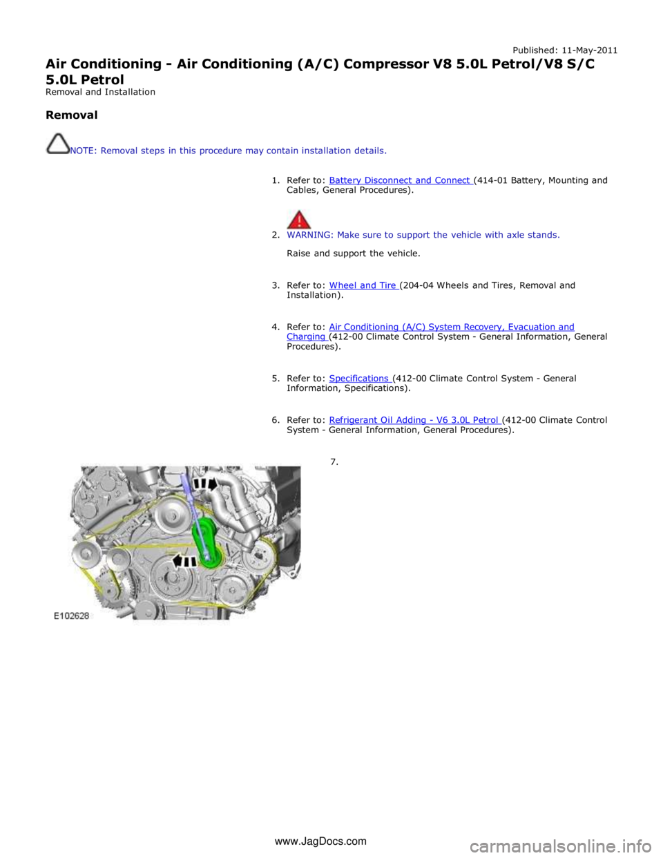
Air Conditioning - Air Conditioning (A/C) Compressor V8 5.0L Petrol/V8 S/C 5.0L Petrol
Removal and Installation
Removal
NOTE: Removal steps in this procedure may contain installation details.
1. Refer to: Battery Disconnect and Connect (414-01 Battery, Mounting and Cables, General Procedures).
2. WARNING: Make sure to support the vehicle with axle stands.
Raise and support the vehicle.
3. Refer to: Wheel and Tire (204-04 Wheels and Tires, Removal and Installation).
4. Refer to: Air Conditioning (A/C) System Recovery, Evacuation and Charging (412-00 Climate Control System - General Information, General Procedures).
5. Refer to: Specifications (412-00 Climate Control System - General Information, Specifications).
6. Refer to: Refrigerant Oil Adding - V6 3.0L Petrol (412-00 Climate Control System - General Information, General Procedures).
7. www.JagDocs.com
Page 1777 of 3039
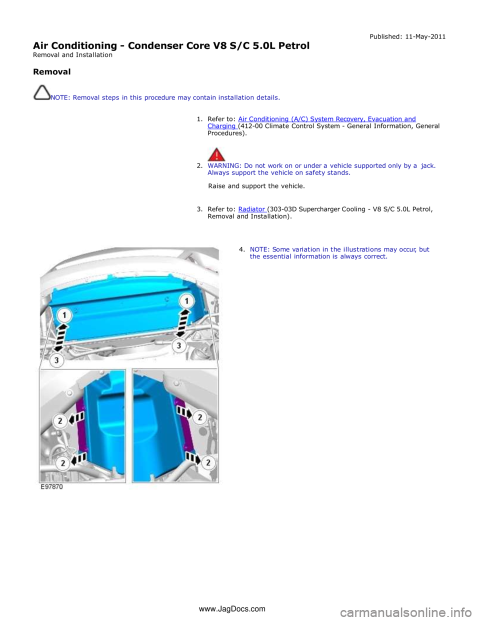
Air Conditioning - Condenser Core V8 S/C 5.0L Petrol
Removal and Installation
Removal
NOTE: Removal steps in this procedure may contain installation details. Published: 11-May-2011
1. Refer to: Air Conditioning (A/C) System Recovery, Evacuation and Charging (412-00 Climate Control System - General Information, General Procedures).
2. WARNING: Do not work on or under a vehicle supported only by a jack.
Always support the vehicle on safety stands.
Raise and support the vehicle.
3. Refer to: Radiator (303-03D Supercharger Cooling - V8 S/C 5.0L Petrol, Removal and Installation).
4. NOTE: Some variation in the illustrations may occur, but
the essential information is always correct. www.JagDocs.com
Page 1779 of 3039
Air Conditioning - Pressure Cutoff Switch
Removal and Installation
Removal
NOTE: Removal steps in this procedure may contain installation details. Published: 11-May-2011
1. For additional information, refer to: Air Conditioning (A/C) System Recovery, Evacuation and Charging (412-00 Climate Control System - General Information, General Procedures).
2. For additional information, refer to: Air Cleaner (303-12, Removal and
Installation).
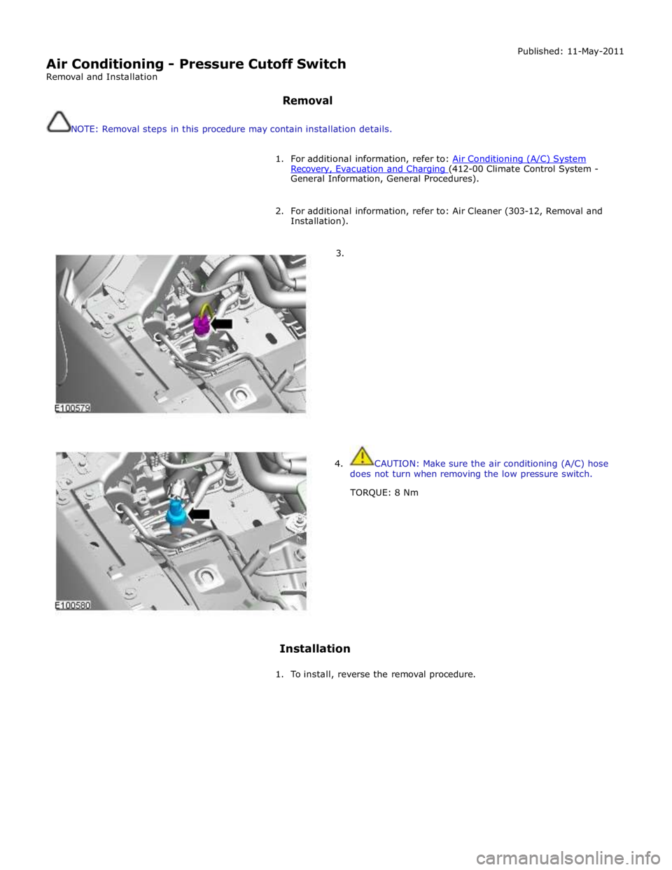
3.
4. CAUTION: Make sure the air conditioning (A/C) hose
does not turn when removing the low pressure switch.
TORQUE: 8 Nm
Installation
1. To install, reverse the removal procedure.
Page 1796 of 3039
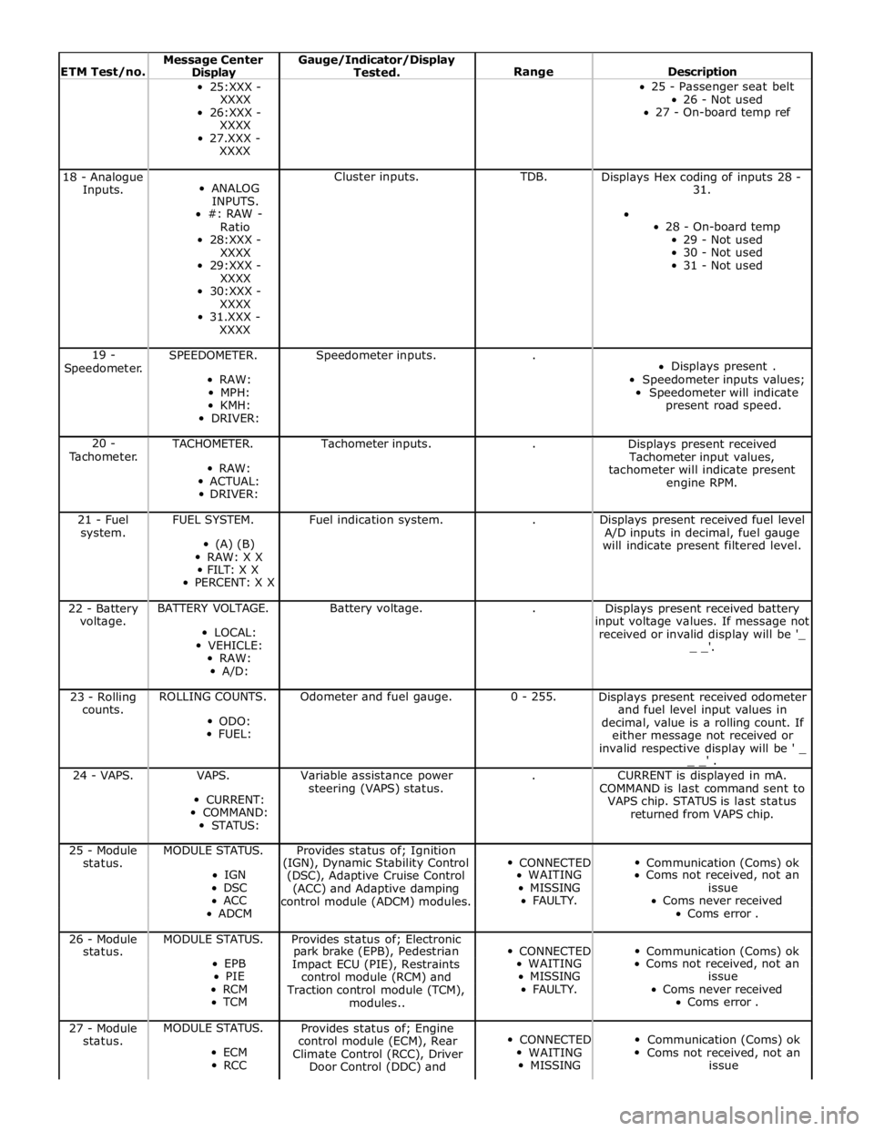
ETM Test/no. Message Center Display Gauge/Indicator/Display
Tested.
Range
Description 25:XXX -
XXXX
26:XXX -
XXXX
27.XXX -
XXXX 25 - Passenger seat belt
26 - Not used
27 - On-board temp ref 18 - Analogue
Inputs.
ANALOG
INPUTS.
#: RAW -
Ratio
28:XXX -
XXXX
29:XXX -
XXXX
30:XXX -
XXXX
31.XXX -
XXXX Cluster inputs. TDB.
Displays Hex coding of inputs 28 -
31.
28 - On-board temp
29 - Not used
30 - Not used
31 - Not used 19 -
Speedometer. SPEEDOMETER.
RAW:
MPH:
KMH:
DRIVER: Speedometer inputs. .
Displays present .
Speedometer inputs values;
Speedometer will indicate
present road speed. 20 -
Tachometer. TACHOMETER.
RAW:
ACTUAL:
DRIVER: Tachometer inputs. .
Displays present received
Tachometer input values,
tachometer will indicate present
engine RPM. 21 - Fuel
system. FUEL SYSTEM.
(A) (B)
RAW: X X
FILT: X X
PERCENT: X X Fuel indication system. .
Displays present received fuel level
A/D inputs in decimal, fuel gauge
will indicate present filtered level. 22 - Battery
voltage. BATTERY VOLTAGE.
LOCAL:
VEHICLE:
RAW:
A/D: Battery voltage. .
Displays present received battery
input voltage values. If message not
received or invalid display will be '_
_ _'. 23 - Rolling
counts. ROLLING COUNTS.
ODO:
FUEL: Odometer and fuel gauge. 0 - 255.
Displays present received odometer
and fuel level input values in
decimal, value is a rolling count. If
either message not received or
invalid respective display will be ' _
_ _' . 24 - VAPS. VAPS.
CURRENT:
COMMAND:
STATUS: Variable assistance power
steering (VAPS) status. .
CURRENT is displayed in mA.
COMMAND is last command sent to
VAPS chip. STATUS is last status
returned from VAPS chip. 25 - Module MODULE STATUS. Provides status of; Ignition
CONNECTED
Communication (Coms) ok status. (IGN), Dynamic Stability Control IGN
(DSC), Adaptive Cruise Control WAITING Coms not received, not an DSC
(ACC) and Adaptive damping MISSING issue ACC
control module (ADCM) modules. FAULTY. Coms never received ADCM Coms error . 26 - Module MODULE STATUS. Provides status of; Electronic
CONNECTED
Communication (Coms) ok status. park brake (EPB), Pedestrian EPB
Impact ECU (PIE), Restraints WAITING Coms not received, not an PIE
control module (RCM) and MISSING issue RCM
Traction control module (TCM), FAULTY. Coms never received TCM
modules.. Coms error . 27 - Module
status. MODULE STATUS.
ECM
RCC Provides status of; Engine
control module (ECM), Rear
Climate Control (RCC), Driver
Door Control (DDC) and
CONNECTED
WAITING
MISSING
Communication (Coms) ok
Coms not received, not an
issue
Page 1805 of 3039

DTC Description Possible Cause Action U013900
Lost
Communication
with Suspension
Control Module 'B'
Loss of CAN communication
with adaptive damping module Carry out any pinpoint tests associated with this DTC using
the manufacturer approved diagnostic system. Check
adaptive damping module for DTCs and refer to the relevant
DTC Index U014000
Lost
Communication
With Body
Control Module
Loss of CAN communication
with CJB Carry out any pinpoint tests associated with this DTC using
the manufacturer approved diagnostic system. Check CJB for
DTCs and refer to the relevant DTC Index U014200
Lost
Communication
With Body
Control Module
"B"
Loss of CAN communication
with RJB Carry out any pinpoint tests associated with this DTC using
the manufacturer approved diagnostic system. Check RJB for
DTCs and refer to the relevant DTC Index U015100
Lost
Communication
With Restraints
Control Module
Loss of CAN communication
with RCM Carry out any pinpoint tests associated with this DTC using
the manufacturer approved diagnostic system. Check RCM for
DTCs and refer to the relevant DTC Index U015600
Lost
Communication
with Information
Centre 'A'
Loss of CAN communication
with information and
entertainment control module Carry out any pinpoint tests associated with this DTC using
the manufacturer approved diagnostic system. Check
information and entertainment control module for DTCs and
refer to the relevant DTC Index U016400
Lost
Communication
with HVAC
Control Module
Loss of CAN communication
with climate control module Carry out any pinpoint tests associated with this DTC using
the manufacturer approved diagnostic system. Check climate
control module for DTCs and refer to the relevant DTC Index U019900
Lost
Communication
with Door Control
Module 'A'
Loss of CAN communication
with driver door module (DDM) Carry out any pinpoint tests associated with this DTC using
the manufacturer approved diagnostic system. Check DDM for
DTCs and refer to the relevant DTC Index U020000
Lost
Communication
with Door Control
Module 'B'
Loss of CAN communication
with passenger door module
(PDM) Carry out any pinpoint tests associated with this DTC using
the manufacturer approved diagnostic system. Check PDM for
DTCs and refer to the relevant DTC Index U020800
Lost
Communication
with Seat Control
Module 'A'
Loss of CAN communication
with driver seat module (DSM) Carry out any pinpoint tests associated with this DTC using
the manufacturer approved diagnostic system. Check DSM for
DTCs and refer to the relevant DTC Index U021400
Lost
Communication
with Remote
Function
Actuation
Loss of CAN communication
with keyless vehicle module
(KVM) Carry out any pinpoint tests associated with this DTC using
the manufacturer approved diagnostic system. Check KVM for
DTCs and refer to the relevant DTC Index U024100
Lost
Communication
with Headlamp
Control Module 'A'
Loss of CAN communication
with headlamp control module Carry out any pinpoint tests associated with this DTC using
the manufacturer approved diagnostic system. Check
headlamp control module for DTCs and refer to the relevant
DTC Index U025000
Lost
Communication
with Impact
Classification System Module
Loss of CAN communication
with pedestrian protection
module Carry out any pinpoint tests associated with this DTC using
the manufacturer approved diagnostic system. Check
pedestrian protection module for DTCs and refer to the
relevant DTC Index U025600
Lost
Communication
with Front
Controls Interface
Module 'A'
Loss of CAN communication
with integrated control panel Carry out any pinpoint tests associated with this DTC using
the manufacturer approved diagnostic system. Check
integrated control panel for DTCs and refer to the relevant
DTC Index U030000
Internal Control
Module Software
Incompatibility
Invalid configuration message
is received Re-configure the RJB using the manufacturer approved
diagnostic system. Clear the DTC and retest. If the DTC is
still logged suspect the instrument cluster, refer to the new
module/component installation note at the top of the DTC
Index U040268
Invalid data
received from
TCM
Algorithm based failures -
events information Check TCM for DTCs and refer to the relevant DTC Index U200411
Auxiliary Switch
Pack
Auxiliary switch signal circuit -
short to ground Refer to the electrical circuit diagrams and check auxiliary
switch signal circuit for short to ground U200415
Auxiliary Switch
Pack
Auxiliary switch signal circuit -
short to power, open circuit Carry out any pinpoint tests associated with this DTC using
the manufacturer approved diagnostic system. Refer to the
electrical circuit diagrams and check auxiliary switch signal
circuit for short to power, open circuit
Page 1879 of 3039

The dual battery system comprises the following components:
Dual Battery Module (DBM).
Dual Battery Junction Box (DBJB).
Gateway Module (GWM).
Primary battery.
Secondary battery.
The GWM hosts most of the software required to control the dual battery system and components. The GWM monitors the
components and can store fault related DTC's.
The GWM also controls the charging system software in conjunction with the ECM, RJB, CJB and ABS (anti-lock brake system) control module via the high speed and medium speed CAN (controller area network) bus. The GWM software will monitor the
status of the stop/start system and determine when a stop/start event can occur. It can also intervene to maintain vehicle
systems by keeping the engine running or initiating a restart due to, for example, climate control system requirements or
request for restart from the ECM. A brake pressure signal is received from the ABS control module which will indicate to the
GWM that an engine restart is required from driver operation of the foot brake.
The GWM contains the intelligent power management system and the BMS software. Monitoring of the primary battery
condition for stop/start is controlled by the GWM and the BMS control module.
Page 1949 of 3039
systems.
A typical example of information transfer is vehicle speed information from the ABS (anti-lock brake system) module used to
control the automatic volume control function. The vehicle speed information from the ABS module is sent on the high speed
CAN network and collected by the instrument panel gateway. The signal is passed to the medium speed CAN network and onto the ICM gateway. The ICM calculates the volume adjustment required. The corrected audio volume level signal is sent on the
MOST network to the IAM or Power amplifier (dependant on vehicle equipment level) for output to the speaker system.
AUDIO SYSTEM USER CONTROLS
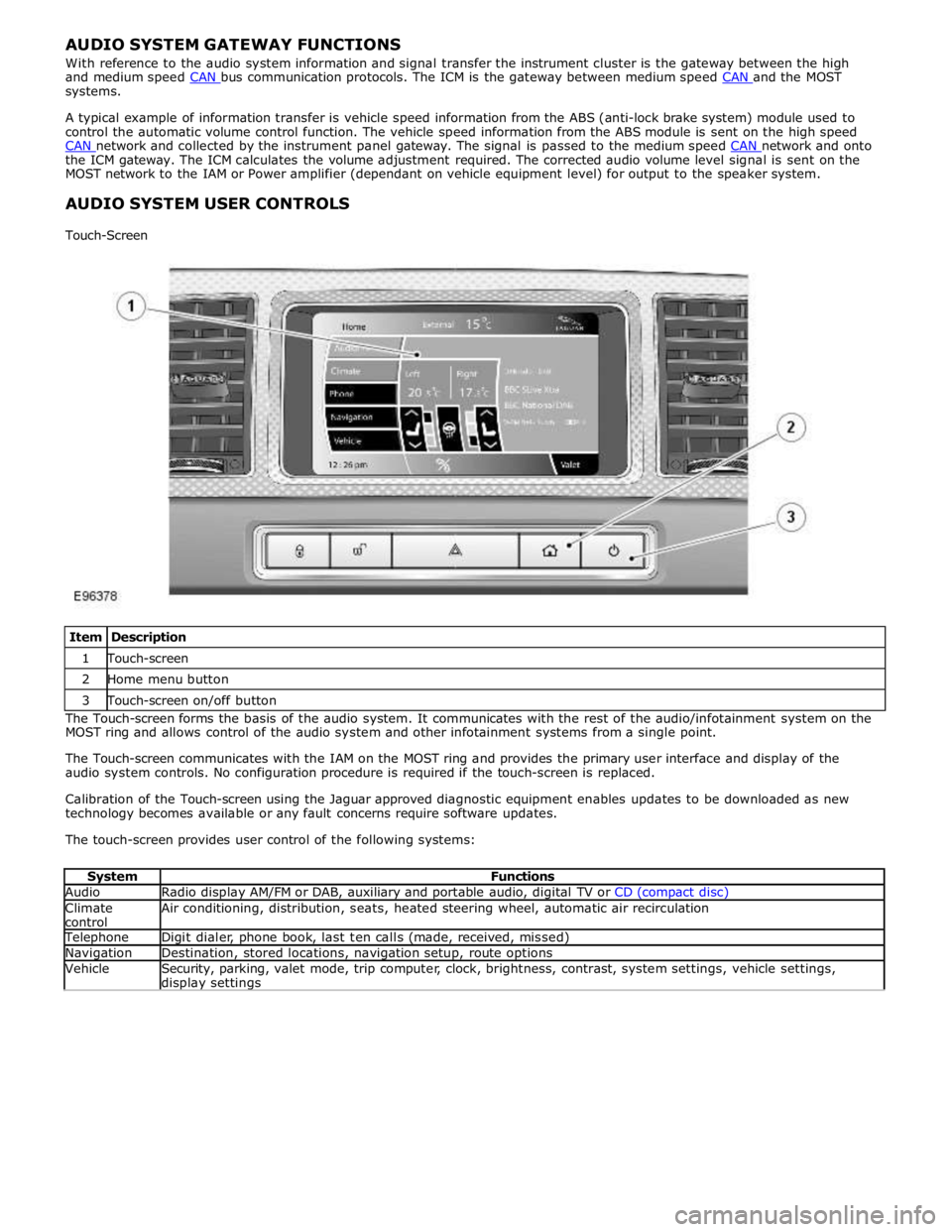
Touch-Screen
Item Description 1 Touch-screen 2 Home menu button 3 Touch-screen on/off button The Touch-screen forms the basis of the audio system. It communicates with the rest of the audio/infotainment system on the
MOST ring and allows control of the audio system and other infotainment systems from a single point.
The Touch-screen communicates with the IAM on the MOST ring and provides the primary user interface and display of the
audio system controls. No configuration procedure is required if the touch-screen is replaced.
Calibration of the Touch-screen using the Jaguar approved diagnostic equipment enables updates to be downloaded as new
technology becomes available or any fault concerns require software updates.
The touch-screen provides user control of the following systems:
System Functions Audio Radio display AM/FM or DAB, auxiliary and portable audio, digital TV or CD (compact disc) Climate
control Air conditioning, distribution, seats, heated steering wheel, automatic air recirculation Telephone Digit dialer, phone book, last ten calls (made, received, missed) Navigation Destination, stored locations, navigation setup, route options Vehicle
Security, parking, valet mode, trip computer, clock, brightness, contrast, system settings, vehicle settings, display settings
Page 1953 of 3039
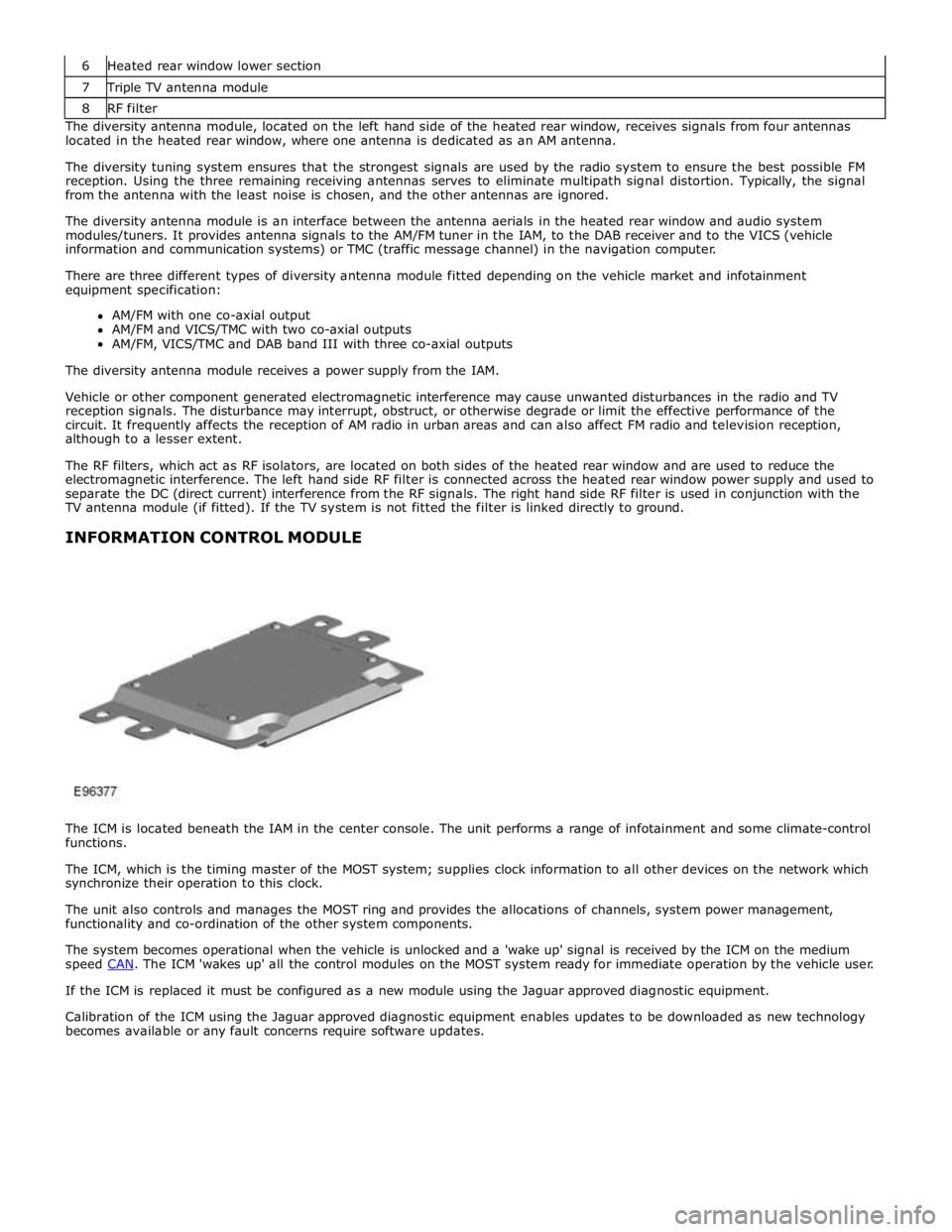
7 Triple TV antenna module 8 RF filter The diversity antenna module, located on the left hand side of the heated rear window, receives signals from four antennas
located in the heated rear window, where one antenna is dedicated as an AM antenna.
The diversity tuning system ensures that the strongest signals are used by the radio system to ensure the best possible FM
reception. Using the three remaining receiving antennas serves to eliminate multipath signal distortion. Typically, the signal
from the antenna with the least noise is chosen, and the other antennas are ignored.
The diversity antenna module is an interface between the antenna aerials in the heated rear window and audio system
modules/tuners. It provides antenna signals to the AM/FM tuner in the IAM, to the DAB receiver and to the VICS (vehicle
information and communication systems) or TMC (traffic message channel) in the navigation computer.
There are three different types of diversity antenna module fitted depending on the vehicle market and infotainment
equipment specification:
AM/FM with one co-axial output
AM/FM and VICS/TMC with two co-axial outputs
AM/FM, VICS/TMC and DAB band III with three co-axial outputs
The diversity antenna module receives a power supply from the IAM.
Vehicle or other component generated electromagnetic interference may cause unwanted disturbances in the radio and TV
reception signals. The disturbance may interrupt, obstruct, or otherwise degrade or limit the effective performance of the
circuit. It frequently affects the reception of AM radio in urban areas and can also affect FM radio and television reception,
although to a lesser extent.
The RF filters, which act as RF isolators, are located on both sides of the heated rear window and are used to reduce the
electromagnetic interference. The left hand side RF filter is connected across the heated rear window power supply and used to
separate the DC (direct current) interference from the RF signals. The right hand side RF filter is used in conjunction with the
TV antenna module (if fitted). If the TV system is not fitted the filter is linked directly to ground.
INFORMATION CONTROL MODULE
The ICM is located beneath the IAM in the center console. The unit performs a range of infotainment and some climate-control
functions.
The ICM, which is the timing master of the MOST system; supplies clock information to all other devices on the network which
synchronize their operation to this clock.
The unit also controls and manages the MOST ring and provides the allocations of channels, system power management,
functionality and co-ordination of the other system components.
The system becomes operational when the vehicle is unlocked and a 'wake up' signal is received by the ICM on the medium
speed CAN. The ICM 'wakes up' all the control modules on the MOST system ready for immediate operation by the vehicle user. If the ICM is replaced it must be configured as a new module using the Jaguar approved diagnostic equipment.
Calibration of the ICM using the Jaguar approved diagnostic equipment enables updates to be downloaded as new technology
becomes available or any fault concerns require software updates.