2010 JAGUAR XFR Cooling
[x] Cancel search: CoolingPage 1524 of 3039
Published: 11-May-2011
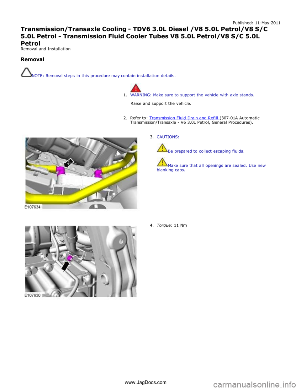
Transmission/Transaxle Cooling - TDV6 3.0L Diesel /V8 5.0L Petrol/V8 S/C 5.0L Petrol - Transmission Fluid Cooler Tubes V8 5.0L Petrol/V8 S/C 5.0L
Petrol
Removal and Installation
Removal
NOTE: Removal steps in this procedure may contain installation details.
1. WARNING: Make sure to support the vehicle with axle stands.
Raise and support the vehicle.
2. Refer to: Transmission Fluid Drain and Refill (307-01A Automatic Transmission/Transaxle - V6 3.0L Petrol, General Procedures).
3. CAUTIONS:
Be prepared to collect escaping fluids.
Make sure that all openings are sealed. Use new
blanking caps.
4. Torque: 11 Nm www.JagDocs.com
Page 1664 of 3039

Published: 11-Jul-2014
Climate Control System - General Information - Climate Control System
Diagnosis and Testing
Principles of Operation
For a detailed description of the Climate Control System, refer to the relevant Description and Operation sections in the
Workshop Manual. REFER to:
Air Distribution and Filtering (412-01 Climate Control, Description and Operation), Air Distribution and Filtering (412-01 Climate Control, Description and Operation), Air Distribution and Filtering (412-01 Climate Control, Description and Operation), Heating and Ventilation (412-01 Climate Control, Description and Operation), Heating and Ventilation (412-01 Climate Control, Description and Operation), Heating and Ventilation (412-01 Climate Control, Description and Operation), Air Conditioning (412-01 Climate Control, Description and Operation), Air Conditioning (412-01 Climate Control, Description and Operation), Air Conditioning (412-01 Climate Control, Description and Operation), Control Components (412-01 Climate Control, Description and Operation), Control Components (412-01 Climate Control, Description and Operation), Control Components (412-01 Climate Control, Description and Operation), Electric Booster Heater (412-02 Auxiliary Climate Control, Description and Operation), Electric Booster Heater (412-02 Auxiliary Climate Control, Description and Operation), Electric Booster Heater (412-02 Auxiliary Climate Control, Description and Operation).
Inspection and Verification
WARNING: Servicing must be carried out by personnel familiar with both vehicle system and the charging and testing
equipment. All operations must be carried out in a well ventilated area away from open flame and heat sources.
CAUTION: Diagnosis by substitution from a donor vehicle is NOT acceptable. Substitution of control modules does not
guarantee confirmation of a fault, and may also cause additional faults in the vehicle being tested and/or the donor vehicle.
NOTE: Check and rectify basic faults before beginning diagnostic routines involving pinpoint tests.
1. Verify the customer concern
2. Visually inspect for obvious signs of damage and system integrity
Visual Inspection
Mechanical Electrical
Coolant level
Hose(s)
Coolant pump
Control flap(s)
Duct(s)
Vent(s)
Cabin air filter
Drive belt
Air conditioning compressor
Thermostatic expansion valve
Evaporator
Receiver drier
Air conditioning condenser
Refrigerant pipes Auxiliary
drive belt
Fuel fired booster heater
Fuel fired booster heater fuel pump
Fuel fired booster heater fuel pipes
Fuse(s)
Wiring harness
Electrical connectors
Blower
Air conditioning compressor
Electric cooling fan
Automatic Temperature Control Module (ATCM)
Refrigerant pressure sensor
3. If an obvious cause for an observed or reported concern is found, correct the cause (if possible) before proceeding to
the next step
4. If the cause is not visually evident, verify the symptom and refer to the Symptom Chart, alternatively check for
Diagnostic Trouble Codes (DTCs) and refer to the DTC Index
5. Check DDW for open campaigns. Refer to the corresponding bulletins and SSMs which may be valid for the specific
customer complaint and carry out the recommendations as required
Page 1665 of 3039
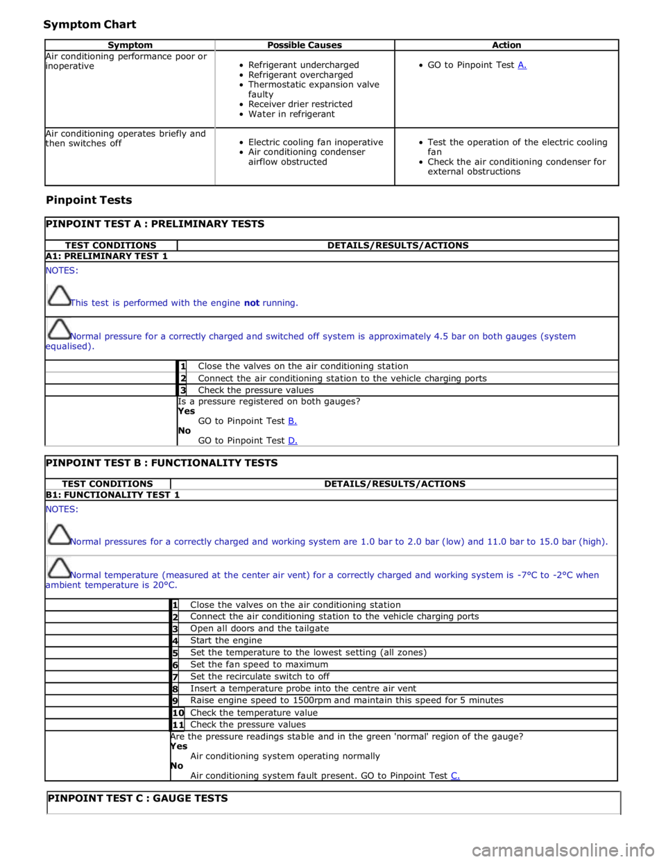
Symptom Chart
Symptom Possible Causes Action Air conditioning performance poor or
inoperative
Refrigerant undercharged
Refrigerant overcharged
Thermostatic expansion valve
faulty
Receiver drier restricted
Water in refrigerant
GO to Pinpoint Test A. Air conditioning operates briefly and
then switches off
Electric cooling fan inoperative
Air conditioning condenser
airflow obstructed
Test the operation of the electric cooling
fan
Check the air conditioning condenser for
external obstructions Pinpoint Tests
PINPOINT TEST A : PRELIMINARY TESTS TEST CONDITIONS DETAILS/RESULTS/ACTIONS A1: PRELIMINARY TEST 1 NOTES:
This test is performed with the engine not running.
Normal pressure for a correctly charged and switched off system is approximately 4.5 bar on both gauges (system
equalised). 1 Close the valves on the air conditioning station 2 Connect the air conditioning station to the vehicle charging ports 3 Check the pressure values Is a pressure registered on both gauges? Yes
GO to Pinpoint Test B. No
GO to Pinpoint Test D.
PINPOINT TEST B : FUNCTIONALITY TESTS TEST CONDITIONS DETAILS/RESULTS/ACTIONS B1: FUNCTIONALITY TEST 1 NOTES:
Normal pressures for a correctly charged and working system are 1.0 bar to 2.0 bar (low) and 11.0 bar to 15.0 bar (high).
Normal temperature (measured at the center air vent) for a correctly charged and working system is -7°C to -2°C when
ambient temperature is 20°C. 1 Close the valves on the air conditioning station 2 Connect the air conditioning station to the vehicle charging ports 3 Open all doors and the tailgate 4 Start the engine 5 Set the temperature to the lowest setting (all zones) 6 Set the fan speed to maximum 7 Set the recirculate switch to off 8 Insert a temperature probe into the centre air vent 9 Raise engine speed to 1500rpm and maintain this speed for 5 minutes 10 Check the temperature value 11 Check the pressure values Are the pressure readings stable and in the green 'normal' region of the gauge? Yes
Air conditioning system operating normally No
Air conditioning system fault present. GO to Pinpoint Test C.
PINPOINT TEST C : GAUGE TESTS
Page 1693 of 3039
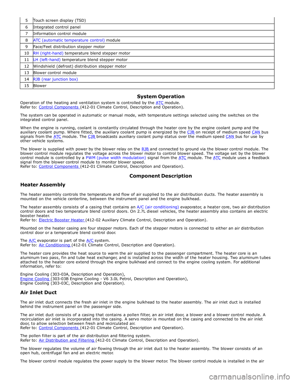
Touch screen display (TSD) 6 Integrated control panel 7 Information control module 8 ATC (automatic temperature control) module 9 Face/Feet distribution stepper motor 10 RH (right-hand) temperature blend stepper motor 11 LH (left-hand) temperature blend stepper motor 12 Windshield (defrost) distribution stepper motor 13 Blower control module 14 RJB (rear junction box) 15 Blower
System Operation
Operation of the heating and ventilation system is controlled by the ATC module. Refer to: Control Components (412-01 Climate Control, Description and Operation).
The system can be operated in automatic or manual mode, with temperature settings selected using the switches on the
integrated control panel.
When the engine is running, coolant is constantly circulated through the heater core by the engine coolant pump and the
auxiliary coolant pump. Where fitted, the auxiliary coolant pump is energized by the CJB on receipt of medium speed CAN bus signals from the ATC module. The CJB broadcasts auxiliary coolant pump status over the medium speed CAN bus for use by other vehicle systems.
The blower is supplied with power by the blower relay on the RJB and connected to ground via the blower control module. The blower control module regulates the voltage across the blower motor to control blower speed. The voltage set by the blower
control module is controlled by a PWM (pulse width modulation) signal from the ATC module. The ATC module uses a feedback signal from the blower control module to monitor blower speed.
Refer to: Control Components (412-01 Climate Control, Description and Operation).
Heater Assembly Component Description
The heater assembly controls the temperature and flow of air supplied to the air distribution ducts. The heater assembly is
mounted on the vehicle centerline, between the instrument panel and the engine bulkhead.
The heater assembly consists of a casing that contains an A/C (air conditioning) evaporator, a heater core, two air distribution
control doors and two temperature blend control doors. On 2.7L diesel vehicles, the heater assembly also contains an electric
booster heater.
Refer to: Electric Booster Heater (412-02 Auxiliary Climate Control, Description and Operation).
Mounted on the heater casing are four stepper motors. Each of the stepper motors is connected to either an air distribution
control door or a temperature blend control door.
The A/C evaporator is part of the A/C system. Refer to: Air Conditioning (412-01 Climate Control, Description and Operation).
The heater core provides the heat source to warm the air supplied to the passenger compartment. The heater core is an
aluminum two pass, fin and tube heat exchanger, and is installed across the width of the heater housing. Two aluminum tubes
attached to the heater core extend through the engine bulkhead and connect to the engine cooling system. For additional
information, refer to:
Engine Cooling (303-03A, Description and Operation),
Engine Cooling (303-03B Engine Cooling - V6 3.0L Petrol, Description and Operation), Engine Cooling (303-03C, Description and Operation).
Air Inlet Duct
The air inlet duct connects the fresh air inlet in the engine bulkhead to the heater assembly. The air inlet duct is installed
behind the instrument panel on the passenger side.
The air inlet duct consists of a casing that contains a pollen filter, an air inlet door, a blower and a blower control module. A
recirculation air inlet is incorporated into the casing. A servo motor is mounted on the casing and connected to the air inlet
door, to allow selection between fresh and recirculated air.
Refer to: Control Components (412-01 Climate Control, Description and Operation). The pollen filter is part of the air distribution and filtering system.
Refer to: Air Distribution and Filtering (412-01 Climate Control, Description and Operation).
The blower regulates the volume of air flowing through the air inlet duct to the heater assembly. The blower consists of an
open hub, centrifugal fan and an electric motor.
The blower control module regulates the power supply to the blower motor. The blower control module is installed in the air
Page 1699 of 3039
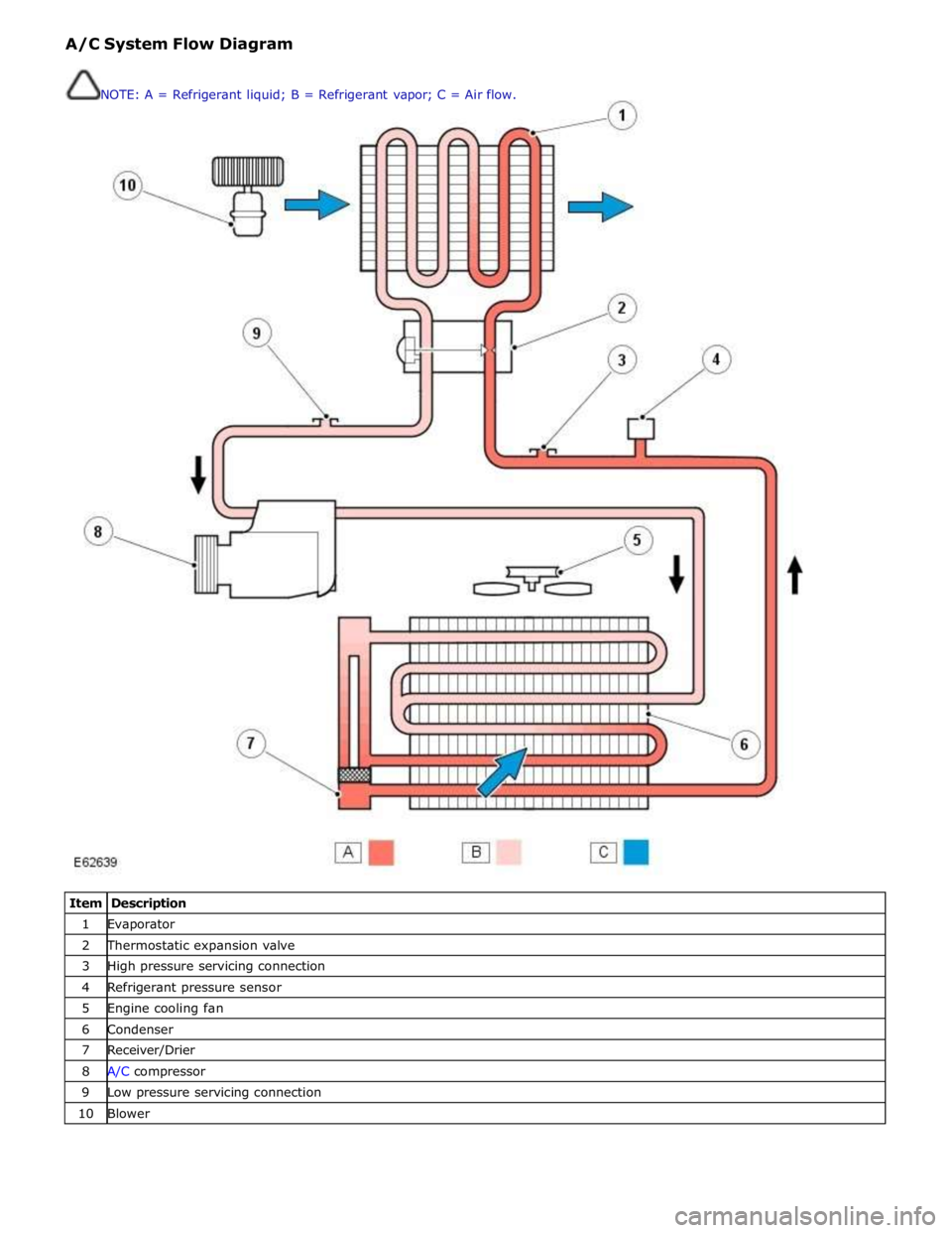
1 Evaporator 2 Thermostatic expansion valve 3 High pressure servicing connection 4 Refrigerant pressure sensor 5 Engine cooling fan 6 Condenser 7 Receiver/Drier 8 A/C compressor 9 Low pressure servicing connection 10 Blower NOTE: A = Refrigerant liquid; B = Refrigerant vapor; C = Air flow.
Page 1701 of 3039
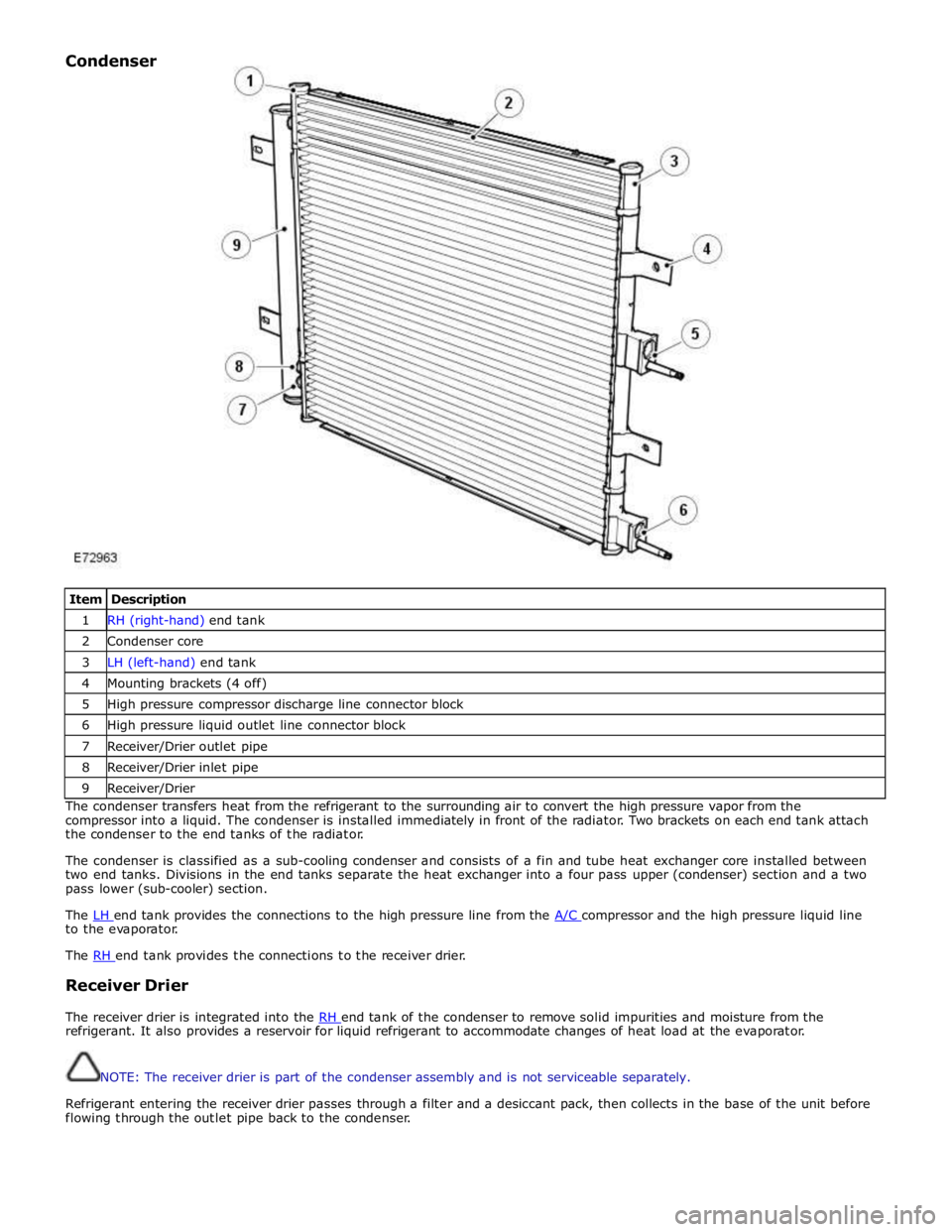
Item Description 1 RH (right-hand) end tank 2 Condenser core 3 LH (left-hand) end tank 4 Mounting brackets (4 off) 5 High pressure compressor discharge line connector block 6 High pressure liquid outlet line connector block 7 Receiver/Drier outlet pipe 8 Receiver/Drier inlet pipe 9 Receiver/Drier The condenser transfers heat from the refrigerant to the surrounding air to convert the high pressure vapor from the
compressor into a liquid. The condenser is installed immediately in front of the radiator. Two brackets on each end tank attach
the condenser to the end tanks of the radiator.
The condenser is classified as a sub-cooling condenser and consists of a fin and tube heat exchanger core installed between
two end tanks. Divisions in the end tanks separate the heat exchanger into a four pass upper (condenser) section and a two
pass lower (sub-cooler) section.
The LH end tank provides the connections to the high pressure line from the A/C compressor and the high pressure liquid line to the evaporator.
The RH end tank provides the connections to the receiver drier.
Receiver Drier
The receiver drier is integrated into the RH end tank of the condenser to remove solid impurities and moisture from the refrigerant. It also provides a reservoir for liquid refrigerant to accommodate changes of heat load at the evaporator.
NOTE: The receiver drier is part of the condenser assembly and is not serviceable separately.
Refrigerant entering the receiver drier passes through a filter and a desiccant pack, then collects in the base of the unit before
flowing through the outlet pipe back to the condenser. Condenser
Page 1709 of 3039
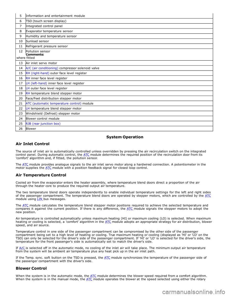
6 TSD (touch screen display) 7 Integrated control panel 8 Evaporator temperature sensor 9 Humidity and temperature sensor 10 Sunload sensor 11 Refrigerant pressure sensor 12 Pollution sensor Comments:
where fitted 13 Air inlet servo motor 14 A/C (air conditioning) compressor solenoid valve 15 RH (right-hand) outer face level register 16 RH inner face level register 17 LH (left-hand) inner face level register 18 LH outer face level register 19 RH temperature blend stepper motor 20 Face/Feet distribution stepper motor 21 ATC (automatic temperature control) module 22 LH temperature blend stepper motor 23 Windshield (Defrost) stepper motor 24 Blower control module 25 RJB (rear junction box) 26 Blower
Air Inlet Control System Operation
The source of inlet air is automatically controlled unless overridden by pressing the air recirculation switch on the integrated
control panel. During automatic control, the ATC module determines the required position of the recirculation door from its 'comfort' algorithm and, if fitted, the pollution sensor.
The ATC module provides analogue signals to the air inlet servo motor along a hardwired connection. A potentiometer in the motor supplies the ATC module with a position feedback signal for closed loop control.
Air Temperature Control
Cooled air from the evaporator enters the heater assembly, where temperature blend doors direct a proportion of the air
through the heater core to produce the required output air temperature.
The two temperature blend doors operate independently to enable individual temperature settings for the left and right sides
of the passenger compartment. The temperature blend doors are operated by stepper motors, which are controlled by the ATC module using LIN bus messages.
The ATC module calculates the temperature blend stepper motor positions required to achieve the selected temperature and compares it against the current position. If there is any difference, the ATC module signals the stepper motors to adopt the new position.
Air temperature is controlled automatically unless maximum heating (HI) or maximum cooling (LO) is selected. When maximum
heating or cooling is selected, a 'comfort' algorithm in the ATC module adopts an appropriate strategy for air distribution, blower speed, and air source.
Temperature control in one side of the passenger compartment can be compromised by the other side of the passenger
compartment being set to a high level of heating or cooling. True maximum heating or cooling (displayed as 'HI' or 'LO' on the
TSD) can only be selected for the driver's side of the passenger compartment. If 'HI' or 'LO' is selected for the driver's side, the
temperature for the front passenger's side is automatically set to match the driver's side.
If A/C is selected off in the automatic mode, no cooling of the inlet air will take place. The minimum output air temperature from the system will be ambient air temperature plus any heat pick up in the air inlet path.
If the Temp. sync. soft button on the TSD is pressed, the ATC module synchronizes the temperature of the passenger side of the passenger compartment with the driver's side.
Blower Control
When the system is in the automatic mode, the ATC module determines the blower speed required from a comfort algorithm. When the system is in the manual mode, the ATC module operates the blower at the speed selected using either the rotary
Page 1710 of 3039
control switch on the integrated control panel or the + and - soft buttons on the touch screen display (TSD). The ATC module also adjusts blower speed to compensate for the ram effect on inlet air produced by forward movement of the vehicle. As
vehicle speed and ram effect increases, blower motor speed is reduced, and vice versa.
Air Distribution Control
Two air distribution doors are used to direct air into the passenger compartment. The doors are operated by stepper motors,
which are controlled by the ATC module using LIN bus messages.
When the A/C system is in automatic mode, the ATC module automatically controls air distribution into the passenger compartment in line with its 'comfort' algorithm. Automatic control is overridden if any of the TSD air distribution soft buttons
are selected. Air distribution in the passenger compartment will remain as selected until the 'Auto' switch is pressed or a
different manual selection is made.
A/C Compressor Control
When A/C is selected the ATC module maintains the evaporator at an operating temperature that varies with the passenger compartment cooling requirements. If the requirement for cooled air decreases, the ATC module raises the evaporator operating temperature by reducing the flow of refrigerant provided by the A/C compressor. The ATC module closely controls the rate of temperature increase to avoid introducing moisture into the passenger compartment.
If the requirement for cooled air increases, the ATC module lowers the evaporator operating temperature by increasing the flow of refrigerant provided by the A/C compressor.
When A/C is off, the compressor current signal supplied by the ATC module holds the A/C compressor solenoid valve in the minimum flow position, effectively switching off the A/C function.
The ATC module incorporates limits for the operating pressure of the refrigerant system. If the system approaches the high pressure limit, the compressor current signal is progressively reduced until the system pressure decreases. If the system falls
below the low pressure limit, the compressor current signal is held at its lowest setting so that the A/C compressor is maintained at its minimum stroke. This avoids depletion of the lubricant from the A/C compressor.
A/C Compressor Torque
The ATC module transmits refrigerant pressure and A/C compressor current values to the ECM (engine control module) over the medium speed then high speed CAN bus, using the CJB as a gateway. The ECM uses these values to calculate the torque being used to drive the A/C compressor. The ECM compares the calculated value with its allowable value and if necessary forces the ATC module to inhibit the A/C compressor by transmitting the 'ACClutchInhibit' CAN message. This forces the ATC module to reduce the drive current to the A/C compressor solenoid valve, which reduces refrigerant flow. This in turn reduces the torque required to drive the A/C compressor.
By reducing the maximum A/C compressor torque, the ECM is able to reduce the load on the engine when it needs to maintain vehicle performance or cooling system integrity.
Cooling Fan Control
The ATC module determines the amount of condenser cooling required from the refrigerant pressure sensor, since there is a direct relationship between the temperature and pressure of the refrigerant. The cooling requirement is broadcast to the ECM on the medium speed CAN bus. The ECM then controls the temperature of the condenser using the cooling fan.
Programmed Defrost
The programmed defrost DEF switch is located on the integrated control panel. When the switch is pressed, the ATC module instigates the programmed defrost function. When selected, the ATC module configures the system as follows:
Automatic mode off.
A/C on. Selected temperature unchanged.
Air inlet set to fresh air.
Air distribution set to windshield.
Blower speed set to level 6.
Windshield heater (where fitted) and rear window heater on.
The programmed defrost function can be cancelled by one of the following:
Selecting any air distribution switch on the TSD.
Pressing the AUTO switch on the integrated control panel.
A second press of the DEF button.
Switching the ignition OFF.
The blower speed can be adjusted without terminating the programmed defrost function.
Rear Window Heater
Rear window heater operation is only enabled when the engine is running. The ATC module controls operation of the rear window heater using a relay in the RJB. When rear window heater operation is required, the ATC module broadcasts a message to the RJB on the medium speed CAN bus. On receipt of the message, the RJB energizes the relay by providing a ground path for the relay coil. This allows a battery feed to flow across the relay to power the rear window heater element.