2010 INFINITI QX56 HEADLAMP LO CIRCUIT
[x] Cancel search: HEADLAMP LO CIRCUITPage 394 of 4210
![INFINITI QX56 2010 Factory Service Manual BCS-8
< FUNCTION DIAGNOSIS >[BCM]
COMBINATION SWITCH READING SYSTEM
Combination switch circuit
Combination switch INPUT-OUTPUT system list
NOTE:
Headlamp has a dual system switch.
COMBINATION SWITCH R](/manual-img/42/57032/w960_57032-393.png "INFINITI QX56 2010 Factory Service Manual BCS-8
< FUNCTION DIAGNOSIS >[BCM]
COMBINATION SWITCH READING SYSTEM
Combination switch circuit
Combination switch INPUT-OUTPUT system list
NOTE:
Headlamp has a dual system switch.
COMBINATION SWITCH R")
BCS-8
< FUNCTION DIAGNOSIS >[BCM]
COMBINATION SWITCH READING SYSTEM
Combination switch circuit
Combination switch INPUT-OUTPUT system list
NOTE:
Headlamp has a dual system switch.
COMBINATION SWITCH READING FUNCTION
Description
• BCM reads the status of the combination switch at 10 ms interval normally.
NOTE:
BCM reads the status of the combination switch at 20 ms interval when BCM is controlled at low power con-
sumption control mode.
• BCM operates as follows and judges the status of the combination switch.
- INPUT 1 - 5 outputs the voltage waveforms of 5 systems simultaneously.
- It operates the transistor on OUTPUT side in the following order: OUTPUT 5 → 4 → 3 → 2 → 1.
System OUTPUT 1 OUTPUT 2 OUTPUT 3 OUTPUT 4 OUTPUT 5
INPUT 1 —FR WASHER FR WIPER LOW TURN LH TURN RH
INPUT 2 FR WIPER HI —FR WIPER INT PASSING HEADLAMP 1
INPUT 3 INT VOLUME 1 RR WASHER —HEADLAMP 2 HI BEAM
INPUT 4 RR WIPER INT INT VOLUME 3 AUTO LIGHT —TAIL LAMP
INPUT 5 INT VOLUME 2 RR WIPER —FR FOG —
LIIA0760E
JPMIA0067GB
Revision: April 20092010 QX56
Page 424 of 4210
![INFINITI QX56 2010 Factory Service Manual BCS-38
< COMPONENT DIAGNOSIS >[BCM]
COMBINATION SWITCH
COMBINATION SWITCH
DescriptionINFOID:0000000005146426
COMBINATION SWITCH MATRIX
Combination switch consists of INPUT circuit and OUTPUT circuit.](/manual-img/42/57032/w960_57032-423.png "INFINITI QX56 2010 Factory Service Manual BCS-38
< COMPONENT DIAGNOSIS >[BCM]
COMBINATION SWITCH
COMBINATION SWITCH
DescriptionINFOID:0000000005146426
COMBINATION SWITCH MATRIX
Combination switch consists of INPUT circuit and OUTPUT circuit.")
BCS-38
< COMPONENT DIAGNOSIS >[BCM]
COMBINATION SWITCH
COMBINATION SWITCH
DescriptionINFOID:0000000005146426
COMBINATION SWITCH MATRIX
Combination switch consists of INPUT circuit and OUTPUT circuit.
Combination switch circuit
Combination switch INPUT-OUTPUT system list
NOTE:
Headlamp has a dual system switch.
Diagnosis ProcedureINFOID:0000000005146427
1. CHECK LIGHT & TURN SIGNAL SWITCH
Check operation with normal light and turn signal switch installed.
Does it operate normally?
YES >> Replace light and turn signal switch. Refer to EXL-154, "Removal and Installation".
NO >> GO TO 2
2. CHECK WIPER & WASHER SWITCH
Check operation with normal wiper and washer switch installed.
Does it operate normally?
YES >> Replace wiper and washer switch. Refer to WW-85, "Wiper and Washer Switch".
SystemOUTPUT 1 OUTPUT 2 OUTPUT 3 OUTPUT 4 OUTPUT 5
INPUT 1 —FR WASHER FR WIPER LOW TURN LH TURN RH
INPUT 2 FR WIPER HI —FR WIPER INT PASSING HEADLAMP 1
INPUT 3 INT VOLUME 1 RR WASHER —HEADLAMP 2 HI BEAM
INPUT 4 RR WIPER INT INT VOLUME 3 AUTO LIGHT —TAIL LAMP
INPUT 5 INT VOLUME 2 RR WIPER —FR FOG —
LIIA0760E
Revision: April 20092010 QX56
Page 952 of 4210
![INFINITI QX56 2010 Factory Service Manual DLK-118
< COMPONENT DIAGNOSIS >[WITH INTELLIGENT KEY SYSTEM]
HEADLAMP FUNCTION
HEADLAMP FUNCTION
Diagnosis ProcedureINFOID:0000000005146993
1.CHECK HEADLAMP OPERATION
Do headlamps operate with headlam](/manual-img/42/57032/w960_57032-951.png "INFINITI QX56 2010 Factory Service Manual DLK-118
< COMPONENT DIAGNOSIS >[WITH INTELLIGENT KEY SYSTEM]
HEADLAMP FUNCTION
HEADLAMP FUNCTION
Diagnosis ProcedureINFOID:0000000005146993
1.CHECK HEADLAMP OPERATION
Do headlamps operate with headlam")
DLK-118
< COMPONENT DIAGNOSIS >[WITH INTELLIGENT KEY SYSTEM]
HEADLAMP FUNCTION
HEADLAMP FUNCTION
Diagnosis ProcedureINFOID:0000000005146993
1.CHECK HEADLAMP OPERATION
Do headlamps operate with headlamp switch?
YES or NO
YES >> Headlamp circuit is OK.
NO >> Check headlamp circuit. Refer to EXL-4, "
Work Flow".
Revision: April 20092010 QX56
Page 1747 of 4210
![INFINITI QX56 2010 Factory Service Manual EC-394
< COMPONENT DIAGNOSIS >[VK56DE]
ELECTRICAL LOAD SIGNAL
ELECTRICAL LOAD SIGNAL
DescriptionINFOID:0000000005149471
The electrical load signal (Headlamp switch signal, r
ear window defogger switch](/manual-img/42/57032/w960_57032-1746.png "INFINITI QX56 2010 Factory Service Manual EC-394
< COMPONENT DIAGNOSIS >[VK56DE]
ELECTRICAL LOAD SIGNAL
ELECTRICAL LOAD SIGNAL
DescriptionINFOID:0000000005149471
The electrical load signal (Headlamp switch signal, r
ear window defogger switch")
EC-394
< COMPONENT DIAGNOSIS >[VK56DE]
ELECTRICAL LOAD SIGNAL
ELECTRICAL LOAD SIGNAL
DescriptionINFOID:0000000005149471
The electrical load signal (Headlamp switch signal, r
ear window defogger switch signal, etc.) is transferred
through the CAN communication line from BCM to ECM via IPDM E/R.
Diagnosis ProcedureINFOID:0000000005149472
1.CHECK LOAD SIGNAL CIRCUIT OVERALL FUNCTION-I
1. Turn ignition switch ON.
2. Connect CONSULT-III and select “DATA MONITOR” mode.
3. Select “LOAD SIGNAL” and check indication under the following conditions.
OK or NG
OK >> GO TO 2.
NG >> GO TO 4.
2.CHECK LOAD SIGNAL CIRCUIT OVERALL FUNCTION-II
Check “LOAD SIGNAL” indication under the following conditions.
OK or NG
OK >> GO TO 3.
NG >> GO TO 5.
3.CHECK HEATER FAN SIGNAL CIRCUIT OVERALL FUNCTION
Select “HEATER FAN SW” and check indication under the following conditions.
OK or NG
OK >> INSPECTION END
NG >> GO TO 6.
4.CHECK REAR WINDOW DEFOGGER SYSTEM
Refer to DEF-4
.
>> INSPECTION END
5.CHECK HEADLAMP SYSTEM
Refer to EXL-7
, or EXL-9.
>> INSPECTION END
6.CHECK HEATER FAN CONTROL SYSTEM
Refer to HAC-47
.
Condition Indication
Rear window defogger switch: ON ON
Rear window defogger switch: OFF OFF
ConditionIndication
Lighting switch: ON at 2nd position ON
Lighting switch: OFF OFF
ConditionIndication
Heater fan control switch: ON ON
Heater fan control switch: OFF OFF
Revision: April 20092010 QX56
Page 1977 of 4210
EXL-1
DRIVER CONTROLS
C
DE
F
G H
I
J
K
M
SECTION EXL
A
B
EXL
N
O P
CONTENTS
EXTERIOR LIGHTING SYSTEM
BASIC INSPECTION ....... .............................4
DIAGNOSIS AND REPAIR WORKFLOW ..... .....4
Work Flow ........................................................... ......4
FUNCTION DIAGNOSIS ...............................7
HEADLAMP .................................................... .....7
System Diagram .................................................. ......7
System Description ...................................................7
Component Parts Location ........................................7
Component Description .............................................7
DAYTIME LIGHT SYSTEM .................................9
System Diagram .................................................. ......9
System Description ...................................................9
Component Parts Location ........................................9
Component Description ...........................................10
AUTO LIGHT SYSTEM ......................................11
System Diagram ......................................................11
System Description .................................................11
Component Parts Location ......................................12
Component Description ...........................................12
HEADLAMP AIMING SYSTEM (MANUAL) .......13
System Diagram .................................................. ....13
System Description .................................................13
Component Parts Location ......................................13
Component Description ...........................................13
FRONT FOG LAMP ............................................14
System Diagram .................................................. ....14
System Description .................................................14
Component Parts Location ......................................14
Component Description ...........................................14
TURN SIGNAL AND HAZARD WARNING
LAMPS ...............................................................
15
System Diagram .................................................. ....15
System Description .................................................15
Component Parts Location ......................................15
Component Description ....................................... ....16
PARKING, LICENSE PLATE AND TAIL
LAMPS ..............................................................
17
System Diagram ......................................................17
System Description ..................................................17
Component Parts Location ......................................17
Component Description ...........................................18
DIAGNOSIS SYSTEM (BCM) ...........................19
HEADLAMP ........................................................... ....19
HEADLAMP : CONSULT-III Function (BCM -
HEAD LAMP) ...........................................................
19
FLASHER ............................................................... ....20
FLASHER : CONSULT-III Function (BCM -
FLASHER) ...............................................................
20
COMB SW .............................................................. ....20
COMB SW : CONSULT-III Function (BCM -
COMB SW) ..............................................................
20
DIAGNOSIS SYSTEM (IPDM E/R) ...................22
Diagnosis Description ..............................................22
CONSULT - III Function (IPDM E/R) .......................24
COMPONENT DIAGNOSIS .........................27
POWER SUPPLY AND GROUND CIRCUIT ....27
BCM (BODY CONTROL MODULE) ...................... ....27
BCM (BODY CONTROL MODULE) : Diagnosis
Procedure ............................................................ ....
27
IPDM E/R (INTELLIGENT POWER DISTRIBU-
TION MODULE ENGINE ROOM) .......................... ....
28
IPDM E/R (INTELLIGENT POWER DISTRIBU-
TION MODULE ENGINE ROOM) : Diagnosis Pro-
cedure .................................................................. ....
28
HEADLAMP (HI) CIRCUIT ................................30
Description ...............................................................30
Revision: April 20092010 QX56
Page 1978 of 4210

EXL-2
Component Function Check ...................................30
Diagnosis Procedure - Without Daytime Light Sys-
tem ..........................................................................
30
Diagnosis Procedure - With Daytime Light System
...
31
HEADLAMP (LO) CIRCUIT ...............................33
Description ........................................................... ...33
Component Function Check ...................................33
Diagnosis Procedure - Without Daytime Light Sys-
tem ..........................................................................
33
Diagnosis Procedure - With Daytime Light System
...
34
FRONT FOG LAMP CIRCUIT ...........................36
Description ........................................................... ...36
Component Function Check ...................................36
Diagnosis Procedure ..............................................36
PARKING LAMP CIRCUIT ................................38
Description ........................................................... ...38
Component Function Check ...................................38
Diagnosis Procedure - Without Daytime Light Sys-
tem ..........................................................................
38
Diagnosis Procedure - With Daytime Light System
...
41
TURN SIGNAL LAMP CIRCUIT ........................44
Description ........................................................... ...44
Component Function Check ...................................44
Diagnosis Procedure ..............................................44
OPTICAL SENSOR ...........................................47
Description ..............................................................47
Component Function Check ...................................47
Diagnosis Procedure ..............................................47
HEADLAMP AIMING SWITCH ..........................49
Description ........................................................... ...49
Diagnosis Procedure - Without Daytime Light Sys-
tem ..........................................................................
49
Diagnosis Procedure - With Daytime Light System
...
50
HEADLAMP .......................................................52
Wiring Diagram .................................................... ...52
DAYTIME LIGHT SYSTEM ................................56
Wiring Diagram .................................................... ...56
AUTO LIGHT SYSTEM ......................................62
Wiring Diagram .................................................... ...62
HEADLAMP AIMING SYSTEM (MANUAL) ......69
Wiring Diagram .................................................... ...69
FRONT FOG LAMP SYSTEM ...........................73
Wiring Diagram .................................................... ...73
TURN SIGNAL AND HAZARD WARNING
LAMP SYSTEM .............................................. ...
77
Wiring Diagram .................................................... ...77
PARKING, LICENSE PLATE AND TAIL
LAMPS SYSTEM ...............................................
84
Wiring Diagram .................................................... ...84
STOP LAMP ......................................................91
Wiring Diagram .................................................... ...91
BACK-UP LAMP ............................................ ...95
Wiring Diagram .................................................... ...95
TRAILER TOW .................................................100
Wiring Diagram .....................................................100
ECU DIAGNOSIS ......................................106
BCM (BODY CONTROL MODULE) ............... ..106
Reference Value .................................................. .106
Terminal Layout ....................................................109
Physical Values .....................................................109
Wiring Diagram .....................................................115
Fail Safe ...............................................................119
DTC Inspection Priority Chart .............................120
DTC Index ............................................................120
IPDM E/R (INTELLIGENT POWER DISTRI-
BUTION MODULE ENGINE ROOM) ................
122
Reference Value .................................................. .122
Terminal Layout ....................................................124
Physical Values .....................................................125
Wiring Diagram .....................................................130
Fail Safe ...............................................................133
DTC Index ............................................................135
SYMPTOM DIAGNOSIS ...........................136
EXTERIOR LIGHTING SYSTEM SYMPTOMS ..136
Symptom Table .................................................... .136
NORMAL OPERATING CONDITION ...............138
Description ........................................................... .138
BOTH SIDE HEADLAMPS DO NOT SWITCH
TO HIGH BEAM ................................................
139
Description ........................................................... .139
Diagnosis Procedure .............................................139
BOTH SIDE HEADLAMPS (LO) ARE NOT
TURNED ON .....................................................
140
Description ............................................................140
Diagnosis Procedure .............................................140
PARKING, LICENSE PLATE AND TAIL
LAMPS ARE NOT TURNED ON ......................
141
Description ........................................................... .141
Diagnosis Procedure .............................................141
BOTH SIDE FRONT FOG LAMPS ARE NOT
TURNED ON .....................................................
142
Description ............................................................142
Diagnosis Procedure .............................................142
Revision: April 20092010 QX56
Page 1986 of 4210

EXL-10
< FUNCTION DIAGNOSIS >
DAYTIME LIGHT SYSTEM
Component Description
INFOID:0000000005369870
After starting the engine with the parking brake releas ed and the combination switch (lighting and turn signal
switch) in the OFF or 1ST position, the headlamp high beam automatically turns on at a reduced intensity.
With the combination switch (lighting and turn signal switch) in the 2nd position or with autolamps ON, the
headlamps function the same as conventional light systems.
OPERATION
The BCM monitors inputs from the parking brake swit ch and the combination switch (lighting and turn signal
switch) to determine when to activate the daytime light system. The BCM sends a daytime light request to the
IPDM E/R via the CAN communication lines. The IPDM E/ R grounds the daytime light relay which in turn, pro-
vides power to the ground side of the LH high beam lamp. Power flows backward through the LH high beam
lamp to the IPDM E/R, through the high beam fuses, through the RH high beam lamp circuit to the RH high
beam lamp and on to ground. The high beam lamps are wired in series which causes them to illuminate at a
reduced intensity.
1. IPDM E/R E119, E122, E123, E124 2. BCM M18, M20 (view with instrument
panel removed)3. Daytime light relay E103
4. Combination switch (lighting and turn signal switch) M28 5. Combination meter M23, M24 6. Parking brake switch M11
Revision: April 20092010 QX56
Page 1993 of 4210
PARKING, LICENSE PLATE AND TAIL LAMPS
EXL-17
< FUNCTION DIAGNOSIS >
C
D E
F
G H
I
J
K
M A
B
EXL
N
O P
PARKING, LICENSE PLATE AND TAIL LAMPS
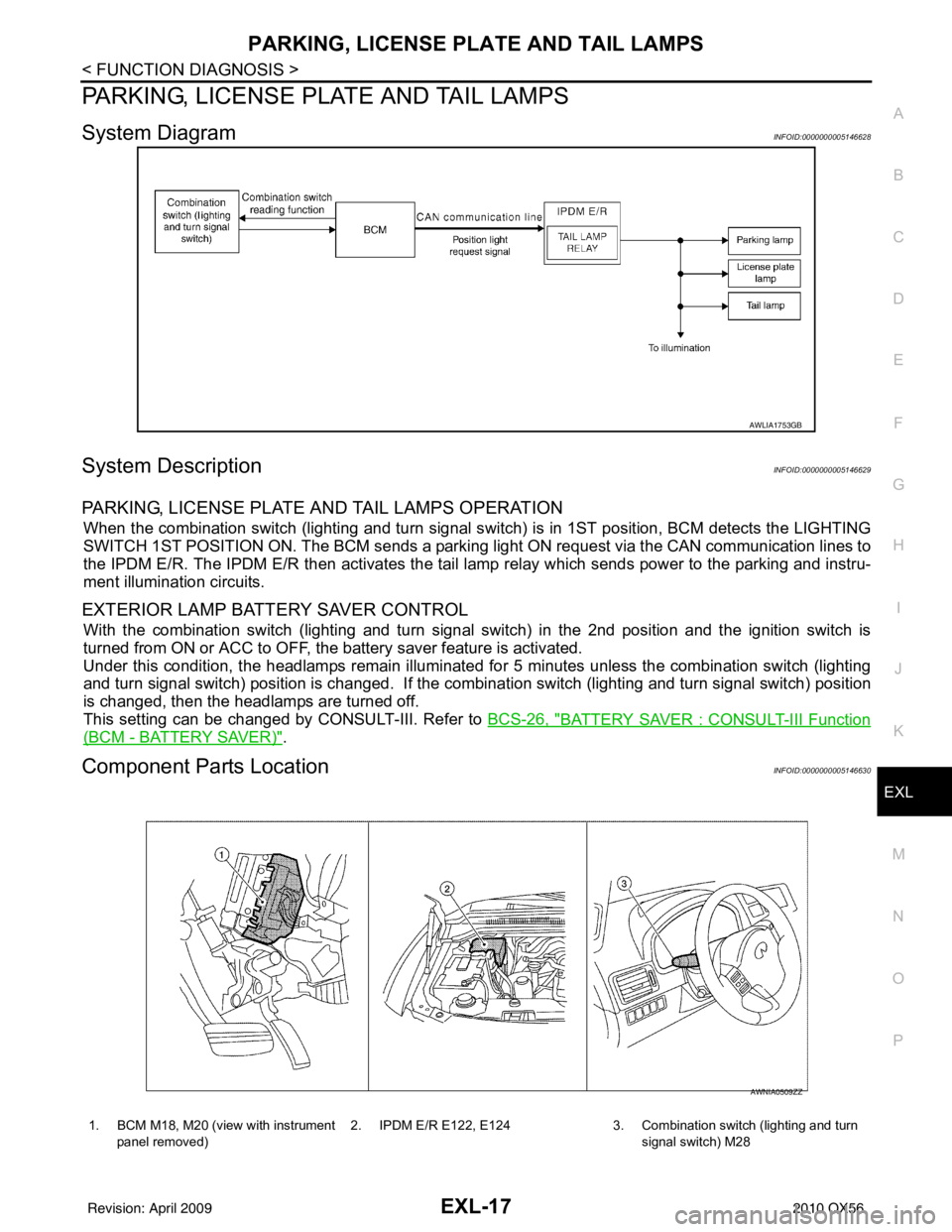
System DiagramINFOID:0000000005146628
System DescriptionINFOID:0000000005146629
PARKING, LICENSE PLATE AND TAIL LAMPS OPERATION
When the combination switch (lighting and turn signal s witch) is in 1ST position, BCM detects the LIGHTING
SWITCH 1ST POSITION ON. The BCM sends a parking light ON request via the CAN communication lines to
the IPDM E/R. The IPDM E/R then ac tivates the tail lamp relay which sends power to the parking and instru-
ment illumination circuits.
EXTERIOR LAMP BATTERY SAVER CONTROL
With the combination switch (lighting and turn signal switch) in the 2nd position and the ignition switch is
turned from ON or ACC to OFF, the battery saver feature is activated.
Under this condition, the headlamps remain illuminated fo r 5 minutes unless the combination switch (lighting
and turn signal switch) position is changed. If the combi nation switch (lighting and turn signal switch) position
is changed, then the headlamps are turned off.
This setting can be changed by CONSULT-III. Refer to BCS-26, "
BATTERY SAVER : CONSULT-III Function
(BCM - BATTERY SAVER)".
Component Parts LocationINFOID:0000000005146630
AWLIA1753GB
1. BCM M18, M20 (view with instrument
panel removed) 2. IPDM E/R E122, E124 3. Combination switch (lighting and turn
signal switch) M28
AWNIA0509ZZ
Revision: April 20092010 QX56