2010 INFINITI QX56 TM-50
[x] Cancel search: TM-50Page 957 of 4210
![INFINITI QX56 2010 Factory Service Manual AUTOMATIC BACK DOOR SELF-DIAGNOSIS PROCEDUREDLK-123
< COMPONENT DIAGNOSIS > [WITH INTELLIGENT KEY SYSTEM]
C
D
E
F
G H
I
J
L
M A
B
DLK
N
O P
AUTOMATIC BACK DOOR SELF-DIAGNOSIS PROCEDURE
Self-Diagnosis](/manual-img/42/57032/w960_57032-956.png "INFINITI QX56 2010 Factory Service Manual AUTOMATIC BACK DOOR SELF-DIAGNOSIS PROCEDUREDLK-123
< COMPONENT DIAGNOSIS > [WITH INTELLIGENT KEY SYSTEM]
C
D
E
F
G H
I
J
L
M A
B
DLK
N
O P
AUTOMATIC BACK DOOR SELF-DIAGNOSIS PROCEDURE
Self-Diagnosis")
AUTOMATIC BACK DOOR SELF-DIAGNOSIS PROCEDUREDLK-123
< COMPONENT DIAGNOSIS > [WITH INTELLIGENT KEY SYSTEM]
C
D
E
F
G H
I
J
L
M A
B
DLK
N
O P
AUTOMATIC BACK DOOR SELF-DIAGNOSIS PROCEDURE
Self-Diagnosis ProcedureINFOID:0000000005146997
INPUT SIGNAL CHECK MODE
Input signal check mode allows testing of swit ch input signal to the back door control unit.
To activate input signal check mode on the automatic sliding door, perform the following steps:
1. Turn ignition switch OFF.
2. Turn back door close switch to CANCEL (system cancelled).
3. Place A/T selector lever in P position.
4. Using the inside emergency release lever, open the back door.
5. Have an assistant press and hold the back door handle switch.
6. While the assistant continues to hold the back door handle switch, turn ignition switch ON (DO NOT start
engine).
7. After approximately 5 seconds, the back door warning chime will sound for 0.5 seconds.
8. Release the back door handle switch.
9. Within 8 seconds of the back door warning chime sounding, press and hold the power liftgate switch.
10. After approximately 5 seconds, the back door warning chime will sound for 1 second.
11. Release the power liftgate switch.
12. The input signal check mode is now initialized.
The input signal check mode can test the following inputs. The back door warning chime will sound for approx-
imately 0.5 second each time a switch signal input oc curs. Use this test when one of these inputs is not
responding during normal automatic back door operation.
*Back door warning chime should sound as soon as vehicle moves.
Turn ignition switch OFF to end input signal check mode.
OPERATING CHECK MODE
Operating check mode allows self-diagnos is of the automatic back door system.
To activate operating check mode on the automatic back door, perform the following steps:
1. Turn ignition switch OFF.
2. Turn back door close switch to CANCEL (system cancelled).
3. Place A/T selector lever in P position.
4. Using the inside emergency release lever, open the back door.
5. Have an assistant press and hold the back door handle switch.
6. While the assistant continues to hold the back door handle switch, turn ignition switch ON (DO NOT start engine).
7. After approximately 5 seconds, the back door warning chime will sound for 0.5 second.
8. Release the back door handle switch.
Switch signal OperationRefer to
Power liftgate switch OFF → ONDLK-129
Back door close switch (CLOSE) OFF → ON DLK-131
Back door close switch (CANCEL) OFF → ON DLK-133
Back door handle switch OFF → ON DLK-140
A/T shift selector (park position switch) P position → other than P position DLK-101
Vehicle speed* Vehicle speedTM-50
Remote keyless entry signal Keyfob switch OFF → ON DLK-103
Door lock/unlock signal LOCK → UNLOCK DLK-74
Pinch strip LH signal OFF → ON DLK-135
Pinch strip RH signal OFF → ON DLK-135
Revision: April 20092010 QX56
Page 1814 of 4210
![INFINITI QX56 2010 Factory Service Manual ECM
EC-461
< ECU DIAGNOSIS > [VK56DE]
C
D
E
F
G H
I
J
K L
M A
EC
NP
OEVAP GROSS LEAK
P04550455—2×EC-254
EVAP VERY SML LEAK P04560456
×*42 ×EC-261
FUEL LEV SEN SLOSH P04600460—2×EC-269
FUEL LEV](/manual-img/42/57032/w960_57032-1813.png "INFINITI QX56 2010 Factory Service Manual ECM
EC-461
< ECU DIAGNOSIS > [VK56DE]
C
D
E
F
G H
I
J
K L
M A
EC
NP
OEVAP GROSS LEAK
P04550455—2×EC-254
EVAP VERY SML LEAK P04560456
×*42 ×EC-261
FUEL LEV SEN SLOSH P04600460—2×EC-269
FUEL LEV")
ECM
EC-461
< ECU DIAGNOSIS > [VK56DE]
C
D
E
F
G H
I
J
K L
M A
EC
NP
OEVAP GROSS LEAK
P04550455—2×EC-254
EVAP VERY SML LEAK P04560456
×*42 ×EC-261
FUEL LEV SEN SLOSH P04600460—2×EC-269
FUEL LEVEL SENSOR P04610461—2×EC-271
FUEL LEVL SEN/CIRC P04620462—2×EC-273
FUEL LEVL SEN/CIRC P04630463—2×EC-273
VEH SPEED SEN/CIRC*6P0500 0500—2×EC-275
ISC SYSTEM P05060506—2×EC-277
ISC SYSTEM P05070507—2×EC-279
PW ST P SEN/CIRC P05500550—2—EC-281
ECM BACK UP/CIRC P06030603—2×EC-284
ECM P06050605—1 or 2 × or — EC-286
ECM P06070607—1×EC-288
SENSOR POWER/CIRC P06430643—1×EC-289
TRANSMISSION CONT P07000700—1×TM-44
T/M RANGE SENSOR A P07050705—2×TM-45
FLUID TEMP SENSOR A P07100710—2×TM-73
INPUT SPEED SENSOR A P07170717—2×TM-48
OUTPUT SPEED SENSOR*6P0720 0720—2×TM-50
1GR INCORRECT RATION P07310731—2×TM-55
2GR INCORRECT RATION P07320732—2×TM-57
3GR INCORRECT RATION P07330733—2×TM-59
4GR INCORRECT RATION P07340734—2×TM-61
5GR INCORRECT RATION P07350735—2×TM-63
TORQUE CONVERTER P07400740—2×TM-65
TORQUE CONVERTER P07440744—2×TM-67
PC SOLENOID A P07450745—2×TM-69
P-N POS SW/CIRCUIT P08500850—2×EC-292
INTK TIM S/CIRC-B1 P11401140—2×EC-295
INTK TIM S/CIRC-B2 P11451145—2×EC-295
CLOSED LOOP-B1 P11481148—1×EC-299
CLOSED LOOP-B2 P11681168—1×EC-299
TCS C/U FUNCTN P12111211—2—EC-300
TCS/CIRC P12121212—2—EC-301
ENG OVER TEMP P12171217—1×EC-36
CTP LEARNING-B1 P12251225—2—EC-306
CTP LEARNING-B1 P12261226—2—EC-308
COLD START CONTROL P14211421—2×EC-310
BAT CURRENT SENSOR P15501550—2—EC-312
BAT CURRENT SENSOR P15511551—2—EC-316
BAT CURRENT SENSOR P15521552—2—EC-316
BAT CURRENT SENSOR P15531553—2—EC-320
Items
(CONSULT-IIl screen terms) DTC*
1
SRT code Trip
MILReference
page
CONSULT-IIl
GST*
2ECM*3
Revision: April 20092010 QX56
Page 3734 of 4210
DIAGNOSIS SYSTEM (TCM)TM-39
< FUNCTION DIAGNOSIS >
CEF
G H
I
J
K L
M A
B
TM
N
O P
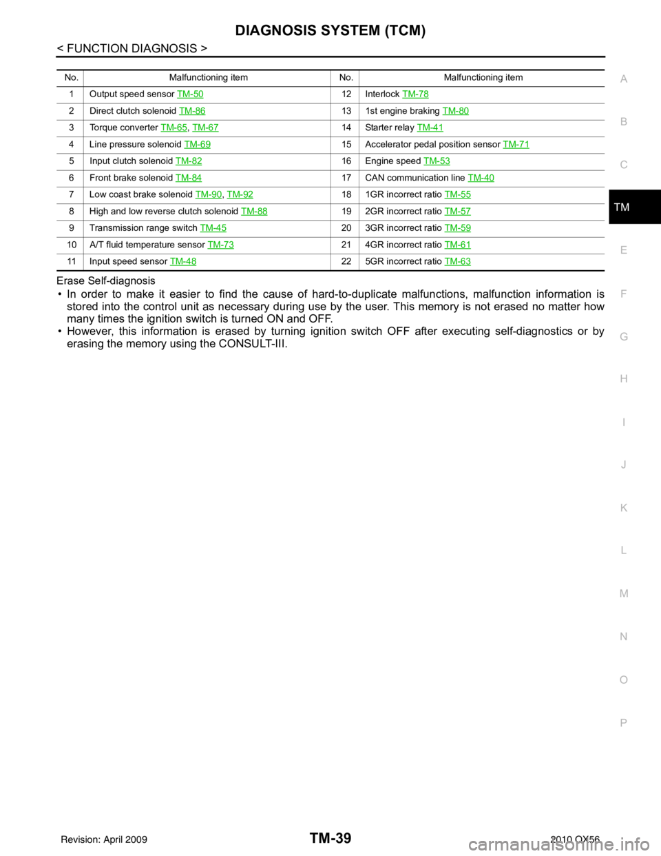
Erase Self-diagnosis
• In order to make it easier to find the cause of
hard-to-duplicate malfunctions, malfunction information is
stored into the control unit as necessary during use by the user. This memory is not erased no matter how
many times the ignition switch is turned ON and OFF.
• However, this information is erased by turning ignition switch OFF after executing self-diagnostics or by erasing the memory using the CONSULT-III.
No. Malfunctioning item No.Malfunctioning item
1 Output speed sensor TM-50
12 Interlock TM-78
2 Direct clutch solenoid TM-8613 1st engine braking TM-80
3 Torque converter TM-65, TM-6714 Starter relay TM-41
4 Line pressure solenoid TM-6915 Accelerator pedal position sensor TM-71
5 Input clutch solenoid TM-8216 Engine speed TM-53
6 Front brake solenoid TM-8417 CAN communication line TM-40
7 Low coast brake solenoid TM-90, TM-9218 1GR incorrect ratio TM-55
8 High and low reverse clutch solenoid TM-8819 2GR incorrect ratio TM-57
9 Transmission range switch TM-4520 3GR incorrect ratio TM-59
10 A/T fluid temperature sensor TM-7321 4GR incorrect ratio TM-61
11 Input speed sensor TM-4822 5GR incorrect ratio TM-63
Revision: April 20092010 QX56
Page 3745 of 4210
TM-50
< COMPONENT DIAGNOSIS >
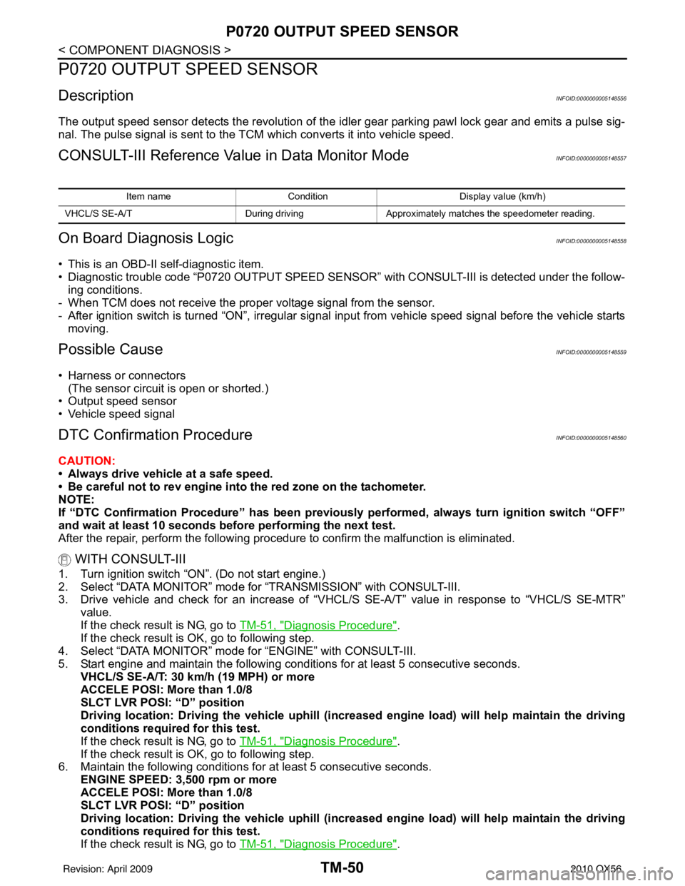
P0720 OUTPUT SPEED SENSOR
P0720 OUTPUT SPEED SENSOR
DescriptionINFOID:0000000005148556
The output speed sensor detects the revolution of the idler gear parking pawl lock gear and emits a pulse sig-
nal. The pulse signal is sent to the TCM which converts it into vehicle speed.
CONSULT-III Reference Value in Data Monitor ModeINFOID:0000000005148557
On Board Diagn osis LogicINFOID:0000000005148558
• This is an OBD-II self-diagnostic item.
• Diagnostic trouble code “P0720 OUTPUT SPEED SENSOR” with CONSULT-III is detected under the follow-
ing conditions.
- When TCM does not receive the proper voltage signal from the sensor.
- After ignition switch is turned “ON”, irregular signal input from vehicle speed signal before the vehicle starts
moving.
Possible CauseINFOID:0000000005148559
• Harness or connectors (The sensor circuit is open or shorted.)
• Output speed sensor
• Vehicle speed signal
DTC Confirmation ProcedureINFOID:0000000005148560
CAUTION:
• Always drive vehicle at a safe speed.
• Be careful not to rev engine into the red zone on the tachometer.
NOTE:
If “DTC Confirmation Procedure” has been previously performed, always turn ignition switch “OFF”
and wait at least 10 seconds before performing the next test.
After the repair, perform the following proc edure to confirm the malfunction is eliminated.
WITH CONSULT-III
1. Turn ignition switch “ON”. (Do not start engine.)
2. Select “DATA MONITOR” mode for “TRANSMISSION” with CONSULT-III.
3. Drive vehicle and check for an increase of “VHCL/ S SE-A/T” value in response to “VHCL/S SE-MTR”
value.
If the check result is NG, go to TM-51, "
Diagnosis Procedure".
If the check result is OK, go to following step.
4. Select “DATA MONITOR” mode for “ENGINE” with CONSULT-III.
5. Start engine and maintain the following conditions for at least 5 consecutive seconds. VHCL/S SE-A/T: 30 km/h (19 MPH) or more
ACCELE POSI: More than 1.0/8
SLCT LVR POSI: “D” position
Driving location: Driving the vehicle uphill (increased engine load) will help maintain the driving
conditions required for this test.
If the check result is NG, go to TM-51, "
Diagnosis Procedure".
If the check result is OK, go to following step.
6. Maintain the following conditions for at least 5 consecutive seconds. ENGINE SPEED: 3,500 rpm or more
ACCELE POSI: More than 1.0/8
SLCT LVR POSI: “D” position
Driving location: Driving the vehicle uphill (increased engine load) will help maintain the driving
conditions required for this test.
If the check result is NG, go to TM-51, "
Diagnosis Procedure".
Item name Condition Display value (km/h)
VHCL/S SE-A/T During driving Approximately matches the speedometer reading.
Revision: April 20092010 QX56
Page 3747 of 4210

TM-52
< COMPONENT DIAGNOSIS >
P0720 OUTPUT SPEED SENSOR
5.REPLACE THE OUTPUT SPEED SENSOR AND CHECK DTC
1. Replace the output speed sensor. Refer to TM-204, "
Disassembly".
2. Perform “DTC Confirmation Procedure”. Refer to TM-50, "
DTC Confirmation Procedure".
OK or NG
OK >> INSPECTION END
NG >> Replace the control valve with TCM. Refer to TM-172, "
Control Valve with TCM and A/T Fluid
Temperature Sensor 2 and Plug".
6.CHECK DTC
Perform “DTC Confirmation Procedure”.
• Refer to TM-50, "
DTC Confirmation Procedure".
OK or NG
OK >> INSPECTION END
NG >> GO TO 2.
Revision: April 20092010 QX56
Page 3816 of 4210
SYSTEM SYMPTOMTM-121
< SYMPTOM DIAGNOSIS >
CEF
G H
I
J
K L
M A
B
TM
N
O P
SYMPTOM DIAGNOSIS
SYSTEM SYMPTOM
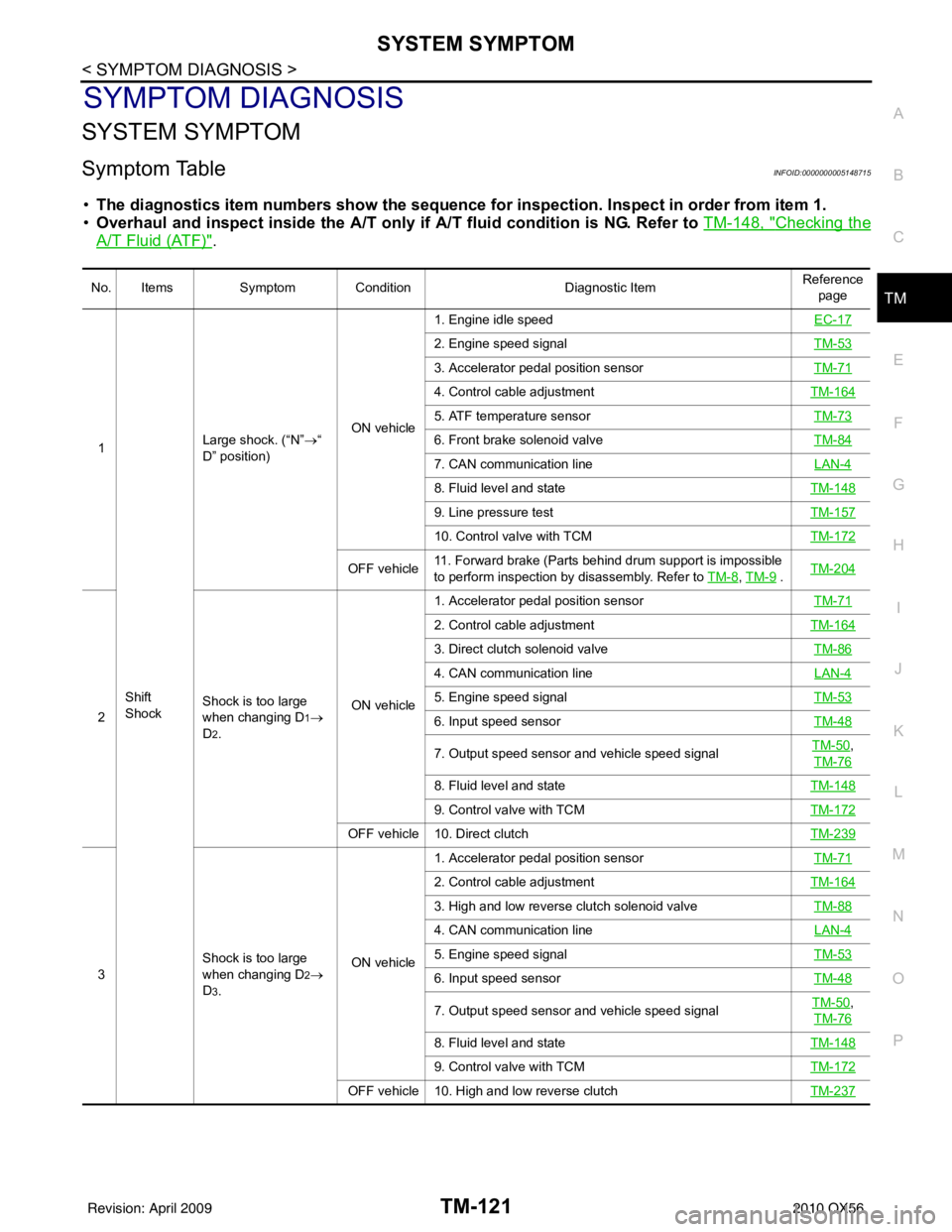
Symptom TableINFOID:0000000005148715
• The diagnostics item numbers s how the sequence for inspection. Inspect in order from item 1.
• Overhaul and inspect inside the A/T only if A/T fluid condition is NG. Refer to TM-148, "
Checking the
A/T Fluid (ATF)".
No. ItemsSymptom Condition Diagnostic ItemReference
page
1
Shift
Shock Large shock. (“N”
→“
D” position) ON vehicle1. Engine idle speed
EC-17
2. Engine speed signalTM-53
3. Accelerator pedal position sensorTM-71
4. Control cable adjustmentTM-164
5. ATF temperature sensor TM-73
6. Front brake solenoid valveTM-84
7. CAN communication line LAN-4
8. Fluid level and stateTM-148
9. Line pressure testTM-157
10. Control valve with TCMTM-172
OFF vehicle11. Forward brake (Parts behind drum support is impossible
to perform inspection by disassembly. Refer to
TM-8, TM-9 . TM-204
2 Shock is too large
when changing D1→
D
2. ON vehicle1. Accelerator pedal position sensor
TM-71
2. Control cable adjustmentTM-164
3. Direct clutch solenoid valve TM-86
4. CAN communication line LAN-4
5. Engine speed signalTM-53
6. Input speed sensorTM-48
7. Output speed sensor and vehicle speed signalTM-50,
TM-76
8. Fluid level and state TM-148
9. Control valve with TCMTM-172
OFF vehicle 10. Direct clutch TM-239
3Shock is too large
when changing D2→
D
3. ON vehicle1. Accelerator pedal position sensor
TM-71
2. Control cable adjustmentTM-164
3. High and low reverse clutch solenoid valve TM-88
4. CAN communication line LAN-4
5. Engine speed signalTM-53
6. Input speed sensorTM-48
7. Output speed sensor and vehicle speed signalTM-50,
TM-76
8. Fluid level and state TM-148
9. Control valve with TCMTM-172
OFF vehicle 10. High and low reverse clutch TM-237
Revision: April 20092010 QX56
Page 3817 of 4210

TM-122
< SYMPTOM DIAGNOSIS >
SYSTEM SYMPTOM
4Shift
Shock Shock is too large
when changing D3→
D
4. ON vehicle1. Accelerator pedal position sensor
TM-71
2. Control cable adjustmentTM-164
3. Input clutch solenoid valve TM-82
4. CAN communication line LAN-4
5. Engine speed signalTM-53
6. Input speed sensorTM-48
7. Output speed sensor and vehicle speed signalTM-50,
TM-76
8. Fluid level and state TM-148
9. Control valve with TCMTM-172
OFF vehicle 10. Input clutch TM-227
5Shock is too large
when changing D4→
D
5. ON vehicle1. Accelerator pedal position sensor
TM-71
2. Control cable adjustmentTM-164
3. Front brake solenoid valve TM-84
4. CAN communication line LAN-4
5. Engine speed signalTM-53
6. Input speed sensorTM-48
7. Output speed sensor and vehicle speed signalTM-50,
TM-76
8. Fluid level and state TM-148
9. Control valve with TCMTM-172
OFF vehicle10. Front brake (brake band)
TM-19211. Input clutchTM-227
6Shock is too large for
downshift when accel-
erator pedal is
pressed. ON vehicle1. Accelerator pedal position sensor
TM-71
2. Control cable adjustmentTM-164
3. CAN communication line LAN-4
4. Engine speed signalTM-53
5. Input speed sensorTM-48
6. Output speed sensor and vehicle speed signalTM-50,
TM-76
7. Fluid level and state TM-148
8. Control valve with TCMTM-172
OFF vehicle9. Front brake (brake band)
TM-19210. Input clutchTM-227
11. High and low reverse clutchTM-237
12. Direct clutchTM-239
No. ItemsSymptom Condition Diagnostic ItemReference
page
Revision: April 20092010 QX56
Page 3818 of 4210
SYSTEM SYMPTOMTM-123
< SYMPTOM DIAGNOSIS >
CEF
G H
I
J
K L
M A
B
TM
N
O P
7
Shift
Shock Shock is too large for
upshift when accelera-
tor pedal is released.
ON vehicle1. Accelerator pedal position sensor
TM-71
2. Control cable adjustmentTM-164
3. Engine speed signal TM-53
4. CAN communication line LAN-4
5. Input speed sensorInput speed sensorTM-48
6. Output speed sensor and vehicle speed signalTM-50,
TM-76
7. Fluid level and state TM-148
8. Control valve with TCMTM-172
OFF vehicle9. Front brake (brake band)
TM-19210. Input clutchTM-227
11. High and low reverse clutchTM-237
12. Direct clutchTM-239
8Shock is too large for
lock-up. ON vehicle1. Accelerator pedal position sensor
TM-71
2. Control cable adjustmentTM-164
3. Engine speed signal TM-53
4. CAN communication line LAN-4
5. Input speed sensorTM-48
6. Output speed sensor and vehicle speed signalTM-50,
TM-76
7. Torque converter clutch solenoid valve TM-65
8. Fluid level and stateTM-148
9. Control valve with TCMTM-172
OFF vehicle 10. Torque converter TM-172
9Shock is too large dur-
ing engine brake. ON vehicle
1. Accelerator pedal position sensor
TM-71
2. Control cable adjustmentTM-164
3. CAN communication line LAN-4
4. Fluid level and stateTM-148
5. Control valve with TCMTM-172
OFF vehicle6. Front brake (brake band)
TM-1727. Input clutchTM-172
8. High and low reverse clutchTM-172
9. Direct clutchTM-172
No. ItemsSymptom Condition Diagnostic ItemReference
page
Revision: April 20092010 QX56