Page 3873 of 4210
TM-178
< ON-VEHICLE REPAIR >
CONTROL VALVE WITH TCM
i. Install new O-ring (1) in plug (2).CAUTION:
• Do not reuse O-ring.
• Apply ATF to O-ring.
• O-ring should be free of contamination.
ii. Install plug (2) to bracket (1).
iii. Install plug (1) [with bracket (2)] to control valve with TCM. Tighten plug bolt ( ) to the specified torque.
CAUTION:
Adjust bolt hole of bracket to bolt hole of control valve with
TCM.
6. Install control valve with TCM in transmission case. CAUTION:
• Make sure that input speed sensor is securely installedinto input speed sensor hole (A).
• Hang down output speed sen sor harness toward outside
so as not to disturb installati on of control valve with TCM.
• Adjust A/T assembly harness co nnector of control valve
with TCM to terminal hole of transmission case.
• Assemble it so that manual valve cutout is engaged with manual plate projection.
JSDIA1313ZZ
JSDIA1312ZZ
JSDIA1311ZZ
1 : Brake band
JSDIA1318ZZ
SCIA5142E
Revision: April 20092010 QX56
Page 3956 of 4210
![INFINITI QX56 2010 Factory Service Manual ASSEMBLYTM-261
< DISASSEMBLY AND ASSEMBLY >
CEF
G H
I
J
K L
M A
B
TM
N
O P
iii. Install plug (1) [with bracket (2)] to control valve with TCM and tighten bolt ( ) to specified torque.
CAUTION:
Adjust INFINITI QX56 2010 Factory Service Manual ASSEMBLYTM-261
< DISASSEMBLY AND ASSEMBLY >
CEF
G H
I
J
K L
M A
B
TM
N
O P
iii. Install plug (1) [with bracket (2)] to control valve with TCM and tighten bolt ( ) to specified torque.
CAUTION:
Adjust](/manual-img/42/57032/w960_57032-3955.png)
ASSEMBLYTM-261
< DISASSEMBLY AND ASSEMBLY >
CEF
G H
I
J
K L
M A
B
TM
N
O P
iii. Install plug (1) [with bracket (2)] to control valve with TCM and tighten bolt ( ) to specified torque.
CAUTION:
Adjust bolt hole of bracket to bolt hole of control valve.
14. Install control valve with TCM in transmission case. CAUTION:
• Make sure that input speed sensor is securely installed
into input speed sensor hole (A).
• Hang down output speed sensor harness toward outside so as not to disturb installati on of control valve with TCM.
• Adjust A/T assembly harness connector of control valve
with TCM to terminal hole of transmission case.
• Assemble it so that manual valve cutout is engaged with
manual plate projection.
15. Install bolts (A), (B) and (C) to control valve with TCM.
16. Tighten bolt (A), (B) and (C) temporarily to prevent dislocation. After that tighten them in order (A → B → C), and then tighten
other bolts. Bracket bolt : 7.9 N·m (0.81 kg-m, 70 in-lb)
JSDIA1311ZZ
1 : Brake band
JSDIA1318ZZ
SCIA5035E
: Front
Bolt symbol Length mm (in) Number of bolts
A 42 (1.65) 5
B 55 (2.17) 6
C 40 (1.57) 1
SCIA8077E
: Front
Bolt symbol A B C
Number of bolts 5 6 1
Length mm (in) 42 (1.65) 55 (2.17) 40 (1.57)
SCIA8078E
Revision: April 20092010 QX56
Page 3960 of 4210

SERVICE DATA AND SPECIFICATIONS (SDS)TM-265
< SERVICE DATA AND SPECIFICATIONS (SDS)
CEF
G H
I
J
K L
M A
B
TM
N
O P
SERVICE DATA AND SPECIFICATIONS (SDS)
SERVICE DATA AND SPECIFICATIONS (SDS)
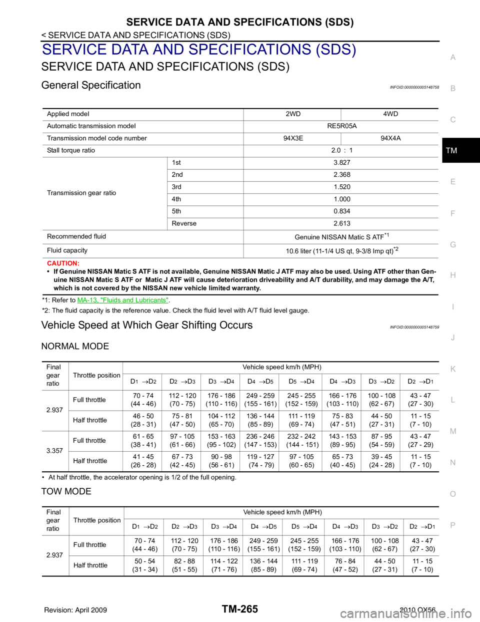
General SpecificationINFOID:0000000005148758
*1: Refer to MA-13, "Fluids and Lubricants".
*2: The fluid capacity is the reference value. Check the fluid level with A/T fluid level gauge.
Vehicle Speed at Which Gear Shifting OccursINFOID:0000000005148759
NORMAL MODE
• At half throttle, the accelerator opening is 1/2 of the full opening.
TOW MODE
Applied model 2WD4WD
Automatic transmission model RE5R05A
Transmission model code number 94X3E94X4A
Stall torque ratio 2.0 : 1
Transmission gear ratio 1st
3.827
2nd 2.368
3rd 1.520
4th 1.000
5th 0.834
Reverse 2.613
Recommended fluid Genuine NISSAN Matic S ATF
*1
Fluid capacity10.6 liter (11-1/4 US qt, 9-3/8 Imp qt)*2
CAUTION:
• If Genuine NISSAN Matic S ATF is not available, Genuine NISSAN Matic J ATF may also be used. Using ATF other than Gen-
uine NISSAN Matic S ATF or Matic J ATF will cause deterioration driveability and A/T durability, and may damage the A/T,
which is not covered by the NISSAN new vehicle limited warranty.
Final
gear
ratio Throttle position
Vehicle speed km/h (MPH)
D
1 → D2D2 →D3D3 →D4D4 →D5D5 →D4D4 →D3D3 → D2D2 →D1
2.937 Full throttle
70 - 74
(44 - 46) 112 - 120
(70 - 75) 176 - 186
(110 - 116) 249 - 259
(155 - 161) 245 - 255
(152 - 159) 166 - 176
(103 - 110) 100 - 108
(62 - 67) 43 - 47
(27 - 30)
Half throttle 46 - 50
(28 - 31) 75 - 81
(47 - 50) 104 - 112
(65 - 70) 136 - 144
(85 - 89) 111 - 11 9
(69 - 74) 75 - 83
(47 - 51) 44 - 50
(27 - 31) 11 - 1 5
(7 - 10)
3.357 Full throttle
61 - 65
(38 - 41) 97 - 105
(61 - 66) 153 - 163
(95 - 102) 236 - 246
(147 - 153) 232 - 242
(144 - 151) 143 - 153
(89 - 95) 87 - 95
(54 - 59) 43 - 47
(27 - 29)
Half throttle 41 - 45
(26 - 28) 67 - 73
(42 - 45) 90 - 98
(56 - 61) 11 9 - 1 2 7
(74 - 79) 97 - 105
(60 - 65) 65 - 73
(40 - 45) 39 - 45
(24 - 28) 11 - 1 5
(7 - 10)
Final
gear
ratio Throttle position Vehicle speed km/h (MPH)
D
1 → D2D2 →D3D3 →D4D4 →D5D5 →D4D4 →D3D3 → D2D2 →D1
2.937 Full throttle
70 - 74
(44 - 46) 112 - 120
(70 - 75) 176 - 186
(110 - 116) 249 - 259
(155 - 161) 245 - 255
(152 - 159) 166 - 176
(103 - 110) 100 - 108
(62 - 67) 43 - 47
(27 - 30)
Half throttle 50 - 54
(31 - 34) 82 - 88
(51 - 55) 114 - 122
(71 - 76) 136 - 144
(85 - 89) 111 - 11 9
(69 - 74) 76 - 84
(47 - 52) 44 - 50
(27 - 31) 11 - 1 5
(7 - 10)
Revision: April 20092010 QX56
Page 4183 of 4210

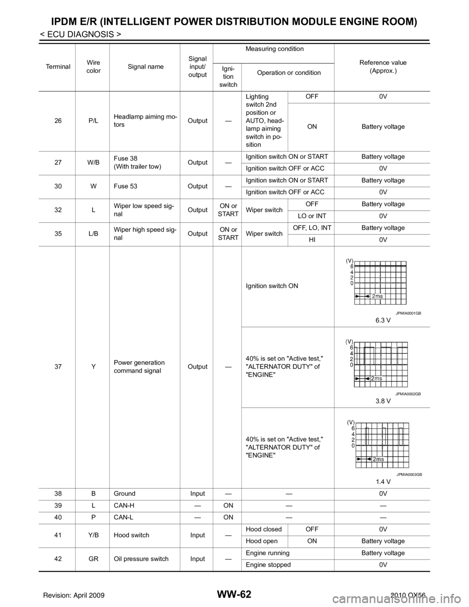
WW-62
< ECU DIAGNOSIS >
IPDM E/R (INTELLIGENT POWER DISTRIBUTION MODULE ENGINE ROOM)
26 P/LHeadlamp aiming mo-
tors
Output —Lighting
switch 2nd
position or
AUTO, head-
lamp aiming
switch in po-
sition OFF
0V
ON Battery voltage
27 W/B Fuse 38
(With trailer tow)
Output —Ignition switch ON or START
Battery voltage
Ignition switch OFF or ACC 0V
30 W Fuse 53 Output —Ignition switch ON or START
Battery voltage
Ignition switch OFF or ACC 0V
32 L Wiper low speed sig-
nal
OutputON or
START Wiper switch OFF
Battery voltage
LO or INT 0V
35 L/B Wiper high speed sig-
nal
OutputON or
START Wiper switch OFF, LO, INT Battery voltage
HI 0V
37 Y Power generation
command signal Output —Ignition switch ON
6.3 V
40% is set on "Active test,"
"ALTERNATOR DUTY" of
"ENGINE" 3.8 V
40% is set on "Active test,"
"ALTERNATOR DUTY" of
"ENGINE" 1.4 V
38 B Ground Input ——0V
39 L CAN-H — ON— —
40 P CAN-L — ON— —
41 Y/B Hood switch Input —Hood closed OFF
0V
Hood open ON Battery voltage
42 GR Oil pressure switch Input — Engine running
Battery voltage
Engine stopped 0V
Te r m i n a l
Wire
color Signal name Signal
input/
output Measuring condition
Reference value(Approx.)
Igni-
tion
switch Operation or condition
JPMIA0001GB
JPMIA0002GB
JPMIA0003GB
Revision: April 20092010 QX56
Page 4184 of 4210

IPDM E/R (INTELLIGENT POWER DISTRIBUTION MODULE ENGINE ROOM)
WW-63
< ECU DIAGNOSIS >
C
D E
F
G H
I
J
K
M A
B
WW
N
O P
43 L/Y Wiper auto stop signal Input ON or
START Wiper switch OFF, LO, INT Battery voltage
44 BR Daytime light relay
control
(Canada only) Input ONDaytime light system active
0V
Daytime light system inactive Battery voltage
45 G/W Horn relay control Input ON When door locks are operated
using Intelligent Key (OFF
→
ON)* Battery voltage
→ 0V
46 GR Fuel pump relay con-
trol Input —Ignition switch ON or START
0V
Ignition switch OFF or ACC Battery voltage
47 O Throttle control motor
relay control Input —Ignition switch ON or START
0V
Ignition switch OFF or ACC Battery voltage
48 B/R Starter relay (inhibit
switch) Input
ON or
START Selector lever in "P" or "N"
0V
Selector lever any other posi-
tion Battery voltage
49 R/L Trailer tow relay
(With trailer tow)
Illumination
(Without trailer tow) Output ONLighting
switch must
be in the 1st
position OFF
0V
ON Battery voltage
50 W/R Front fog lamp (LH) Output ON or
START Lighting
switch must
be in the 2nd
position
(LOW beam
is ON) and
the front fog
lamp switch OFF
0V
ON Battery voltage
51 W/R Front fog lamp (RH) Output ON or
START Lighting
switch must
be in the 2nd
position
(LOW beam
is ON) and
the front fog
lamp switch OFF
0V
ON Battery voltage
52 L LH low beam head-
lamp
Output — Lighting switch in 2nd position Battery voltage
54 R/Y RH low beam head-
lamp Output — Lighting switch in 2nd position Battery voltage
55 G LH high beam head-
lamp Output —Lighting switch in 2nd position
and placed in HIGH or PASS
position Battery voltage
56 Y
(With
DTRL)
L/W
(Without DTRL) RH high beam head-
lamp
Output —Lighting switch in 2nd position
and placed in HIGH or PASS
position
Battery voltage
57 R/LPa
rking, license, and
tail lamp Output ONLighting
switch 1st po-
sition OFF
0V
ON Battery voltage
59 B Ground Input ——0V
Te r m i n a l
Wire
color Signal name Signal
input/
output Measuring condition
Reference value(Approx.)
Igni-
tion
switch Operation or condition
Revision: April 20092010 QX56
Page 4185 of 4210
WW-64
< ECU DIAGNOSIS >
IPDM E/R (INTELLIGENT POWER DISTRIBUTION MODULE ENGINE ROOM)
*: When horn reminder is ON60 B/W
Rear window defog-
ger relay
OutputON or
START Rear defogger switch ON
Battery voltage
Rear defogger switch OFF 0V
61 BR Fuse 32
(With trailer tow) Output OFF
—Battery voltage
Te r m i n a l
Wire
color Signal name Signal
input/
output Measuring condition
Reference value(Approx.)
Igni-
tion
switch Operation or condition
Revision: April 20092010 QX56
Page 4209 of 4210
WW-88
< ON-VEHICLE REPAIR >
REAR WIPER AND WASHER SYSTEM
Rear Washer Tube Layout
INFOID:0000000005146811
NOTE:
Connect the check valve (2) to the washer fluid reservoir tube (1) so
that the directional arrow on the check valve (2) points towards the
washer nozzle tube (3).
Rear Washer NozzleINFOID:0000000005146812
REMOVAL AND INSTALLATION
Removal
1. Remove the rear spoiler. Refer to EXT-26, "Removal and Instal-
lation".
2. Release retaining clips, and remove washer nozzle.
Installation
Installation is in the reverse order of removal.
Rear Wiper and Washer SwitchINFOID:0000000005146813
REMOVAL AND INSTALLATION
Refer to WW-85, "Wiper and Washer Switch".
WKIA4566E
1. Rear washer nozzle 2. Washer fluid reservoir 3. Check valve
WKIA4242E
LKIA0418E
Revision: April 20092010 QX56