Page 3968 of 4210

VTL-6
< ON-VEHICLE MAINTENANCE >
IN-CABIN MICROFILTER
ON-VEHICLE MAINTENANCE
IN-CABIN MICROFILTER
Removal and InstallationINFOID:0000000005147604
REPLACEMENT PROCEDURE
1. Remove the glove box assembly from the instrument panel. Refer to IP-17, "Removal and Installation".
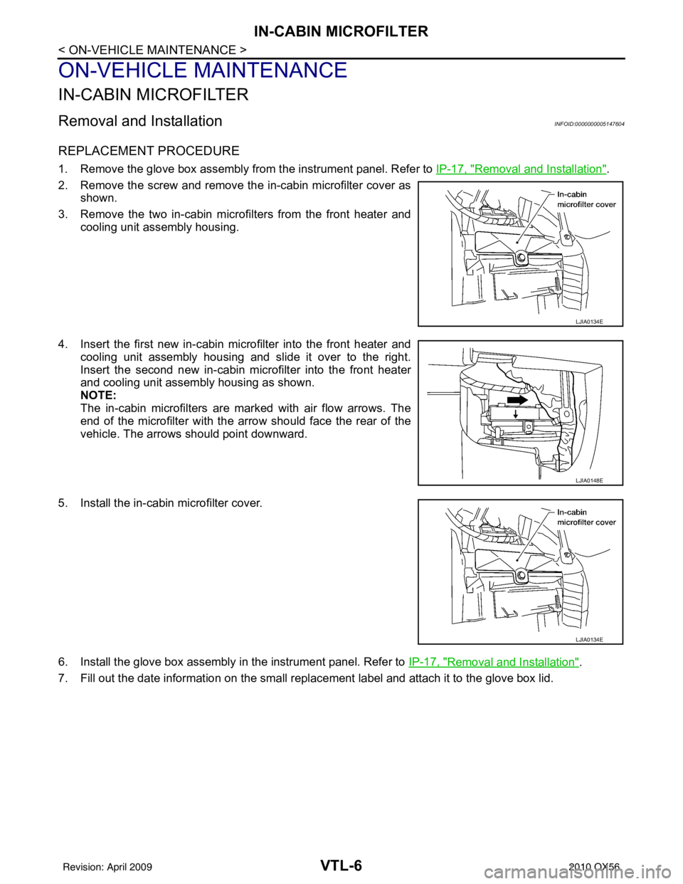
2. Remove the screw and remove the in-cabin microfilter cover as shown.
3. Remove the two in-cabin microf ilters from the front heater and
cooling unit assembly housing.
4. Insert the first new in-cabin micr ofilter into the front heater and
cooling unit assembly housing and slide it over to the right.
Insert the second new in-cabin mi crofilter into the front heater
and cooling unit assembly housing as shown.
NOTE:
The in-cabin microfilters are marked with air flow arrows. The
end of the microfilter with the arro w should face the rear of the
vehicle. The arrows should point downward.
5. Install the in-cabin microfilter cover.
6. Install the glove box assembly in the instrument panel. Refer to IP-17, "
Removal and Installation".
7. Fill out the date information on the small replac ement label and attach it to the glove box lid.
LJIA0134E
LJIA0148E
LJIA0134E
Revision: April 20092010 QX56
Page 3973 of 4210
INTAKE SENSORVTL-11
< ON-VEHICLE REPAIR >
C
DE
F
G H
J
K L
M A
B
VTL
N
O P
INTAKE SENSOR
Removal and InstallationINFOID:0000000005147608
REMOVAL
1. Remove the instrument lower panel RH and glove box. Refer to IP-17, "Removal and Installation".
2. Disconnect the intake sensor electrical connector. NOTE:
The intake sensor is located on the top of the front heater and
cooling unit assembly next to the A/C evaporator cover.
3. Pull up on the intake sensor to remove the intake sensor from the front heater and cooling unit assembly.
INSTALLATION
Installation is in the reverse order of removal.
LJIA0133E
Revision: April 20092010 QX56
Page 3974 of 4210
VTL-12
< ON-VEHICLE REPAIR >
BLOWER MOTOR
BLOWER MOTOR
ComponentINFOID:0000000005147609
Front Blower MotorRear Blower Motor
Removal and InstallationINFOID:0000000005147610
FRONT BLOWER MOTOR
Removal
1. Remove the glove box assembly. Refer to IP-17, "Removal and Installation".
2. Disconnect the front blower motor electrical connector.
3. Remove the three screws and remove the front blower motor.
4. Remove the blower motor wheel as necessary to transfer to the new blower motor.
Installation
Installation is in the reverse order of removal.
LJIA0136E
1. Front heater and cooling unit assembly 2. Front blower motor 3. Front variable blower control
AWIIA0085ZZ
1. Rear blower motor2. Rear heater and cooling unit assembly 3. Rear variable blower control
Revision: April 20092010 QX56
Page 3975 of 4210
BLOWER MOTORVTL-13
< ON-VEHICLE REPAIR >
C
DE
F
G H
J
K L
M A
B
VTL
N
O P
REAR BLOWER MOTOR
Removal
1. Remove the rear heater and cooling unit assembly. Refer to VTL-17, "Removal and Installation".
2. Disconnect the rear blower motor electrical connector.
3. Remove the three screws and remove the rear blower motor.
4. Remove the blower motor wheel as necessary to transfer to the new blower motor.
Installation
Installation is in the reverse order of removal.
Revision: April 20092010 QX56
Page 3976 of 4210
VTL-14
< ON-VEHICLE REPAIR >
VARIABLE BLOWER CONTROL
VARIABLE BLOWER CONTROL
ComponentsINFOID:0000000005147622
Front Variable Blower Control - Front Heater and Cooling Unit Assembly
LJIA0139E
1. Front heater and cooling unit assembly 2. Intake door motor3. Air mix door motor (driver)
4. Variable blower control 5. Air mix door motor (passenger) 6. Mode door motor
7. Defroster door motor
Revision: April 20092010 QX56
Page 3977 of 4210

VARIABLE BLOWER CONTROLVTL-15
< ON-VEHICLE REPAIR >
C
DE
F
G H
J
K L
M A
B
VTL
N
O P
Rear Variable Blower Control - Rear Heater and Cooling Unit Assembly
Removal and InstallationINFOID:0000000005147623
FRONT VARIABLE BLOWER CONTROL
Removal
1. Remove the glove box assembly. Refer to IP-17, "Removal and Installation".
2. Disconnect the variable blower control electrical connector.
3. Remove the two screws and remove the variable blower control.
Installation
Installation is in the reverse order of removal.
REAR VARIABLE BLOWER CONTROL
Removal
1. Remove the luggage side finisher lower RH. Refer to INT-19, "Removal and Installation".
2. Disconnect the rear blower motor resistor electrical connector.
3. Remove the two screws and remove the rear blower motor resistor.
Installation
Installation is in the reverse order of removal.
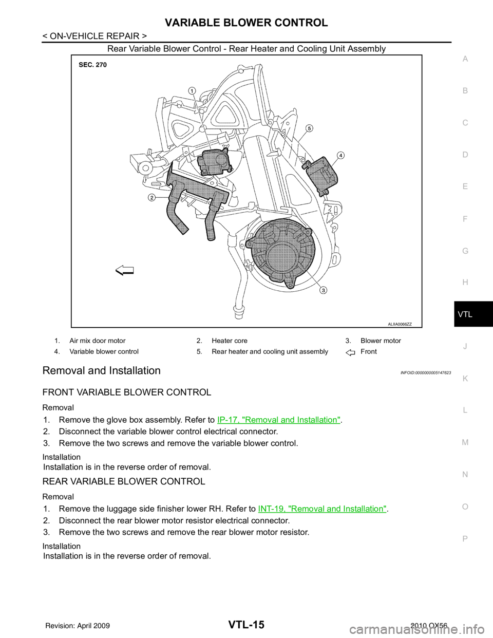
ALIIA0066ZZ
1. Air mix door motor 2. Heater core 3. Blower motor
4. Variable blower control 5. Rear heater and cooling unit assembly Front
Revision: April 20092010 QX56
Page 3978 of 4210
VTL-16
< ON-VEHICLE REPAIR >
HEATER & COOLING UNIT ASSEMBLY
HEATER & COOLING UNIT ASSEMBLY
ComponentINFOID:0000000005147612
Front A/C System
WJIA1578E
1. High-pressure service valve 2. Grommet3. High-pressure pipe
4. Refrigerant pressure sensor 5. Condenser 6. Compressor shaft seal
Revision: April 20092010 QX56
Page 3979 of 4210
HEATER & COOLING UNIT ASSEMBLYVTL-17
< ON-VEHICLE REPAIR >
C
DE
F
G H
J
K L
M A
B
VTL
N
O P
Rear A/C System
NOTE:
Refer to HA-5, "
Precaution for Refrigerant Connection".
Removal and InstallationINFOID:0000000005147613
FRONT HEATER AND COOLING UNIT ASSEMBLY
Removal
7. High-pressure flexible hose 8. Low-pressure flexible hose 9. Low-pressure service valve
10. Low-pressure pipe 11. Expansion valve (front) 12. Drain hose
AWIIA0134GB
1. Rear heater and cooling unit assembly 2. Rear A/C pipes 3. Rear A/C heater core pipes
4. Rear heater core hose 5. Rear blower motor6. Underfloor rear A/C pipes
7. Underfloor rear heater core pipes A. Bolt torque specification B. Leak checking order (l - r)
C. Tightening torque D. Wrench sizeE. O-ring size
Front
NOTE: The O-ring size 8 is the high-side and the O-ring size 16 is the low-side.
Revision: April 20092010 QX56