2010 INFINITI QX56 heater
[x] Cancel search: heaterPage 1825 of 4210
![INFINITI QX56 2010 Factory Service Manual EC-472
< ECU DIAGNOSIS >[VK56DE]
ECM
EGR
SYSTEM31H EGR function P0400 80H 96H
Low Flow Faults: EGR temp change
rate (short term)
P0400 81H 96H Low Flow Faults: EGR temp change
rate (long term)
P040 INFINITI QX56 2010 Factory Service Manual EC-472
< ECU DIAGNOSIS >[VK56DE]
ECM
EGR
SYSTEM31H EGR function P0400 80H 96H
Low Flow Faults: EGR temp change
rate (short term)
P0400 81H 96H Low Flow Faults: EGR temp change
rate (long term)
P040](/manual-img/42/57032/w960_57032-1824.png)
EC-472
< ECU DIAGNOSIS >[VK56DE]
ECM
EGR
SYSTEM31H EGR function P0400 80H 96H
Low Flow Faults: EGR temp change
rate (short term)
P0400 81H 96H Low Flow Faults: EGR temp change
rate (long term)
P0400 82H 96H Low Flow Faults: Difference between
max EGR temp and EGR temp under
idling condition
P0400 83H 96H Low Flow Faults: Max EGR temp
P1402 84H 96H High Flow Faults: EGR temp increase
rate
VVT
SYSTEM 35H VVT Monitor (Bank1)
P0011 80H 9DH
VTC intake function diagnosis (VTC
alignment check diagnosis)
P0014 81H 9DH VTC exhaust function diagnosis (VTC
alignment check diagnosis)
P0011 82H 9DH VTC intake function diagnosis (VTC
drive failure diagnosis)
P0014 83H 9DH VTC exhaust function diagnosis (VTC
drive failure diagnosis)
36H VVT Monitor (Bank2) P0021 80H 9DH
VTC intake function diagnosis (VTC
alignment check diagnosis)
P0024 81H 9DH VTC exhaust function diagnosis (VTC
alignment check diagnosis)
P0021 82H 9DH VTC intake function diagnosis (VTC
drive failure diagnosis)
P0024 83H 9DH VTC exhaust function diagnosis (VTC
drive failure diagnosis)
EVAP
SYSTEM 39H
EVAP control system leak
(Cap Off) P0455 80H 0CH
Difference in pressure sensor output
voltage before and after pull down
3BH EVAP control system leak
(Small leak) P0442 80H 05H
Leak area index (for more than 0.04
inch)
3CH EVAP control system leak
(Very small leak) P0456 80H 05H
Leak area index (for more than 0.02
inch)
P0456 81H FDH Maximum internal pressure of EVAP
system during monitoring
3DH Purge flow system P0441 83H 0CHDifference in pressure sensor output
voltage before and after vent control
valve close
O2 SEN-
SOR
HEATER 41H
A/F sensor 1 heater
(Bank 1) Low Input:P0031
High Input:P0032 81H 0BHConverted value of Heater electric cur-
rent to voltage
42H Heated oxygen sensor 2 heat-
er (Bank 1) Low Input:P0037
High Input:P0038 80H 0CH
Converted value of Heater electric cur-
rent to voltage
43H Heated oxygen sensor 3 heat-
er (Bank 1) P0043 80H 0CHConverted value of Heater electric cur-
rent to voltage
45H A/F sensor 1 heater
(Bank 2) Low Input:P0051
High Input:P0052 81
H
0BHConverted value of Heater electric cur-
rent to voltage
46H Heated oxygen sensor 2 heat-
er (Bank 2) Low Input:P0057
High Input:P0058 80H 0CH
Converted value of Heater electric cur-
rent to voltage
47H Heated oxygen sensor 3 heat-
er (Bank 2) P0063 80H 0CHConverted value of Heater electric cur-
rent to voltage
Item
OBD-
MID Self-diagnostic test item
DTCTest value and Test
limit
(GST display) Description
TID Unit and
Scaling ID
Revision: April 20092010 QX56
Page 1850 of 4210
![INFINITI QX56 2010 Factory Service Manual SERVICE DATA AND SPECIFICATIONS (SDS)EC-497
< SERVICE DATA AND SPECIFICATIONS (SDS) [VK56DE]
C
D
E
F
G H
I
J
K L
M A
EC
NP
O
SERVICE DATA AND SPECIFICATIONS (SDS)
SERVICE DATA AND SPECIFICATIONS (SDS INFINITI QX56 2010 Factory Service Manual SERVICE DATA AND SPECIFICATIONS (SDS)EC-497
< SERVICE DATA AND SPECIFICATIONS (SDS) [VK56DE]
C
D
E
F
G H
I
J
K L
M A
EC
NP
O
SERVICE DATA AND SPECIFICATIONS (SDS)
SERVICE DATA AND SPECIFICATIONS (SDS](/manual-img/42/57032/w960_57032-1849.png)
SERVICE DATA AND SPECIFICATIONS (SDS)EC-497
< SERVICE DATA AND SPECIFICATIONS (SDS) [VK56DE]
C
D
E
F
G H
I
J
K L
M A
EC
NP
O
SERVICE DATA AND SPECIFICATIONS (SDS)
SERVICE DATA AND SPECIFICATIONS (SDS)
Fuel PressureINFOID:0000000005149516
Idle Speed and Ignition TimingINFOID:0000000005149517
*: Under the following conditions:
• Air conditioner switch: OFF
• Electric load: OFF (Lights and heater fan)
• Steering wheel: Kept in straight-ahead position
Calculated Load ValueINFOID:0000000005149518
Mass Air Flow SensorINFOID:0000000005149519
*: Engine is warmed up to normal operating temperature and running under no load.
Intake Air Temperature SensorINFOID:0000000005149520
Engine Coolant Temperature SensorINFOID:0000000005149521
A/F Sensor 1 HeaterINFOID:0000000005149522
Fuel pressure at idling kPa (kg/cm2, psi)
Approximately 350 (3.57, 51)
Target idle speed
No-load* (in P or N position) 650±50 rpm
Air conditioner: ON In P or N position 700 rpm or more
Ignition timing In P or N position 15° ± 5 ° BTDC
Condition Calculated load value % (Using CONSULT-IIl or GST)
At idle 14.0 - 33.0
At 2,500 rpm 12.0 - 25.0
Supply voltageBattery voltage (11 - 14V)
Output voltage at idle 1.0 - 1.3V*
Mass air flow (Using CONSULT-IIl or GST) 3.0 - 9.0 g·m/sec at idle*
9.0 - 28.0 g·m/sec at 2,500 rpm*
Temperature °C ( °F) Resistance kΩ
25 (77) 1.800 - 2.200
Temperature °C ( °F) Resistance kΩ
20 (68) 2.1 - 2.9
50 (122) 0.68 - 1.00
90 (194) 0.236 - 0.260
Resistance [at 25°C (77 °F)] 1.98 - 2.66Ω
Revision: April 20092010 QX56
Page 1851 of 4210
![INFINITI QX56 2010 Factory Service Manual EC-498
< SERVICE DATA AND SPECIFICATIONS (SDS) [VK56DE]
SERVICE DATA AND SPECIFICATIONS (SDS)
Heated Oxygen sensor 2 Heater
INFOID:0000000005149523
Crankshaft Position Sensor (POS)INFOID:0000000005149 INFINITI QX56 2010 Factory Service Manual EC-498
< SERVICE DATA AND SPECIFICATIONS (SDS) [VK56DE]
SERVICE DATA AND SPECIFICATIONS (SDS)
Heated Oxygen sensor 2 Heater
INFOID:0000000005149523
Crankshaft Position Sensor (POS)INFOID:0000000005149](/manual-img/42/57032/w960_57032-1850.png)
EC-498
< SERVICE DATA AND SPECIFICATIONS (SDS) [VK56DE]
SERVICE DATA AND SPECIFICATIONS (SDS)
Heated Oxygen sensor 2 Heater
INFOID:0000000005149523
Crankshaft Position Sensor (POS)INFOID:0000000005149524
Refer to EC-203, "Component Inspection".
Camshaft Position Sensor (PHASE)INFOID:0000000005149525
Refer to EC-207, "Component Inspection".
Throttle Control MotorINFOID:0000000005149526
Fuel InjectorINFOID:0000000005149527
Fuel PumpINFOID:0000000005149528
Resistance [at 25 °C (77 °F)] 8 - 10 Ω
Resistance [at 25°C (77 °F)] Approximately 1 - 15 Ω
Resistance [at 10 - 60°C (50 - 140 °F)] 11.1 - 14.5Ω
Resistance [at 25 °C (77 °F)] 0.2 - 5.0 Ω
Revision: April 20092010 QX56
Page 1930 of 4210

ENGINE ASSEMBLYEM-79
< REMOVAL AND INSTALLATION >
C
DE
F
G H
I
J
K L
M A
EM
NP
O
1. Release the fuel pressure. Refer to
EC-489, "Fuel Pressure Check".
2. Drain the engine coolant. Refer to CO-11, "
Changing Engine Coolant".
3. Drain the engine oil. Refer to LU-9, "
Changing Engine Oil".
4. Partially drain the A/T fluid. Refer to TM-150, "
Changing the A/T Fluid (ATF)".
5. Disconnect the battery negative and positive terminal. Refer to PG-74, "
Removal and Installation".
6. Remove the engine hood. Refer to DLK-234, "
Removal and Installation of Hood Assembly".
7. Remove the cowl extension. Refer to EXT-18, "
Removal and Installation".
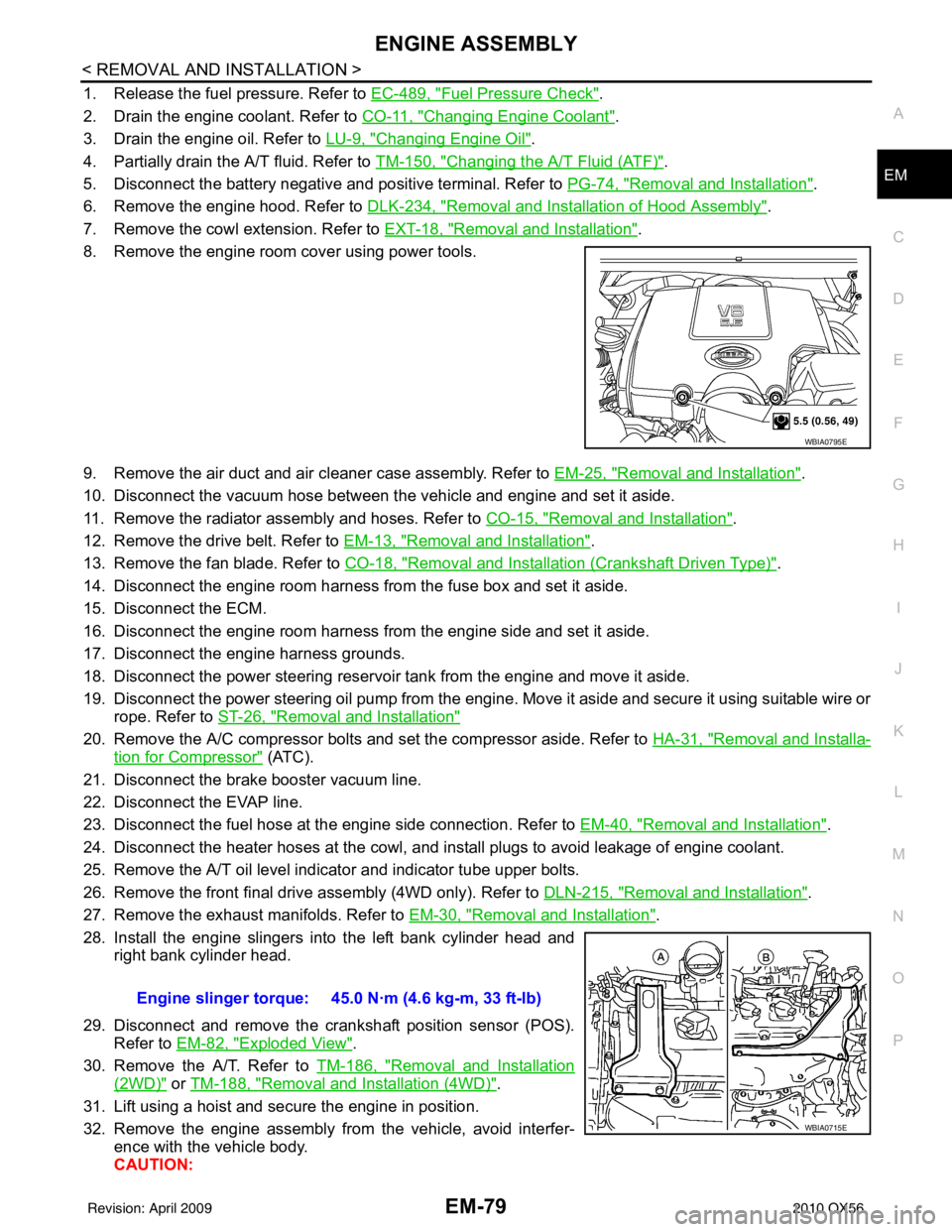
8. Remove the engine room cover using power tools.
9. Remove the air duct and air cleaner case assembly. Refer to EM-25, "
Removal and Installation".
10. Disconnect the vacuum hose between the vehicle and engine and set it aside.
11. Remove the radiator assembly and hoses. Refer to CO-15, "
Removal and Installation".
12. Remove the drive belt. Refer to EM-13, "
Removal and Installation".
13. Remove the fan blade. Refer to CO-18, "
Removal and Installation (Crankshaft Driven Type)".
14. Disconnect the engine room harness from the fuse box and set it aside.
15. Disconnect the ECM.
16. Disconnect the engine room harness from the engine side and set it aside.
17. Disconnect the engine harness grounds.
18. Disconnect the power steering reservoir t ank from the engine and move it aside.
19. Disconnect the power steering oil pump from the engine. Move it aside and secure it using suitable wire or rope. Refer to ST-26, "
Removal and Installation"
20. Remove the A/C compressor bolts and set the compressor aside. Refer to HA-31, "Removal and Installa-
tion for Compressor" (ATC).
21. Disconnect the brake booster vacuum line.
22. Disconnect the EVAP line.
23. Disconnect the fuel hose at the engine side connection. Refer to EM-40, "
Removal and Installation".
24. Disconnect the heater hoses at the cowl, and in stall plugs to avoid leakage of engine coolant.
25. Remove the A/T oil level indicator and indicator tube upper bolts.
26. Remove the front final drive assembly (4WD only). Refer to DLN-215, "
Removal and Installation".
27. Remove the exhaust manifolds. Refer to EM-30, "
Removal and Installation".
28. Install the engine slingers into the left bank cylinder head and right bank cylinder head.
29. Disconnect and remove the crankshaft position sensor (POS). Refer to EM-82, "
Exploded View".
30. Remove the A/T. Refer to TM-186, "
Removal and Installation
(2WD)" or TM-188, "Removal and Installation (4WD)".
31. Lift using a hoist and secure the engine in position.
32. Remove the engine assembly from the vehicle, avoid interfer- ence with the vehicle body.
CAUTION:
WBIA0795E
Engine slinger torque: 45.0 N·m (4.6 kg-m, 33 ft-lb)
WBIA0715E
Revision: April 20092010 QX56
Page 1934 of 4210

ENGINE UNITEM-83
< DISASSEMBLY AND ASSEMBLY >
C
DE
F
G H
I
J
K L
M A
EM
NP
O
Disassembly and AssemblyINFOID:0000000005149015
DISASSEMBLY
NOTE:
Explained here is how to disassemble with engine stand supporting transmission surface. When using differ-
ent type of engine stand, some steps may be different.
1. Remove engine assembly and mount to engine stand. Refer to
EM-78, "
Removal and Installation".
CAUTION:
Before removing the hanging chains, make sure engi ne stand is stable and there is no risk of over-
turning.
2. Drain engine oil. Refer to LU-9, "
Changing Engine Oil".
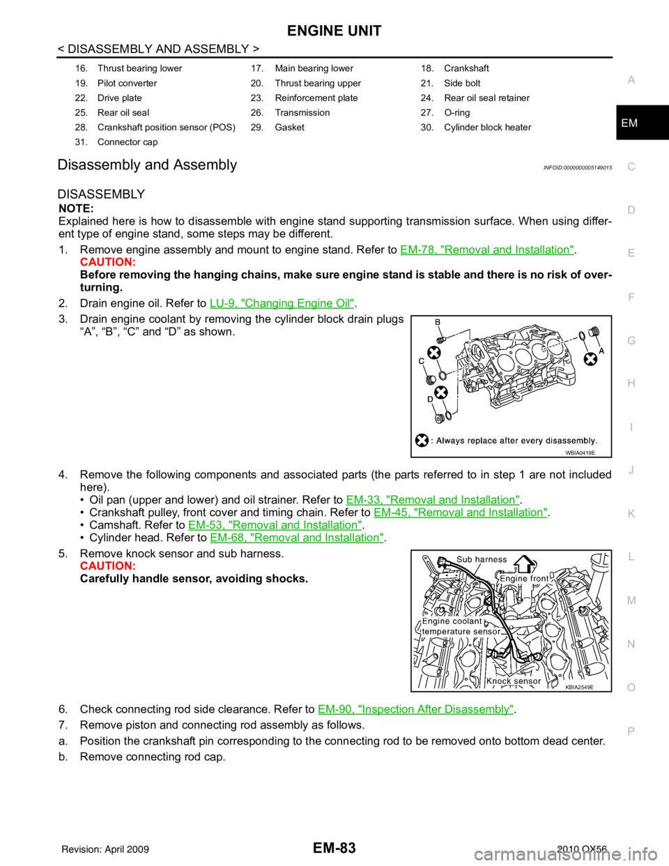
3. Drain engine coolant by removing the cylinder block drain plugs “A”, “B”, “C” and “D” as shown.
4. Remove the following components and associated parts (the parts referred to in step 1 are not included here).
• Oil pan (upper and lower) and oil strainer. Refer to EM-33, "
Removal and Installation".
• Crankshaft pulley, front cover and timing chain. Refer to EM-45, "
Removal and Installation".
• Camshaft. Refer to EM-53, "
Removal and Installation".
• Cylinder head. Refer to EM-68, "
Removal and Installation".
5. Remove knock sensor and sub harness. CAUTION:
Carefully handle sensor, avoiding shocks.
6. Check connecting rod side clearance. Refer to EM-90, "
Inspection After Disassembly".
7. Remove piston and connecting rod assembly as follows.
a. Position the crankshaft pin corresponding to the connecting rod to be removed onto bottom dead center.
b. Remove connecting rod cap.
16. Thrust bearing lower 17. Main bearing lower18. Crankshaft
19. Pilot converter 20. Thrust bearing upper21. Side bolt
22. Drive plate 23. Reinforcement plate24. Rear oil seal retainer
25. Rear oil seal 26. Transmission27. O-ring
28. Crankshaft position sensor (POS) 29. Gasket 30. Cylinder block heater
31. Connector cap
WBIA0419E
KBIA2549E
Revision: April 20092010 QX56
Page 2239 of 4210

GI-16
< HOW TO USE THIS MANUAL >
TERMINOLOGY
TERMINOLOGY
SAE J1930 Terminology ListINFOID:0000000005149582
All emission related terms used in this publication in accordance with SAE J1930 are listed. Accordingly, new
terms, new acronyms/abbreviations and old terms are listed in the following chart.
NEW TERMNEW ACRONYM /
ABBREVIATION OLD TERM
Air cleaner ACL Air cleaner
Barometric pressure BARO ***
Barometric pressure sensor-BCDD BAROS-BCDD BCDD
Camshaft position CMP ***
Camshaft position sensor CMPSCrank angle sensor
Canister *** Canister
Carburetor CARBCarburetor
Charge air cooler CACIntercooler
Closed loop CLClosed loop
Closed throttle position switch CTP switchIdle switch
Clutch pedal position switch CPP switch Clutch switch
Continuous fuel injection system CFI system***
Continuous trap oxidizer system CTOX system ***
Crankshaft position CKP***
Crankshaft position sensor CKPS***
Data link connector DLC***
Data link connector for CONSULT-III DLC for CONSULT-IIIDiagnostic connector for CONSULT-III
Diagnostic test mode DTMDiagnostic mode
Diagnostic test mode selector DTM selectorDiagnostic mode selector
Diagnostic test mode I DTM I Mode I
Diagnostic test mode II DTM IIMode II
Diagnostic trouble code DTCMalfunction code
Direct fuel injection system DFI system ***
Distributor ignition system DI system Ignition timing control
Early fuel evaporation-mixture heater EFE-mixture heater Mixture heater
Early fuel evaporation system EFE system Mixture heater control
Electrically erasable programmable read
only memory EEPROM
***
Electronic ignition system EI systemIgnition timing control
Engine control EC ***
Engine control module ECM ECCS control unit
Engine coolant temperature ECT Engine temperature
Engine coolant temperature sensor ECTS Engine temperature sensor
Engine modification EM ***
Engine speed RPM Engine speed
Erasable programmable read only memory EPROM ***
Evaporative emission canister EVAP canister Canister
Evaporative emission system EVAP system Canister control solenoid valve
Exhaust gas recirculation valve EGR valve EGR valve
Revision: April 20092010 QX56
Page 2293 of 4210

HA-1
VENTILATION, HEATER & AIR CONDITIONER
C
DE
F
G H
J
K L
M
SECTION HA
A
B
HA
N
O P
CONTENTS
HEATER & AIR CONDITIONING SYSTEM
PRECAUTION ....... ........................................3
PRECAUTIONS .............................................. .....3
Precaution for Supplemental Restraint System
(SRS) "AIR BAG" and "SEAT BELT PRE-TEN-
SIONER" ............................................................. ......
3
Precaution Necessary for Steering Wheel Rota-
tion After Battery Disconnect ............................... ......
3
Precaution for Working with HFC-134a (R-134a) ......4
Precaution for Procedure without Cowl Top Cover ......4
Contaminated Refrigerant .........................................4
General Refrigerant Precaution ................................5
Precaution for Leak Detection Dye ...........................5
A/C Identification Label .............................................5
Precaution for Refrigerant Connection ......................5
Precaution for Service of Compressor ................ ....10
Precaution for Service Equipment ....................... ....10
PREPARATION ...........................................13
PREPARATION .............................................. ....13
Special Service Tool ........................................... ....13
HFC-134a (R-134a) Service Tool and Equipment ....13
Commercial Service Tool ........................................16
FUNCTION DIAGNOSIS ..............................17
REFRIGERATION SYSTEM .......................... ....17
Refrigerant Cycle ................................................ ....17
Refrigerant System Protection ................................17
OIL .................................................................. ....19
Maintenance of Oil in Compressor ...................... ....19
ON-VEHICLE MAINTENANCE ....................20
REFRIGERATION SYSTEM .......................... ....20
HFC-134a (R-134a) Service Procedure ..................20
OIL .................................................................. ....22
Maintenance of Oil Quantity in Compressor ....... ....22
FLUORESCENT LEAK DETECTOR ................24
Checking of Refrigerant Leaks ................................24
Checking System for Leaks Using the Fluorescent
Dye Leak Detector ............................................... ....
24
Dye Injection ............................................................24
ELECTRICAL LEAK DETECTOR ....................26
Checking of Refrigerant Leaks ................................26
Electronic Refrigerant Leak Detector ................... ....26
ON-VEHICLE REPAIR .................................29
REFRIGERATION SYSTEM .............................29
Component .......................................................... ....29
COMPRESSOR .................................................31
Removal and Installation for Compressor ...............31
Removal and Installation for Compressor Clutch ....32
LOW-PRESSURE FLEXIBLE HOSE ................36
Removal and Installation for Low-Pressure Flexi-
ble Hose .............................................................. ....
36
LOW-PRESSURE PIPE ....................................37
Removal and Installation for Low-Pressure Pipe .....37
Removal and Installation for Rear High- and Low-
Pressure A/C and Heater Core Pipes ......................
37
Removal and Installation for Underfloor Rear
High- and Low-Pressure A/C and Heater Core
Pipes ........................................................................
38
HIGH-PRESSURE FLEXIBLE HOSE ...............40
Removal and Installation for High-Pressure Flexi-
ble Hose ..................................................................
40
HIGH-PRESSURE PIPE ....................................41
Removal and Installation for High-Pressure Pipe ....41
Removal and Installation for Rear High- and Low-
Pressure A/C and Heater Core Pipes .................. ....
41
Removal and Installation for Underfloor Rear
High- and Low-Pressure A/C and Heater Core
Pipes ........................................................................
42
Revision: April 20092010 QX56
Page 2300 of 4210

HA-8
< PRECAUTION >
PRECAUTIONS
Rear A/C
CAUTION:
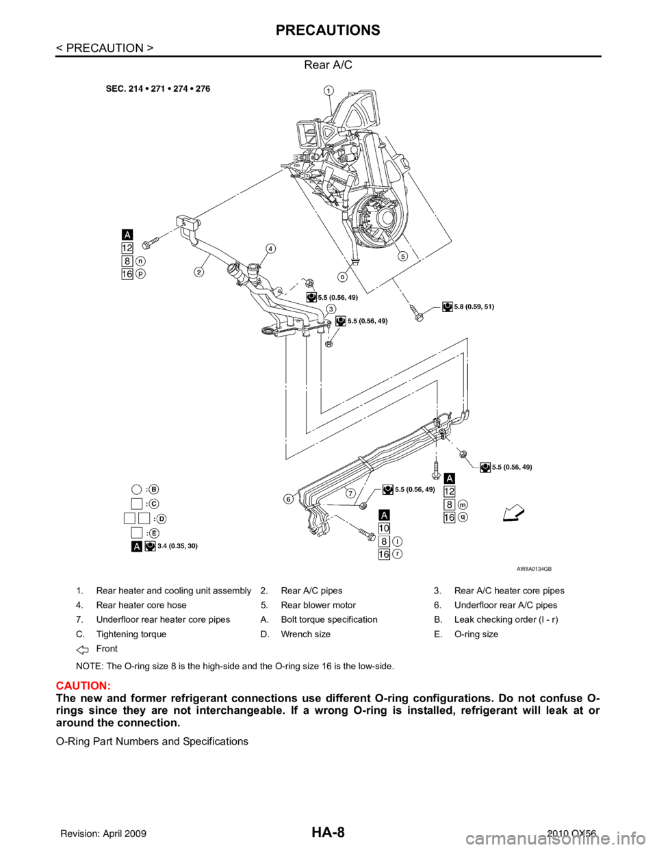
The new and former refrigerant connections use different O-ring configurations. Do not confuse O-
rings since they are not interchangeable. If a wrong O-ring is installed, refrigerant will leak at or
around the connection.
O-Ring Part Numbers and Specifications
AWIIA0134GB
1. Rear heater and cooling unit assembly 2. Rear A/C pipes 3. Rear A/C heater core pipes
4. Rear heater core hose 5. Rear blower motor6. Underfloor rear A/C pipes
7. Underfloor rear heater core pipes A. Bolt torque specification B. Leak checking order (l - r)
C. Tightening torque D. Wrench sizeE. O-ring size
Front
NOTE: The O-ring size 8 is the high-side and the O-ring size 16 is the low-side.
Revision: April 20092010 QX56