2010 INFINITI QX56 control arm
[x] Cancel search: control armPage 2087 of 4210

BCM (BODY CONTROL MODULE)EXL-111
< ECU DIAGNOSIS >
C
DE
F
G H
I
J
K
M A
B
EXL
N
O P
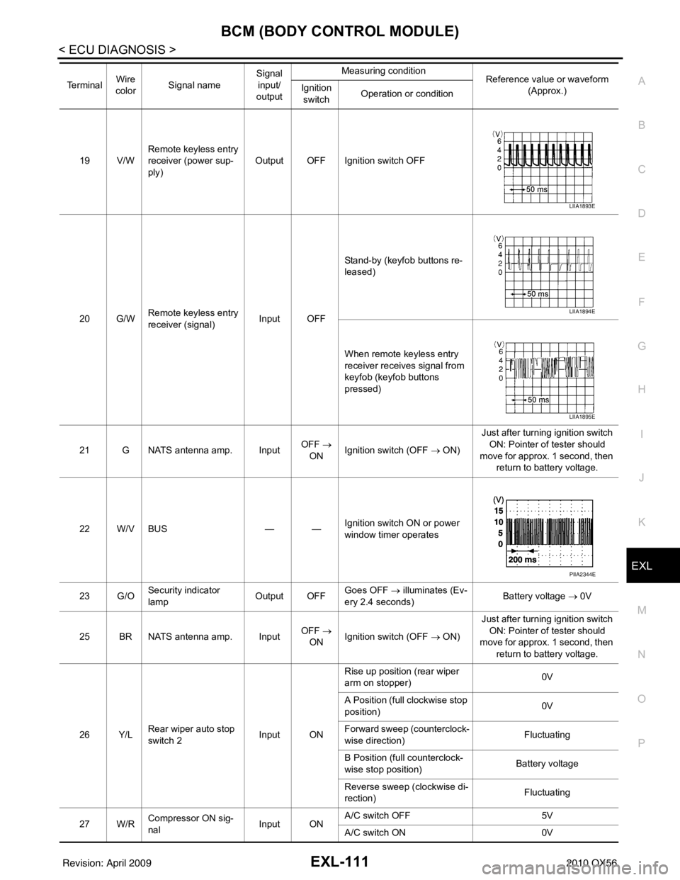
19 V/W Remote keyless entry
receiver (power sup-
ply) Output OFF Ignition switch OFF
20 G/W Remote keyless entry
receiver (signal) Input OFFStand-by (keyfob buttons re-
leased)
When remote keyless entry
receiver receives signal from
keyfob (keyfob buttons
pressed)
21 G NATS antenna amp. Input OFF
→
ON Ignition switch (OFF → ON) Just after turning ignition switch
ON: Pointer of tester should
move for approx. 1 second, then return to battery voltage.
22 W/V BUS — —Ignition switch ON or power
window timer operates
23 G/O Security indicator
lamp Output OFF
Goes OFF
→ illuminates (Ev-
ery 2.4 seconds) Battery voltage
→ 0V
25 BR NATS antenna amp. Input OFF
→
ON Ignition switch (OFF → ON) Just after turning ignition switch
ON: Pointer of tester should
move for approx. 1 second, then return to battery voltage.
26 Y/L Rear wiper auto stop
switch 2 Input ONRise up position (rear wiper
arm on stopper)
0V
A Position (full clockwise stop
position) 0V
Forward sweep (counterclock-
wise direction) Fluctuating
B Position (full counterclock-
wise stop position) Battery voltage
Reverse sweep (clockwise di-
rection) Fluctuating
27 W/R Compressor ON sig-
nal Input ONA/C switch OFF
5V
A/C switch ON 0V
Te r m i n a l
Wire
color Signal name Signal
input/
output Measuring condition
Reference value or waveform
(Approx.)
Ignition
switch Operation or condition
LIIA1893E
LIIA1894E
LIIA1895E
PIIA2344E
Revision: April 20092010 QX56
Page 2089 of 4210

BCM (BODY CONTROL MODULE)EXL-113
< ECU DIAGNOSIS >
C
DE
F
G H
I
J
K
M A
B
EXL
N
O P
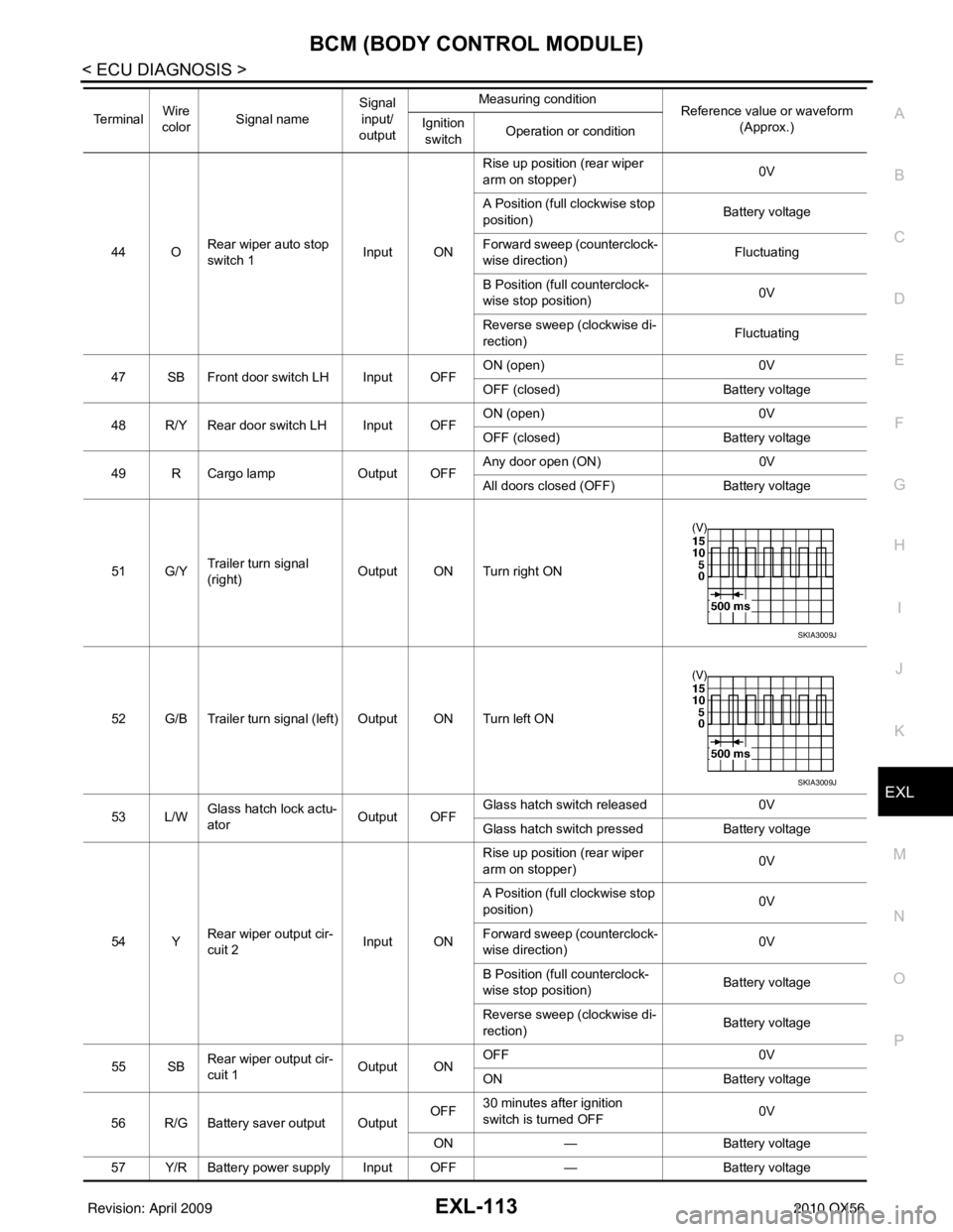
44 O Rear wiper auto stop
switch 1 Input ONRise up position (rear wiper
arm on stopper)
0V
A Position (full clockwise stop
position) Battery voltage
Forward sweep (counterclock-
wise direction) Fluctuating
B Position (full counterclock-
wise stop position) 0V
Reverse sweep (clockwise di-
rection) Fluctuating
47 SB Front door switch LH Input OFF ON (open)
0V
OFF (closed) Battery voltage
48 R/Y Rear door switch LH Input OFF ON (open)
0V
OFF (closed) Battery voltage
49 R Cargo lamp Output OFFAny door open (ON)
0V
All doors closed (OFF) Battery voltage
51 G/Y Trailer turn signal
(right) Output ON Turn right ON
52 G/B Trailer turn signal (left) Output ON Turn left ON
53 L/W Glass hatch lock actu-
ator
Output OFFGlass hatch switch released
0V
Glass hatch switch pressed Battery voltage
54 Y Rear wiper output cir-
cuit 2 Input ONRise up position (rear wiper
arm on stopper)
0V
A Position (full clockwise stop
position) 0V
Forward sweep (counterclock-
wise direction) 0V
B Position (full counterclock-
wise stop position) Battery voltage
Reverse sweep (clockwise di-
rection) Battery voltage
55 SB Rear wiper output cir-
cuit 1 Output ONOFF
0V
ON Battery voltage
56 R/G Battery saver output Output OFF
30 minutes after ignition
switch is turned OFF 0V
ON — Battery voltage
57 Y/R Battery power supply Input OFF —Battery voltage
Te r m i n a l
Wire
color Signal name Signal
input/
output Measuring condition
Reference value or waveform
(Approx.)
Ignition
switch Operation or condition
SKIA3009J
SKIA3009J
Revision: April 20092010 QX56
Page 2242 of 4210

TERMINOLOGYGI-19
< HOW TO USE THIS MANUAL >
C
DE
F
G H
I
J
K L
M B
GI
N
O P
***: Not applicable Transmission control module TCM A/T control unit
Turbocharger TC Turbocharger
Vehicle speed sensor VSS Vehicle speed sensor
Volume air flow sensor VAFS Air flow meter
Warm up oxidation catalyst WU-OC Catalyst
Warm up oxidation catalytic converter sys-
tem
WU-OC system ***
Warm up three way catalyst WU-TWC Catalyst
Warm up three way catalytic converter sys-
tem WU-TWC system
***
Wide open throttle position switch WOTP switchFull switch
NEW TERM
NEW ACRONYM /
ABBREVIATION OLD TERM
Revision: April 20092010 QX56
Page 2345 of 4210
![INFINITI QX56 2010 Factory Service Manual INSPECTION AND ADJUSTMENTHAC-5
< BASIC INSPECTION > [AUTOMATIC AIR CONDITIONER]
C
D
E
F
G H
J
K L
M A
B
HAC
N
O P
If NG, listen for sound of air mix door motor operat ion. If OK, go to trouble diagnos INFINITI QX56 2010 Factory Service Manual INSPECTION AND ADJUSTMENTHAC-5
< BASIC INSPECTION > [AUTOMATIC AIR CONDITIONER]
C
D
E
F
G H
J
K L
M A
B
HAC
N
O P
If NG, listen for sound of air mix door motor operat ion. If OK, go to trouble diagnos](/manual-img/42/57032/w960_57032-2344.png)
INSPECTION AND ADJUSTMENTHAC-5
< BASIC INSPECTION > [AUTOMATIC AIR CONDITIONER]
C
D
E
F
G H
J
K L
M A
B
HAC
N
O P
If NG, listen for sound of air mix door motor operat ion. If OK, go to trouble diagnosis procedure for HAC-108,
"Component Function Check". If air mix door motor appears to be malfunctioning, go to HAC-31, "Air Mix Door
Motor (Driver) Component Function Check".
If OK, continue the check.
CHECKING TEMPERATURE INCREASE
1. Rotate temperature control dial clockwise (drive or passenger) until 32 °C (90° F) is displayed.
2. Check for hot air at appropriate discharge air outlets.
If NG, listen for sound of air mix door motor operat ion. If OK, go to trouble diagnosis procedure for HAC-116,
"Component Function Check". If air mix door motor appears to be malfunctioning, go to HAC-31, "Air Mix Door
Motor (Driver) Component Function Check".
If OK, continue with next check.
CHECK A/C SWITCH
1. Press A/C switch when AUTO switch is ON, or in manual mode.
2. A/C switch indicator will turn ON. • Confirm that the compressor clutch engages (sound or visual inspection).
NOTE:
If current mode setting is DEF or D/F, compre ssor clutch will already be engaged and cannot be turned off.
If NG, go to trouble diagnosis procedure for HAC-68, "
Magnet Clutch Diagnosis Procedure".
If OK, continue with next check.
CHECKING AUTO MODE
1. Press AUTO switch.
2. Display should indicate AUTO.
• If ambient temperature is warm, and selected temperat ure is cool, confirm that the compressor clutch
engages (sound or visual inspection). (Discharge air and blower speed will depend on ambient, in-vehi-
cle, and set temperatures.)
If NG, go to trouble diagnosis procedure for HAC-87, "
A/C Auto Amp Power and Ground Diagnosis Proce-
dure", then if necessary, trouble diagnosis procedure for HAC-68, "Magnet Clutch Diagnosis Procedure".
If all operational checks are OK (symptom cannot be duplicated), go to malfunction Simulation Tests in HAC-
3, "How to Perform Trouble Diagnosis For Quick And Accurate Repair" and perform tests as outlined to simu-
late driving conditions environment. If symptom appears. Refer to HAC-107, "
SymptomMatrixChart", and
perform applicable troubl e diagnosis procedures.
Operational Check (Rear)INFOID:0000000005147670
The purpose of the operational check is to confirm that the system operates properly.
CHECKING REAR BLOWER MOTOR
1. Turn the ignition switch ON.
2. Rotate rear air control (front) blower control dial to low speed.
3. Rotate the blower control dial clockwise and continue checking blower speed until all speeds are checked.
4. Leave blower on maximum speed.
5. Press the REAR CTRL switch from the rear air control (front).
6. Rotate rear air control (rear) blower control dial to low speed.
7. Rotate the blower control dial clockwise and continue checking blower speed until all speeds are checked.
8. Leave blower on maximum speed.
If NG, go to trouble diagnosis procedure for HAC-53, "
Rear Blower Motor Component Function Check".
If OK, continue with next check.
CHECKING REAR DISCHARGE AIR
Conditions : Engine running and at normal operating temperature
Revision: April 20092010 QX56
Page 2456 of 4210
![INFINITI QX56 2010 Factory Service Manual HAC-116
< SYMPTOM DIAGNOSIS >[AUTOMATIC AIR CONDITIONER]
INSUFFICIENT HEATING
INSUFFICIENT HEATING
Component Function CheckINFOID:0000000005147739
SYMPTOM: Insufficient heating
INSPECTION FLOW
1.CONFI INFINITI QX56 2010 Factory Service Manual HAC-116
< SYMPTOM DIAGNOSIS >[AUTOMATIC AIR CONDITIONER]
INSUFFICIENT HEATING
INSUFFICIENT HEATING
Component Function CheckINFOID:0000000005147739
SYMPTOM: Insufficient heating
INSPECTION FLOW
1.CONFI](/manual-img/42/57032/w960_57032-2455.png)
HAC-116
< SYMPTOM DIAGNOSIS >[AUTOMATIC AIR CONDITIONER]
INSUFFICIENT HEATING
INSUFFICIENT HEATING
Component Function CheckINFOID:0000000005147739
SYMPTOM: Insufficient heating
INSPECTION FLOW
1.CONFIRM SYMPTOM BY PERFORMING OPER
ATIONAL CHECK - TEMPERATURE INCREASE
1. Press the AUTO switch.
2. Turn the temperature control dial (driver) clockwise until 32 °C (90° F) is displayed.
3. Check for hot air at discharge air outlets.
Can this symptom be duplicated?
YES >> GO TO 2.
NO >> Perform complete system operational check. Refer to HAC-4, "
Operational Check (Front)".
2.CHECK FOR SERVICE BULLETINS
Check for any service bulletins.
>> GO TO 3.
3.PERFORM SELF-DIAGNOSIS
Perform self-diagnosis. Refer to HAC-23, "
A/C Auto Amp. Self-Diagnosis".
Is the inspection result normal?
YES >> GO TO 4.
NO >> Refer to HAC-24, "
A/C System Self-Diagnosis Code Chart".
4.CHECK ENGINE COOLING SYSTEM
1. Check for proper engine coolant level. Refer to CO-10, "
Inspection".
2. Check hoses for leaks or kinks.
3. Check radiator cap. Refer to CO-10, "
Inspection".
4. Check for air in cooling system.
>> GO TO 5.
5.CHECK AIR MIX DOOR OPERATION
Check the operation of the air mix door.
Is the inspection result normal?
YES >> GO TO 6.
NO >> Check the air mix door motor circuit. Refer to HAC-31, "
Air Mix Door Motor (Driver) Component
Function Check".
6.CHECK AIR DUCTS
Check for disconnected or leaking air ducts.
Is the inspection result normal?
YES >> GO TO 7.
NO >> Repair all disconnected or leaking air ducts.
7.CHECK HEATER HOSE TEMPERATURES
1. Start engine and warm it up to normal operating temperature.
2. Touch both the inlet and outlet heater hoses. The inlet hose should be hot and the outlet hose should be
warm.
Is the inspection result normal?
YES >> Hot inlet hose and a warm outlet hose: GO TO 8.
NO >> • Inlet hose cold: GO TO 11. • Both hoses warm: GO TO 9.
8.CHECK ENGINE COOLANT SYSTEM
Revision: April 20092010 QX56
Page 2532 of 4210

BCM (BODY CONTROL MODULE)INL-63
< ECU DIAGNOSIS >
C
DE
F
G H
I
J
K
M A
B
INL
N
O P
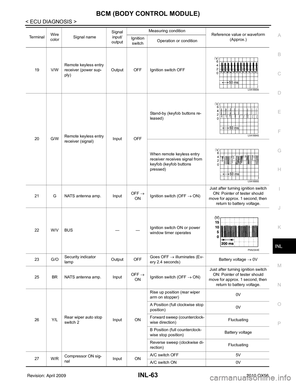
19 V/W Remote keyless entry
receiver (power sup-
ply) Output OFF Ignition switch OFF
20 G/W Remote keyless entry
receiver (signal) Input OFFStand-by (keyfob buttons re-
leased)
When remote keyless entry
receiver receives signal from
keyfob (keyfob buttons
pressed)
21 G NATS antenna amp. Input OFF
→
ON Ignition switch (OFF → ON) Just after turning ignition switch
ON: Pointer of tester should
move for approx. 1 second, then return to battery voltage.
22 W/V BUS — —Ignition switch ON or power
window timer operates
23 G/O Security indicator
lamp Output OFF
Goes OFF
→ illuminates (Ev-
ery 2.4 seconds) Battery voltage
→ 0V
25 BR NATS antenna amp. Input OFF
→
ON Ignition switch (OFF → ON) Just after turning ignition switch
ON: Pointer of tester should
move for approx. 1 second, then return to battery voltage.
26 Y/L Rear wiper auto stop
switch 2 Input ONRise up position (rear wiper
arm on stopper)
0V
A Position (full clockwise stop
position) 0V
Forward sweep (counterclock-
wise direction) Fluctuating
B Position (full counterclock-
wise stop position) Battery voltage
Reverse sweep (clockwise di-
rection) Fluctuating
27 W/R Compressor ON sig-
nal Input ONA/C switch OFF
5V
A/C switch ON 0V
Te r m i n a l
Wire
color Signal name Signal
input/
output Measuring condition
Reference value or waveform
(Approx.)
Ignition
switch Operation or condition
LIIA1893E
LIIA1894E
LIIA1895E
PIIA2344E
Revision: April 20092010 QX56
Page 2534 of 4210

BCM (BODY CONTROL MODULE)INL-65
< ECU DIAGNOSIS >
C
DE
F
G H
I
J
K
M A
B
INL
N
O P
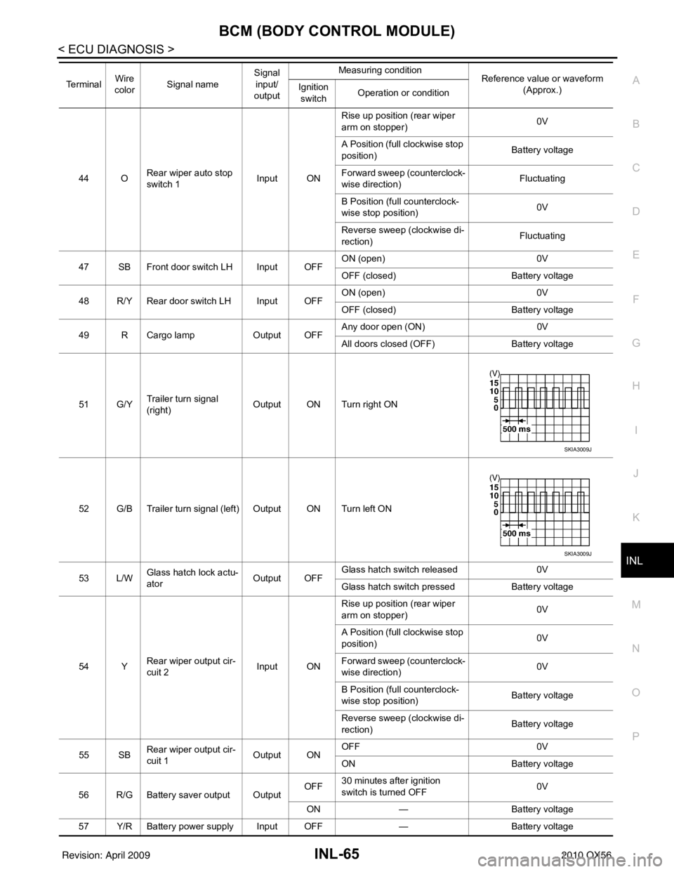
44 O Rear wiper auto stop
switch 1 Input ONRise up position (rear wiper
arm on stopper)
0V
A Position (full clockwise stop
position) Battery voltage
Forward sweep (counterclock-
wise direction) Fluctuating
B Position (full counterclock-
wise stop position) 0V
Reverse sweep (clockwise di-
rection) Fluctuating
47 SB Front door switch LH Input OFF ON (open)
0V
OFF (closed) Battery voltage
48 R/Y Rear door switch LH Input OFF ON (open)
0V
OFF (closed) Battery voltage
49 R Cargo lamp Output OFFAny door open (ON)
0V
All doors closed (OFF) Battery voltage
51 G/Y Trailer turn signal
(right) Output ON Turn right ON
52 G/B Trailer turn signal (left) Output ON Turn left ON
53 L/W Glass hatch lock actu-
ator
Output OFFGlass hatch switch released
0V
Glass hatch switch pressed Battery voltage
54 Y Rear wiper output cir-
cuit 2 Input ONRise up position (rear wiper
arm on stopper)
0V
A Position (full clockwise stop
position) 0V
Forward sweep (counterclock-
wise direction) 0V
B Position (full counterclock-
wise stop position) Battery voltage
Reverse sweep (clockwise di-
rection) Battery voltage
55 SB Rear wiper output cir-
cuit 1 Output ONOFF
0V
ON Battery voltage
56 R/G Battery saver output Output OFF
30 minutes after ignition
switch is turned OFF 0V
ON — Battery voltage
57 Y/R Battery power supply Input OFF —Battery voltage
Te r m i n a l
Wire
color Signal name Signal
input/
output Measuring condition
Reference value or waveform
(Approx.)
Ignition
switch Operation or condition
SKIA3009J
SKIA3009J
Revision: April 20092010 QX56
Page 2644 of 4210
![INFINITI QX56 2010 Factory Service Manual LAN-46
< FUNCTION DIAGNOSIS >[CAN]
CAN COMMUNICATION SYSTEM
NOTE:
CAN data of the air bag diagnosis sensor unit is not us
ed by usual service work, thus it is omitted.
Tire pressure data signal R T
T INFINITI QX56 2010 Factory Service Manual LAN-46
< FUNCTION DIAGNOSIS >[CAN]
CAN COMMUNICATION SYSTEM
NOTE:
CAN data of the air bag diagnosis sensor unit is not us
ed by usual service work, thus it is omitted.
Tire pressure data signal R T
T](/manual-img/42/57032/w960_57032-2643.png)
LAN-46
< FUNCTION DIAGNOSIS >[CAN]
CAN COMMUNICATION SYSTEM
NOTE:
CAN data of the air bag diagnosis sensor unit is not us
ed by usual service work, thus it is omitted.
Tire pressure data signal R T
Tire pressure signal R TR
Turn indicator signal TR
Buzzer output signal TR
Door lock/unlock request signal RT
Hazard request signal RT
Hazard warning lamp request signal RT
Ignition knob switch signal RT
KEY warning signal TR
LOCK warning signal TR
Panic alarm request signal RT
Power window open request signal RT
1st position switch signal R T
4th position switch signal R T
Distance to empty signal RT
Fuel level low warning signal RT
Fuel level sensor signal R T
Parking brake switch signal RT
Seat belt buckle switch signal RT
Stop lamp switch signal R T
Tow mode switch signal R T
Vehicle speed signal RRR RRR R T
RRRT
Steering angle sensor signal TR
ABS malfunction signal RT
ABS warning lamp signal RT
Brake pressure sensor signal RT
Brake warning lamp signal RT
SLIP indicator lamp signal RT
TCS malfunction signal RT
VDC malfunction signal RT
VDC OFF indicator lamp signal RRT
VDC operation signal RT
Front wiper stop position signal RT
High beam status signal R T
Hood switch signal RT
Low beam status signal R T
Rear window defogger control signal R RT
Signal name/Connecting unit
ECM
TCM
LASER ICC
ADP
AV
BCM
HVAC I-KEY M&A
STRG 4WDABS
IPDM-E
Revision: April 20092010 QX56