2010 INFINITI QX56 Power window
[x] Cancel search: Power windowPage 2087 of 4210
BCM (BODY CONTROL MODULE)EXL-111
< ECU DIAGNOSIS >
C
DE
F
G H
I
J
K
M A
B
EXL
N
O P
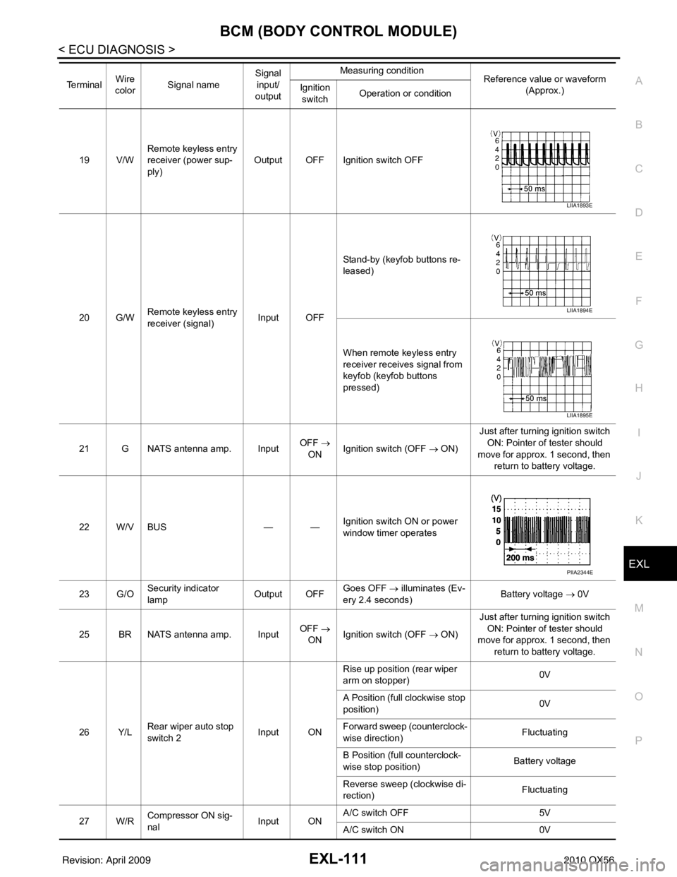
19 V/W Remote keyless entry
receiver (power sup-
ply) Output OFF Ignition switch OFF
20 G/W Remote keyless entry
receiver (signal) Input OFFStand-by (keyfob buttons re-
leased)
When remote keyless entry
receiver receives signal from
keyfob (keyfob buttons
pressed)
21 G NATS antenna amp. Input OFF
→
ON Ignition switch (OFF → ON) Just after turning ignition switch
ON: Pointer of tester should
move for approx. 1 second, then return to battery voltage.
22 W/V BUS — —Ignition switch ON or power
window timer operates
23 G/O Security indicator
lamp Output OFF
Goes OFF
→ illuminates (Ev-
ery 2.4 seconds) Battery voltage
→ 0V
25 BR NATS antenna amp. Input OFF
→
ON Ignition switch (OFF → ON) Just after turning ignition switch
ON: Pointer of tester should
move for approx. 1 second, then return to battery voltage.
26 Y/L Rear wiper auto stop
switch 2 Input ONRise up position (rear wiper
arm on stopper)
0V
A Position (full clockwise stop
position) 0V
Forward sweep (counterclock-
wise direction) Fluctuating
B Position (full counterclock-
wise stop position) Battery voltage
Reverse sweep (clockwise di-
rection) Fluctuating
27 W/R Compressor ON sig-
nal Input ONA/C switch OFF
5V
A/C switch ON 0V
Te r m i n a l
Wire
color Signal name Signal
input/
output Measuring condition
Reference value or waveform
(Approx.)
Ignition
switch Operation or condition
LIIA1893E
LIIA1894E
LIIA1895E
PIIA2344E
Revision: April 20092010 QX56
Page 2090 of 4210

EXL-114
< ECU DIAGNOSIS >
BCM (BODY CONTROL MODULE)
58 W/R Optical sensorInput ONWhen optical sensor is illumi-
nated
3.1V or more
When optical sensor is not illu-
minated 0.6V or less
59 G Front door lock as-
sembly LH actuator
(unlock) Output OFF
OFF (neutral)
0V
ON (unlock) Battery voltage
60 G/B Turn signal (left) Output ON Turn left ON
61 G/Y Turn signal (right) Output ON Turn right ON
62 R/W Step lamp LH and RH Output OFF ON (any door open)
0V
OFF (all doors closed) Battery voltage
63 L Interior room/map
lamp Output OFFAny door
switchON (open)
0V
OFF (closed) Battery voltage
65 V All door lock actuators
(lock) Output OFFOFF (neutral)
0V
ON (lock) Battery voltage
66 G/Y Front door lock actua-
tor RH, rear door lock
actuators LH/RH and
back door lock actua-
tor (unlock) Output OFF
OFF (neutral)
0V
ON (unlock) Battery voltage
67 B Ground Input ON—0V
68 W/L Power window power
supply (RAP) Output —Ignition switch ON
Battery voltage
Within 45 seconds after igni-
tion switch OFF Battery voltage
More than 45 seconds after ig-
nition switch OFF 0V
When front door LH or RH is
open or power window timer
operates 0V
69 W/R Power window power
supply
Output —
—Battery voltage
70 W/B Battery power supply Input OFF —Battery voltage
Te r m i n a l
Wire
color Signal name Signal
input/
output Measuring condition
Reference value or waveform
(Approx.)
Ignition
switch Operation or condition
SKIA3009J
SKIA3009J
Revision: April 20092010 QX56
Page 2105 of 4210

IPDM E/R (INTELLIGENT POWER DISTRIBUTION MODULE ENGINE ROOM)
EXL-129
< ECU DIAGNOSIS >
C
D E
F
G H
I
J
K
M A
B
EXL
N
O P
*: When horn reminder is ON 60 B/W
Rear window defog-
ger relay
OutputON or
START Rear defogger switch ON
Battery voltage
Rear defogger switch OFF 0V
61 BR Fuse 32
(With trailer tow) Output OFF
—Battery voltage
Te r m i n a l
Wire
color Signal name Signal
input/
output Measuring condition
Reference value(Approx.)
Igni-
tion
switch Operation or condition
Revision: April 20092010 QX56
Page 2110 of 4210

EXL-134
< ECU DIAGNOSIS >
IPDM E/R (INTELLIGENT POWER DISTRIBUTION MODULE ENGINE ROOM)
If No CAN Communication Is Available With BCM
IGNITION RELAY MALFUNCTION DETECTION FUNCTION
• IPDM E/R monitors the voltage at the contact circuit and excitation coil circuit of the ignition relay inside it.
• IPDM E/R judges the ignition relay error if the voltage differs between the contact circuit and the excitation
coil circuit.
• If the ignition relay cannot turn OFF due to contact seizure, it activates the tail lamp relay for 10 minutes to alert the user to the ignition relay malfunction when the ignition switch is turned OFF.
NOTE:
The tail lamp turns OFF when the ignition switch is turned ON.
FRONT WIPER CONTROL
IPDM E/R detects front wiper stop posit ion by a front wiper auto stop signal.
When a front wiper auto stop signal is in the conditions listed below, IPDM E/R stops power supply to wiper
after repeating a front wiper 10 second activation and 20 second stop five times.
NOTE:
This operation status can be confirmed on the IPDM E/R “DATA MONITOR” that displays “Block” for the item
“WIP PROT” while the wiper is stopped.
STARTER MOTOR PROTECTION FUNCTION
IPDM E/R turns OFF the starter control relay to protect the starter motor when the starter control relay remains
active for 90 seconds.
Control part Fail-safe in operation
Cooling fan • Turns ON the cooling fan relay when the ignition switch is turned ON
• Turns OFF the cooling fan relay when the ignition switch is turned OFF
Control part
Fail-safe in operation
Headlamp • Turns ON the headlamp low relay when the ignition switch is turned ON
• Turns OFF the headlamp low relay when the ignition switch is turned OFF
• Headlamp high LH/RH relays OFF
•Parking lamps
• License plate lamps
• Tail lamps • Turns ON the tail lamp relay when the ignition switch is turned ON
• Turns OFF the tail lamp relay when the ignition switch is turned OFF
Front wiper • The status just before activation of fail-safe control is maintained until the ignition
switch is turned OFF while the front wiper is operating at LO or HI speed.
• The wiper is operated at LO speed until the ignition switch is turned OFF if the fail- safe control is activated while the front wipe r is set in the INT mode and the front wiper
motor is operating.
Rear window defogger Rear window defogger relay OFF
A/C compressor A/C relay OFF
Front fog lamps Front fog lamp relay OFF
Ignition switch Ignition relayTail lamp relay
ON ON —
OFF OFF —
Ignition switchFront wiper switch Auto stop signal
ON OFF
Front wiper stop position signal cannot be
input 10 seconds.
ON The signal does not change for 10 seconds.
Revision: April 20092010 QX56
Page 2282 of 4210
WINDSHIELD GLASSGW-11
< ON-VEHICLE REPAIR >
C
DE
F
G H
I
J
L
M A
B
GW
N
O P
ON-VEHICLE REPAIR
WINDSHIELD GLASS
Removal and InstallationINFOID:0000000005147159
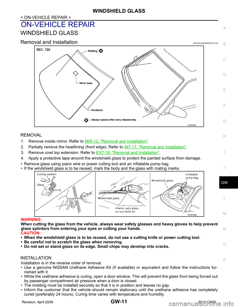
REMOVAL
1. Remove inside mirror. Refer to MIR-12, "Removal and Installation".
2. Partially remove the headlining (front edge). Refer to INT-17, "
Removal and Installation".
3. Remove cowl top extension. Refer to EXT-18, "
Removal and Installation".
4. Apply a protective tape around the windshield gl ass to protect the painted surface from damage.
• Remove glass using piano wire or power cutting tool and an inflatable pump bag.
• If the windshield glass is to be reused, mark the body and the glass with mating marks.
WARNING:
When cutting the glass from the vehicle, always wear safety glasses and heavy gloves to help prevent
glass splinters from entering your eyes or cutting your hands.
CAUTION:
• When the windshield glass is to be reused, do not use a cutting knife or power cutting tool.
• Be careful not to scratch the glass when removing.
• Do not set or stand glass on its ed ge. Small chips may develop into cracks.
INSTALLATION
Installation is in the reverse order of removal.
• Use a genuine NISSAN Urethane Adhesive Kit (if availabl e) or equivalent and follow the instructions fur-
nished with it.
• While the urethane adhesive is curing, open a door window . This will prevent the glass from being forced out
by passenger compartment air pressure when a door is closed.
• The molding must be installed securely so that it is in position and leaves no gap.
• Inform the customer that the vehicle should rema in stationary until the urethane adhesive has completely
cured (preferably 24 hours). Curing time varies with temperature and humidity.
LIIA0652E
PIIA0186E
Revision: April 20092010 QX56
Page 2286 of 4210
FRONT DOOR GLASS AND REGULATORGW-15
< ON-VEHICLE REPAIR >
C
DE
F
G H
I
J
L
M A
B
GW
N
O P
FRONT DOOR GLASS AND REGULATOR
Removal and InstallationINFOID:0000000005147161
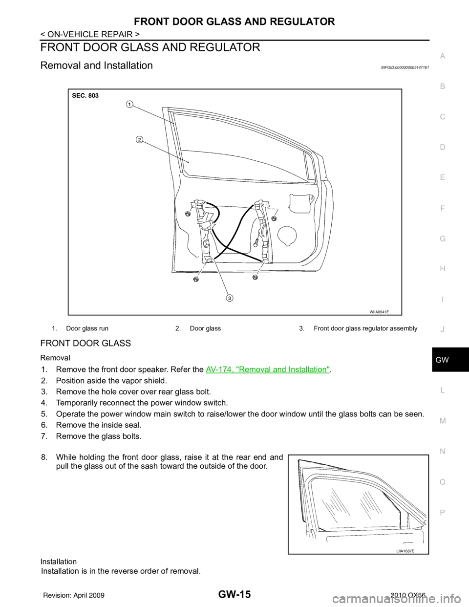
FRONT DOOR GLASS
Removal
1. Remove the front door speaker. Refer the AV-174, "Removal and Installation".
2. Position aside the vapor shield.
3. Remove the hole cover over rear glass bolt.
4. Temporarily reconnect the power window switch.
5. Operate the power window main switch to raise/lo wer the door window until the glass bolts can be seen.
6. Remove the inside seal.
7. Remove the glass bolts.
8. While holding the front door glass, raise it at the rear end and pull the glass out of the sash toward the outside of the door.
Installation
Installation is in the reverse order of removal.
1. Door glass run 2. Door glass3. Front door glass regulator assembly
WIIA0941E
LIIA1687E
Revision: April 20092010 QX56
Page 2287 of 4210
GW-16
< ON-VEHICLE REPAIR >
FRONT DOOR GLASS AND REGULATOR
Fitting Inspection
• Check that the glass is securely fit into the glass run groove.
• Lower the glass slightly [approximately 10 to 20 mm (0.39 to 0.79 in)] and check that the clearance to the
sash is parallel. If the clearance between the glass and sash is not parallel, loosen the regulator bolts, guide
rail bolts, and glass and guide rail bolts to correct the glass position.
FRONT DOOR GLASS REGULATOR
Removal
1. Remove the front door finisher. Refer the INT-11, "Removal and Installation".
2. Position aside the vapor shield.
3. Remove the hole cover over rear glass bolt.
4. Temporarily reconnect the power window switch.
5. Operate the power window main switch to raise/ lower the door window until the glass bolts can be seen.
6. Remove the glass bolts.
7. Raise the front door glass and hold it in place with suitable tool.
8. Disconnect the harness connector fr om the regulator assembly.
9. Remove the bolts and the regulator assembly.
Installation
1. Install the regulator assembly.
2. Reposition the vapor shield.
3. Connect the harness connector to the regulator assembly.
4. Align the glass and install the glass bolts.
5. Reset the limit switch. Follow the "Setting of Limit Switch" procedure.
6. Install front door finisher. Refer to INT-11, "
Removal and Installation".
SETTING AFTER INSTALLATION
Setting of Limit Switch
If any of the following work has been done, set the limit switch (integrated in the motor).
• Removal and installation of the regulator.
• Removal and installation of the motor from the regulator.
• Removal and installation of the glass.
• Removal and installation of the glass run.
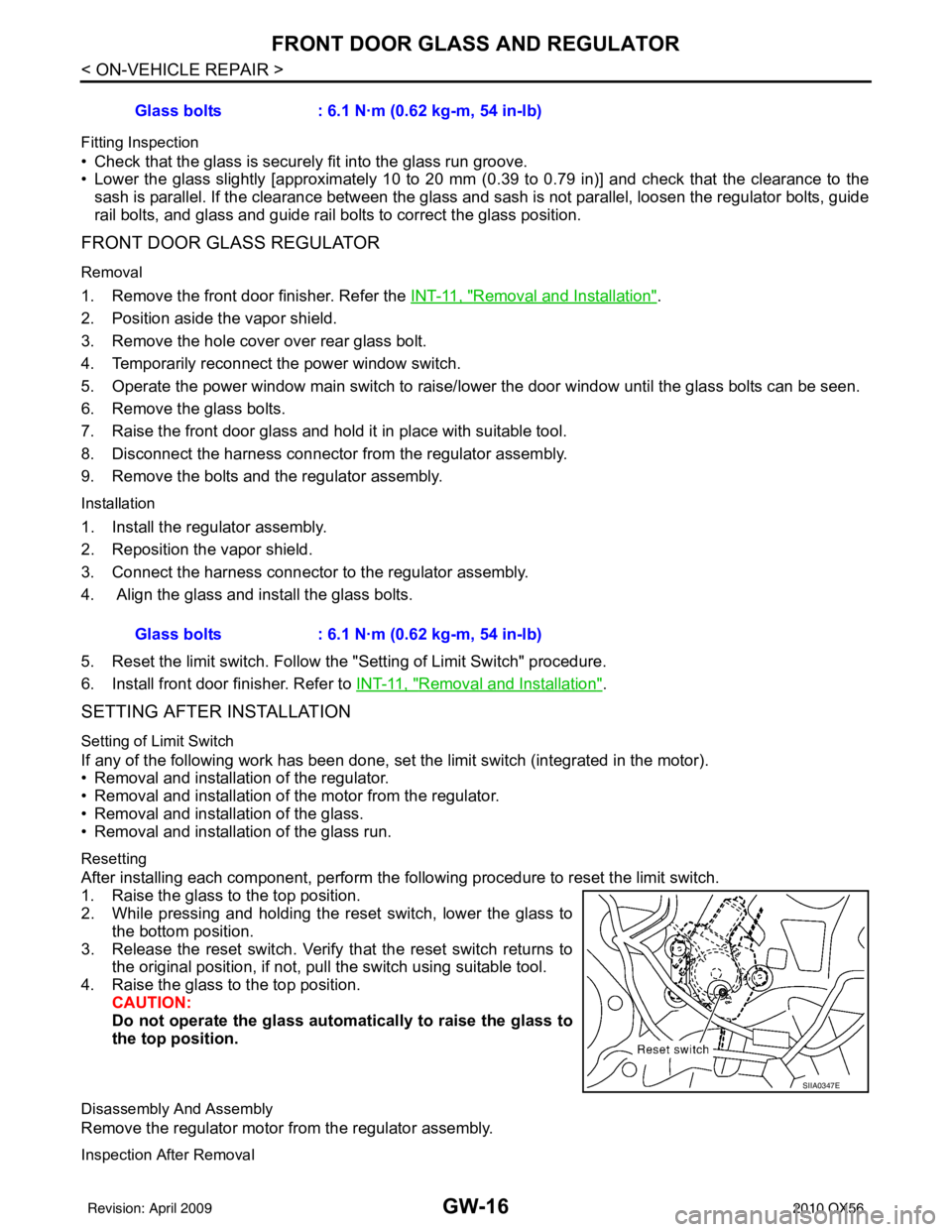
Resetting
After installing each component, perform the following procedure to reset the limit switch.
1. Raise the glass to the top position.
2. While pressing and holding the reset switch, lower the glass to
the bottom position.
3. Release the reset switch. Verify that the reset switch returns to the original position, if not, pu ll the switch using suitable tool.
4. Raise the glass to the top position. CAUTION:
Do not operate the glass automatically to raise the glass to
the top position.
Disassembly And Assembly
Remove the regulator motor from the regulator assembly.
Inspection After Removal
Glass bolts : 6.1 N·m (0.62 kg-m, 54 in-lb)
Glass bolts : 6.1 N·m (0.62 kg-m, 54 in-lb)
SIIA0347E
Revision: April 20092010 QX56
Page 2289 of 4210
GW-18
< ON-VEHICLE REPAIR >
REAR DOOR GLASS AND REGULATOR
REAR DOOR GLASS AND REGULATOR
Removal and InstallationINFOID:0000000005147162
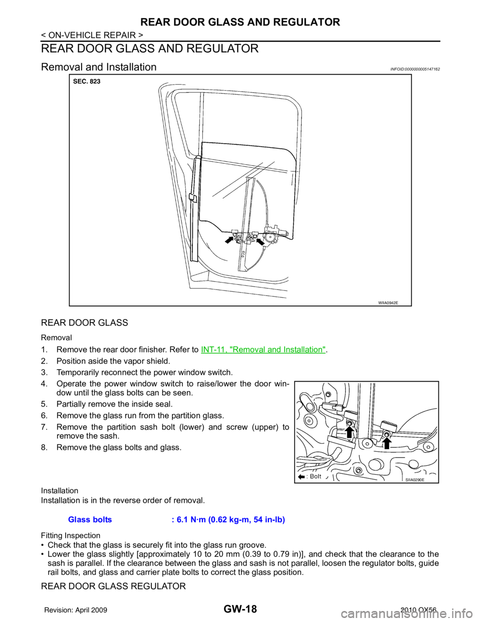
REAR DOOR GLASS
Removal
1. Remove the rear door finisher. Refer to INT-11, "Removal and Installation".
2. Position aside the vapor shield.
3. Temporarily reconnect the power window switch.
4. Operate the power window switch to raise/lower the door win- dow until the glass bolts can be seen.
5. Partially remove the inside seal.
6. Remove the glass run from the partition glass.
7. Remove the partition sash bolt (lower) and screw (upper) to remove the sash.
8. Remove the glass bolts and glass.
Installation
Installation is in the reverse order of removal.
Fitting Inspection
• Check that the glass is securely fit into the glass run groove.
• Lower the glass slightly [approximately 10 to 20 mm (0.39 to 0.79 in)], and check that the clearance to the
sash is parallel. If the clearance between the glass and sash is not parallel, loosen the regulator bolts, guide
rail bolts, and glass and carrier plate bolts to correct the glass position.
REAR DOOR GLASS REGULATOR
WIIA0942E
SIIA0290E
Glass bolts : 6.1 N·m (0.62 kg-m, 54 in-lb)
Revision: April 20092010 QX56