2010 INFINITI QX56 ECU
[x] Cancel search: ECUPage 2274 of 4210

SQUEAK AND RATTLE TROUBLE DIAGNOSISGW-3
< SYMPTOM DIAGNOSIS >
C
DE
F
G H
I
J
L
M A
B
GW
N
O P
If possible, drive the vehicle with the customer until the noise is duplicated. Note any additional information on
the Diagnostic Worksheet regarding the conditions or lo cation of the noise. This information can be used to
duplicate the same conditions when you confirm the repair.
If the noise can be duplicated easily during the test drive, to help identify the source of the noise, try to dupli-
cate the noise with the vehicle stopped by doing one or all of the following:
1) Close a door.
2) Tap or push/pull around the area where the noise appears to be coming from.
3) Rev the engine.
4) Use a floor jack to recreate vehicle “twist”.
5) At idle, apply engine load (electrical load, half- clutch on M/T model, drive position on A/T model).
6) Raise the vehicle on a hoist and hit a tire with a rubber hammer.
• Drive the vehicle and attempt to duplicate the conditions the customer states exist when the noise occurs.
• If it is difficult to duplicate the noise, drive the vehicle slowly on an undulating or rough road to stress the vehicle body.
CHECK RELATED SERVICE BULLETINS
After verifying the customer concern or symptom, check ASIST for Technical Service Bulletins (TSBs) related
to that concern or symptom.
If a TSB relates to the symptom, follow the procedure to repair the noise.
LOCATE THE NOISE AND IDENTIFY THE ROOT CAUSE
1. Narrow down the noise to a general area.To help pinpoint the source of the noise, use a listening tool (Chassis Ear: J-39570, Engine Ear: J-39565 and mechanic's stethoscope).
2. Narrow down the noise to a more specific area and identify the cause of the noise by:
• removing the components in the area that you suspect the noise is coming from. Do not use too much force when removing clips and fasteners, otherwise clips and fasteners can be broken
or lost during the repair, resulting in the creation of new noise.
• tapping or pushing/pulling the component that you suspect is causing the noise.
Do not tap or push/pull the component with excessive force, otherwise the noise will be eliminated only tem-
porarily.
• feeling for a vibration with your hand by touching the component(s) that you suspect is (are) causing the
noise.
• placing a piece of paper between components that you suspect are causing the noise.
• looking for loose components and contact marks. Refer to GW-4, "
Generic Squeak and Rattle Troubleshooting".
REPAIR THE CAUSE
• If the cause is a loose component, tighten the component securely.
• If the cause is insufficient clearance between components:
- separate components by repositioning or loos ening and retightening the component, if possible.
- insulate components with a suitable insulator such as urethane pads, foam blocks, felt cloth tape or urethane tape. A NISSAN Squeak and Rattle Kit (J-43980) is available through your authorized NISSAN Parts Depart-
ment.
CAUTION:
Do not use excessive force as many components are constructed of plastic and may be damaged.
Always check with the Parts Department for the latest parts information.
The following materials are contained in the NISSAN Squeak and Rattle Kit (J-43980). Each item can be
ordered separately as needed.
URETHANE PADS [1.5 mm (0.059 in) thick]
Insulates connectors, harness, etc.
76268-9E005: 100 ×135 mm (3.94 ×5.31 in)/76884-71L01: 60 ×85 mm (2.36× 3.35 in)/76884-71L02: 15× 25
mm (0.59 ×0.98 in)
INSULATOR (Foam blocks)
Insulates components from contact. Can be used to fill space behind a panel.
73982-9E000: 45 mm (1.77 in) thick, 50× 50 mm (1.97×1.97 in)/73982-50Y00: 10 mm (0.39 in) thick,
50× 50 mm (1.97 ×1.97 in)
INSULATOR (Light foam block)
80845-71L00: 30 mm (1.18 in) thick, 30 ×50 mm (1.18 ×1.97 in)
FELT CLOTH TAPE
Used to insulate where movement does not occu r. Ideal for instrument panel applications.
Revision: April 20092010 QX56
Page 2276 of 4210

SQUEAK AND RATTLE TROUBLE DIAGNOSISGW-5
< SYMPTOM DIAGNOSIS >
C
DE
F
G H
I
J
L
M A
B
GW
N
O P
2. Trunk lid striker out of adjustment
3. The trunk lid torsion bars knocking together
4. A loose license plate or bracket
Most of these incidents can be repaired by adjusting, se curing or insulating the item(s) or component(s) caus-
ing the noise.
SUNROOF/HEADLINING
Noises in the sunroof/headlining area can often be traced to one of the following:
1. Sunroof lid, rail, linkage or seals making a rattle or light knocking noise
2. Sun visor shaft shaking in the holder
3. Front or rear windshield touching headliner and squeaking
Again, pressing on the components to stop the noise while duplicating the conditions can isolate most of these
incidents. Repairs usually consist of insulating with felt cloth tape.
OVERHEAD CONSOLE (FRONT AND REAR)
Overhead console noises are often caused by the cons ole panel clips not being engaged correctly. Most of
these incidents are repaired by pushing up on the c onsole at the clip locations until the clips engage.
In addition look for:
1. Loose harness or harness connectors.
2. Front console map/reading lamp lense loose.
3. Loose screws at console attachment points.
SEATS
When isolating seat noise it's important to note the position the seat is in and the load placed on the seat when
the noise is present. These conditions should be duplicated when verifying and isolating the cause of the
noise.
Cause of seat noise include:
1. Headrest rods and holder
2. A squeak between the seat pad cushion and frame
3. The rear seatback lock and bracket
These noises can be isolated by moving or pressing on the suspected components while duplicating the con-
ditions under which the noise occurs. Most of thes e incidents can be repaired by repositioning the component
or applying urethane tape to the contact area.
UNDERHOOD
Some interior noise may be caused by components under the hood or on the engine wall. The noise is then
transmitted into the passenger compartment.
Causes of transmitted underhood noise include:
1. Any component mounted to the engine wall
2. Components that pass through the engine wall
3. Engine wall mounts and connectors
4. Loose radiator mounting pins
5. Hood bumpers out of adjustment
6. Hood striker out of adjustment
These noises can be difficult to isolate since they cannot be reached from the interior of the vehicle. The best
method is to secure, move or insulate one component at a time and test drive the vehicle. Also, engine RPM
or load can be changed to isolate the noise. Repairs can usually be made by moving, adjusting, securing, or
insulating the component causing the noise.
Revision: April 20092010 QX56
Page 2282 of 4210

WINDSHIELD GLASSGW-11
< ON-VEHICLE REPAIR >
C
DE
F
G H
I
J
L
M A
B
GW
N
O P
ON-VEHICLE REPAIR
WINDSHIELD GLASS
Removal and InstallationINFOID:0000000005147159
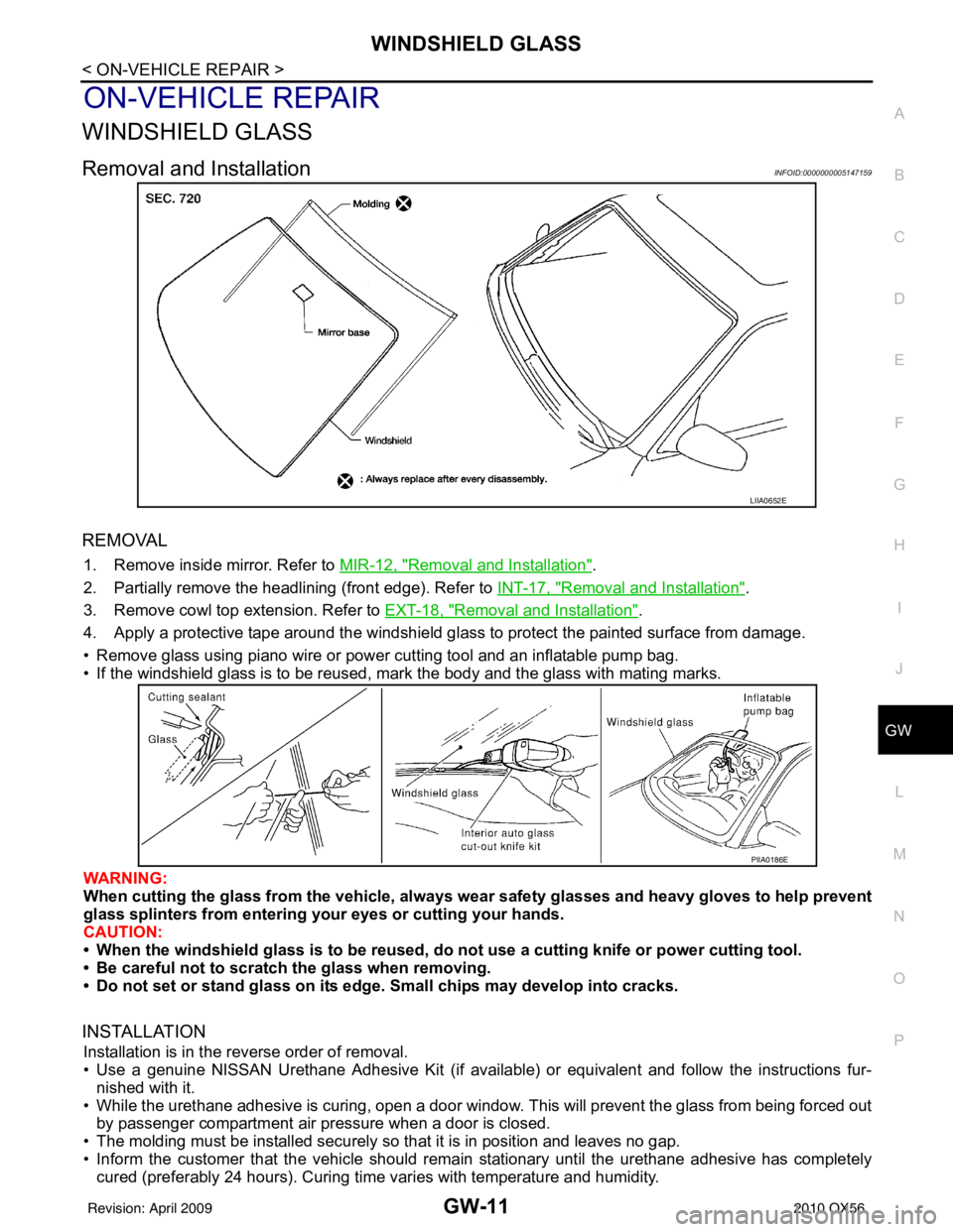
REMOVAL
1. Remove inside mirror. Refer to MIR-12, "Removal and Installation".
2. Partially remove the headlining (front edge). Refer to INT-17, "
Removal and Installation".
3. Remove cowl top extension. Refer to EXT-18, "
Removal and Installation".
4. Apply a protective tape around the windshield gl ass to protect the painted surface from damage.
• Remove glass using piano wire or power cutting tool and an inflatable pump bag.
• If the windshield glass is to be reused, mark the body and the glass with mating marks.
WARNING:
When cutting the glass from the vehicle, always wear safety glasses and heavy gloves to help prevent
glass splinters from entering your eyes or cutting your hands.
CAUTION:
• When the windshield glass is to be reused, do not use a cutting knife or power cutting tool.
• Be careful not to scratch the glass when removing.
• Do not set or stand glass on its ed ge. Small chips may develop into cracks.
INSTALLATION
Installation is in the reverse order of removal.
• Use a genuine NISSAN Urethane Adhesive Kit (if availabl e) or equivalent and follow the instructions fur-
nished with it.
• While the urethane adhesive is curing, open a door window . This will prevent the glass from being forced out
by passenger compartment air pressure when a door is closed.
• The molding must be installed securely so that it is in position and leaves no gap.
• Inform the customer that the vehicle should rema in stationary until the urethane adhesive has completely
cured (preferably 24 hours). Curing time varies with temperature and humidity.
LIIA0652E
PIIA0186E
Revision: April 20092010 QX56
Page 2287 of 4210

GW-16
< ON-VEHICLE REPAIR >
FRONT DOOR GLASS AND REGULATOR
Fitting Inspection
• Check that the glass is securely fit into the glass run groove.
• Lower the glass slightly [approximately 10 to 20 mm (0.39 to 0.79 in)] and check that the clearance to the
sash is parallel. If the clearance between the glass and sash is not parallel, loosen the regulator bolts, guide
rail bolts, and glass and guide rail bolts to correct the glass position.
FRONT DOOR GLASS REGULATOR
Removal
1. Remove the front door finisher. Refer the INT-11, "Removal and Installation".
2. Position aside the vapor shield.
3. Remove the hole cover over rear glass bolt.
4. Temporarily reconnect the power window switch.
5. Operate the power window main switch to raise/ lower the door window until the glass bolts can be seen.
6. Remove the glass bolts.
7. Raise the front door glass and hold it in place with suitable tool.
8. Disconnect the harness connector fr om the regulator assembly.
9. Remove the bolts and the regulator assembly.
Installation
1. Install the regulator assembly.
2. Reposition the vapor shield.
3. Connect the harness connector to the regulator assembly.
4. Align the glass and install the glass bolts.
5. Reset the limit switch. Follow the "Setting of Limit Switch" procedure.
6. Install front door finisher. Refer to INT-11, "
Removal and Installation".
SETTING AFTER INSTALLATION
Setting of Limit Switch
If any of the following work has been done, set the limit switch (integrated in the motor).
• Removal and installation of the regulator.
• Removal and installation of the motor from the regulator.
• Removal and installation of the glass.
• Removal and installation of the glass run.
Resetting
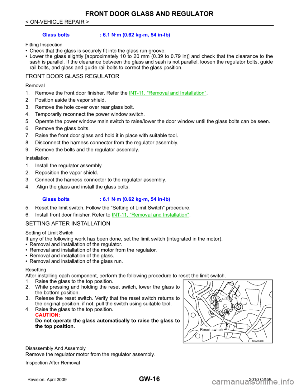
After installing each component, perform the following procedure to reset the limit switch.
1. Raise the glass to the top position.
2. While pressing and holding the reset switch, lower the glass to
the bottom position.
3. Release the reset switch. Verify that the reset switch returns to the original position, if not, pu ll the switch using suitable tool.
4. Raise the glass to the top position. CAUTION:
Do not operate the glass automatically to raise the glass to
the top position.
Disassembly And Assembly
Remove the regulator motor from the regulator assembly.
Inspection After Removal
Glass bolts : 6.1 N·m (0.62 kg-m, 54 in-lb)
Glass bolts : 6.1 N·m (0.62 kg-m, 54 in-lb)
SIIA0347E
Revision: April 20092010 QX56
Page 2289 of 4210

GW-18
< ON-VEHICLE REPAIR >
REAR DOOR GLASS AND REGULATOR
REAR DOOR GLASS AND REGULATOR
Removal and InstallationINFOID:0000000005147162
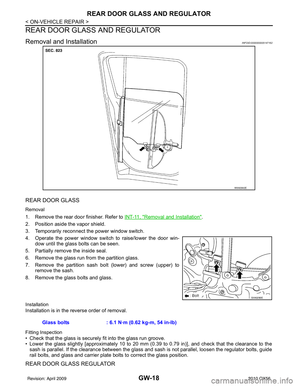
REAR DOOR GLASS
Removal
1. Remove the rear door finisher. Refer to INT-11, "Removal and Installation".
2. Position aside the vapor shield.
3. Temporarily reconnect the power window switch.
4. Operate the power window switch to raise/lower the door win- dow until the glass bolts can be seen.
5. Partially remove the inside seal.
6. Remove the glass run from the partition glass.
7. Remove the partition sash bolt (lower) and screw (upper) to remove the sash.
8. Remove the glass bolts and glass.
Installation
Installation is in the reverse order of removal.
Fitting Inspection
• Check that the glass is securely fit into the glass run groove.
• Lower the glass slightly [approximately 10 to 20 mm (0.39 to 0.79 in)], and check that the clearance to the
sash is parallel. If the clearance between the glass and sash is not parallel, loosen the regulator bolts, guide
rail bolts, and glass and carrier plate bolts to correct the glass position.
REAR DOOR GLASS REGULATOR
WIIA0942E
SIIA0290E
Glass bolts : 6.1 N·m (0.62 kg-m, 54 in-lb)
Revision: April 20092010 QX56
Page 2342 of 4210

HAC-2
Rear Air Control Component Function Check ........58
Air Mix Door Motor (Rear) Diagnosis Procedure ....59
Mode Door Motor (Rear) Diagnosis Procedure ......63
MAGNET CLUTCH ............................................68
System Description .............................................. ...68
Magnet Clutch Component Function Check ........ ...68
Magnet Clutch Diagnosis Procedure ................... ...68
WATER VALVE CIRCUIT ..................................73
Description ........................................................... ...73
Water Valve Diagnosis Procedure ..........................73
AMBIENT SENSOR ...........................................75
Component Description ....................................... ...75
Ambient Sensor Diagnosis Procedure ....................75
Ambient Sensor Component Inspection .................76
IN-VEHICLE SENSOR .......................................78
Component Description ....................................... ...78
In-Vehicle Sensor Diagnosis Procedure .................78
In-Vehicle Sensor Component Inspection ..............80
OPTICAL SENSOR ...........................................81
Component Description ..........................................81
Optical Sensor Diagnosis Procedure ......................81
INTAKE SENSOR ..............................................83
System Description .............................................. ...83
Intake Sensor Diagnosis Procedure .......................83
Intake Sensor Component Inspection ................. ...84
POWER SUPPLY AND GROUND CIRCUIT
FOR CONTROLLER ..........................................
86
Component Description ....................................... ...86
A/C Auto Amp. Component Function Check ..........86
A/C Auto Amp Power and Ground Diagnosis Pro-
cedure .................................................................. ...
87
ECU DIAGNOSIS .......................................89
AIR CONDITIONER CONTROL ..................... ...89
A/C Auto Amp. Terminals Reference Values ..........89
Wiring Diagram .................................................... ...91
SYMPTOM DIAGNOSIS ...........................107
AIR CONDITIONER CONTROL ..................... ..107
Symptom Matrix Chart ........................................ .107
INSUFFICIENT COOLING ................................108
Component Function Check ................................ .108
Diagnostic Work Flow ...........................................109
Performance Chart ................................................111
Trouble Diagnoses for Abnormal Pressure ...........112
INSUFFICIENT HEATING ................................116
Component Function Check .................................116
NOISE ...............................................................118
Component Function Check ................................ .118
MEMORY FUNCTION DOES NOT OPERATE ..120
Memory Function Check ...................................... .120
PRECAUTION ...........................................121
PRECAUTIONS .............................................. ..121
Precaution for Supplemental Restraint System
(SRS) "AIR BAG" and "SEAT BELT PRE-TEN-
SIONER" .............................................................. .
121
Working with HFC-134a (R-134a) ........................ .121
Precaution for Service Equipment ........................122
Revision: April 20092010 QX56
Page 2360 of 4210
![INFINITI QX56 2010 Factory Service Manual HAC-20
< FUNCTION DIAGNOSIS >[AUTOMATIC AIR CONDITIONER]
DIAGNOSIS SYSTEM (HVAC)
DIAGNOSIS SYSTEM (HVAC)
CONSULT-III Function (HVAC)INFOID:0000000005147681
CONSULT-III can display each diagnostic item INFINITI QX56 2010 Factory Service Manual HAC-20
< FUNCTION DIAGNOSIS >[AUTOMATIC AIR CONDITIONER]
DIAGNOSIS SYSTEM (HVAC)
DIAGNOSIS SYSTEM (HVAC)
CONSULT-III Function (HVAC)INFOID:0000000005147681
CONSULT-III can display each diagnostic item](/manual-img/42/57032/w960_57032-2359.png)
HAC-20
< FUNCTION DIAGNOSIS >[AUTOMATIC AIR CONDITIONER]
DIAGNOSIS SYSTEM (HVAC)
DIAGNOSIS SYSTEM (HVAC)
CONSULT-III Function (HVAC)INFOID:0000000005147681
CONSULT-III can display each diagnostic item using the diagnostic test modes shown following.
SELF-DIAGNOSIS
Display Item List
DATA MONITOR
Display Item List
Diagnostic mode
Description
SELF-DIAG RESULTS Displays A/C au to amp. self-diagnosis results.
DATA MONITOR Displays A/C auto amp. input/output data in real time.
CAN DIAG SUPPORT MNTR The result of transmit/receive diagnosis of CAN communication can be read. ECU PART NUMBER A/C auto amp. part number can be read.
DTC Description
Reference page
B2573 Battery voltage out of range CHG-8, "
Inspection Procedure"
B2578 In-vehicle sensor circuit out of range (low)
HAC-78, "In-Vehicle Sensor Diagnosis Procedure"B2579 In-vehicle sensor circuit out of range (high)
B257B Ambient sensor circuit short HAC-75, "
Ambient Sensor Diagnosis Procedure"B257C Ambient sensor circuit open
B257F Optical sensor (Driver) circuit open or short HAC-81, "
Optical Sensor Diagnosis Procedure".
B2580 Optical sensor (Passenger) circuit open or short
B2581 Intake sensor circuit short HAC-83, "
Intake Sensor Diagnosis Procedure"B2582 Intake sensor circuit open
U1000 CAN bus fault LAN-14, "
Trouble Diagnosis Flow Chart"
Monitor itemValue Contents
BATT VIA CAN "V" Displays battery voltage signal.
IGN VIA CAN "ON/OFF" Displays ignition switch signal.
DVR SUNLD SEN "w/m2" Displays optical sensor (driver) signal.
PAS SUNLD SEN "w/m2" Displays optical sensor (passenger) signal.
AMB TEMP SEN "° C" Displays ambient sensor signal.
EVAP TEMP SEN "° C" Displays intake sensor signal.
INCAR TMP SEN "° C" Displays in-vehicle sensor signal.
RR TEMPSET FR "V" Displays air mix door (front) set point signal.
RR TEMPSET RR "V" Displays air mix door (rear) set point signal.
MODE FDBCK "V" Displays mode door motor feedback signal.
DVR MIX FDBCK "V" Displays air mix door motor (driver) feedback signal.
PAS MIX FDBCK "V" Displays air mix door motor (passenger) feedback signal.
RR FDBCK "V" Displays air mix door motor (rear) feedback signal.
DEF FDBCK "V" Displays defroster door motor feedback signal.
Revision: April 20092010 QX56
Page 2361 of 4210
![INFINITI QX56 2010 Factory Service Manual DIAGNOSIS SYSTEM (BCM)HAC-21
< FUNCTION DIAGNOSIS > [AUTOMATIC AIR CONDITIONER]
C
D
E
F
G H
J
K L
M A
B
HAC
N
O P
DIAGNOSIS SYSTEM (BCM)
CONSULT-III Function (BCM - COMMON ITEM)INFOID:0000000005273928 INFINITI QX56 2010 Factory Service Manual DIAGNOSIS SYSTEM (BCM)HAC-21
< FUNCTION DIAGNOSIS > [AUTOMATIC AIR CONDITIONER]
C
D
E
F
G H
J
K L
M A
B
HAC
N
O P
DIAGNOSIS SYSTEM (BCM)
CONSULT-III Function (BCM - COMMON ITEM)INFOID:0000000005273928](/manual-img/42/57032/w960_57032-2360.png)
DIAGNOSIS SYSTEM (BCM)HAC-21
< FUNCTION DIAGNOSIS > [AUTOMATIC AIR CONDITIONER]
C
D
E
F
G H
J
K L
M A
B
HAC
N
O P
DIAGNOSIS SYSTEM (BCM)
CONSULT-III Function (BCM - COMMON ITEM)INFOID:0000000005273928
APPLICATION ITEM
CONSULT-III performs the following functions via CAN communication with BCM.
SYSTEM APPLICATION
BCM can perform the following functions for each system.
NOTE:
It can perform the diagnosis modes except the following for all sub system selection items.
CONSULT-III Function (BCM - AIR CONDITIONER)INFOID:0000000005273929
DATA MONITOR
Diagnosis mode Function Description
WORK SUPPORT Changes the setting for each system function.
SELF-DIAG RESULTS Displays the diagnosis results judged by BCM. Refer to BCS-54, "
DTCIndex".
CAN DIAG SUPPORT MNTR Monitors the reception status of CAN communication viewed from BCM.
DATA MONITOR The BCM input/output signals are displayed.
ACTIVE TEST The signals used to activate each device are forcibly supplied from BCM.
ECU IDENTIFICATION The BCM pa rt number is displayed.
CONFIGURATION • Enables to read and save the vehicle specification.
• Enables to write the vehicle specification when replacing BCM.
System
Sub system selection item Diagnosis mode
WORK SUPPORT DATA MONITOR ACTIVE TEST
BCM BCM ×
Door lock DOOR LOCK ×××
Rear window defogger REAR DEFOGGER ×
Warning chime BUZZER ××
Interior room lamp timer INT LAMP ×××
Exterior lamp HEAD LAMP ×××
Wiper and washer WIPER ×××
Turn signal and hazard warning lamps FLASHER ××
Air conditioner AIR CONDITONER ×
Intelligent Key system INTELLIGENT KEY ×
Combination switch COMB SW ×
Immobilizer IMMU ××
Interior room lamp battery saver BATTERY SAVER ×××
Back door open TRUNK ××
RAP (retained accessory power) RETAINED PWR ×××
Signal buffer system SIGNAL BUFFER ××
TPMS (tire pressure monitoring sys-
tem) AIR PRESSURE MONITOR
×××
Panic alarm system PANIC ALARM ×
Revision: April 20092010 QX56