2010 INFINITI QX56 ECU
[x] Cancel search: ECUPage 2192 of 4210
FL-10
< REMOVAL AND INSTALLATION >
FUEL LEVEL SENSOR UNIT, FUEL FILTER AND FUEL PUMP ASSEMBLY
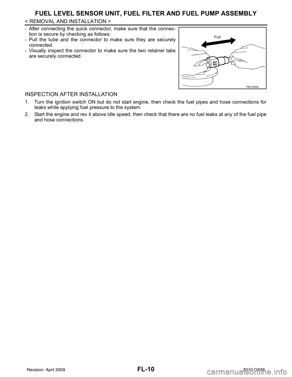
- After connecting the quick connector, make sure that the connec-
tion is secure by checking as follows:
- Pull the tube and the connector to make sure they are securely
connected.
- Visually inspect the connector to make sure the two retainer tabs are securely connected.
INSPECTION AFTER INSTALLATION
1. Turn the ignition switch ON but do not start engi ne, then check the fuel pipes and hose connections for
leaks while applying fuel pressure to the system.
2. Start the engine and rev it above idle speed, then check t hat there are no fuel leaks at any of the fuel pipe
and hose connections.
PBIC1653E
Revision: April 20092010 QX56
Page 2197 of 4210
FUEL TANKFL-15
< REMOVAL AND INSTALLATION >
C
DE
F
G H
I
J
K L
M A
FL
NP
O
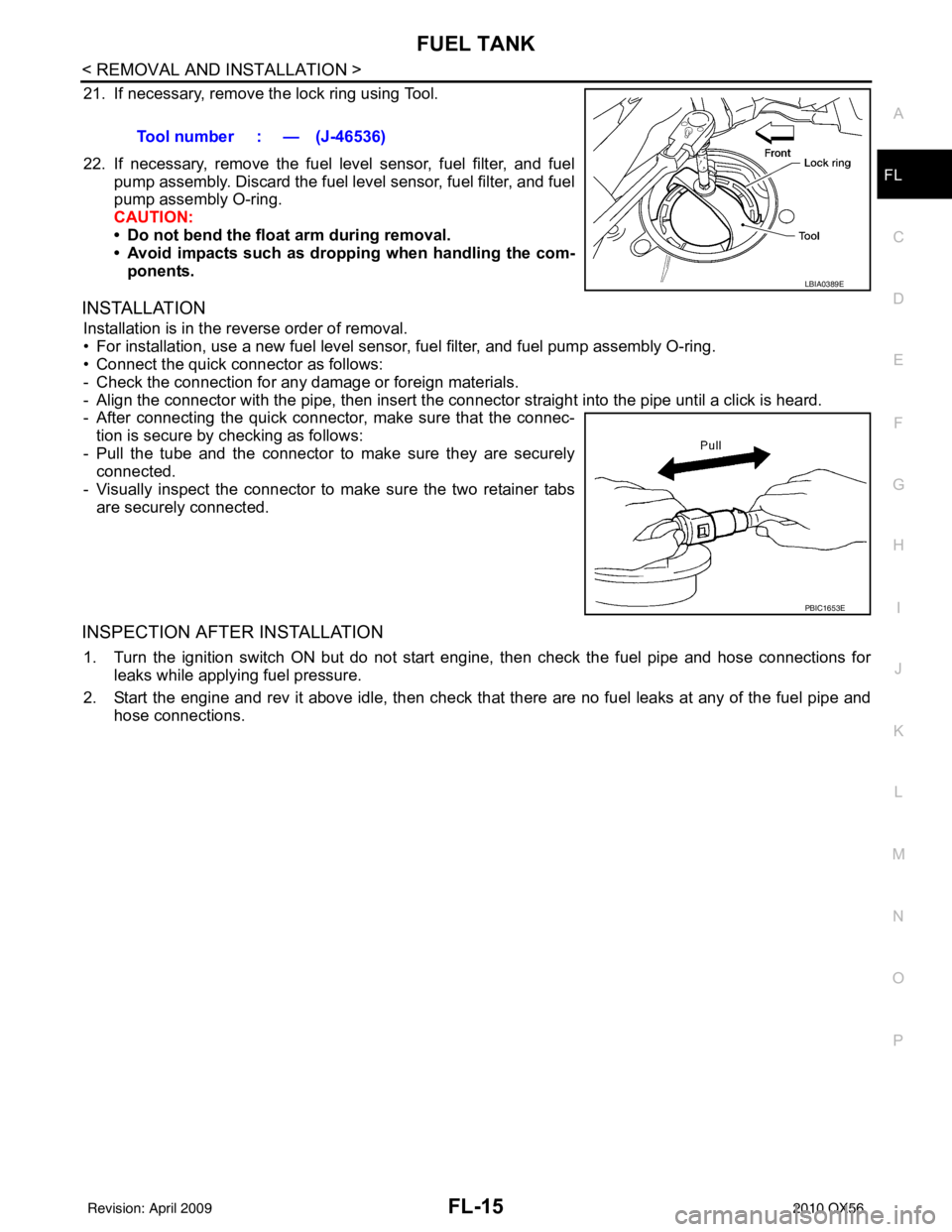
21. If necessary, remove the lock ring using Tool.
22. If necessary, remove the fuel level sensor, fuel filter, and fuel
pump assembly. Discard the fuel level sensor, fuel filter, and fuel
pump assembly O-ring.
CAUTION:
• Do not bend the float arm during removal.
• Avoid impacts such as droppi ng when handling the com-
ponents.
INSTALLATION
Installation is in the reverse order of removal.
• For installation, use a new fuel level sensor, fuel filter, and fuel pump assembly O-ring.
• Connect the quick connector as follows:
- Check the connection for any damage or foreign materials.
- Align the connector with the pipe, t hen insert the connector straight into the pipe until a click is heard.
- After connecting the quick connector, make sure that the connec-
tion is secure by checking as follows:
- Pull the tube and the connector to make sure they are securely connected.
- Visually inspect the connector to make sure the two retainer tabs are securely connected.
INSPECTION AFTER INSTALLATION
1. Turn the ignition switch ON but do not start en gine, then check the fuel pipe and hose connections for
leaks while applying fuel pressure.
2. Start the engine and rev it above idle, then check that there are no fuel leaks at any of the fuel pipe and
hose connections. Tool number : — (J-46536)
LBIA0389E
PBIC1653E
Revision: April 20092010 QX56
Page 2251 of 4210
GI-28
< PRECAUTION >
PRECAUTIONS
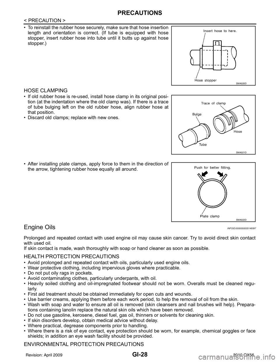
• To reinstall the rubber hose securely, make sure that hose insertionlength and orientation is correct. (If tube is equipped with hose
stopper, insert rubber hose into tube until it butts up against hose
stopper.)
HOSE CLAMPING
• If old rubber hose is re-used, install hose clamp in its original posi-tion (at the indentation where the old clamp was). If there is a trace
of tube bulging left on the old rubber hose, align rubber hose at
that position.
• Discard old clamps; replace with new ones.
• After installing plate clamps, apply force to them in the direction of the arrow, tightening rubber hose equally all around.
Engine OilsINFOID:0000000005149597
Prolonged and repeated contact with used engine oil may cause skin cancer. Try to avoid direct skin contact
with used oil.
If skin contact is made, wash thoroughly with soap or hand cleaner as soon as possible.
HEALTH PROTECTION PRECAUTIONS
• Avoid prolonged and repeated contact with oils, particularly used engine oils.
• Wear protective clothing, including impervious gloves where practicable.
• Do not put oily rags in pockets.
• Avoid contaminating clothes, pa rticularly underpants, with oil.
• Heavily soiled clothing and oil-impregnated footwear should not be worn. Overalls must be cleaned regu- larly.
• First aid treatment should be obtained immediately for open cuts and wounds.
• Use barrier creams, applying them before each work period, to help the removal of oil from the skin.
• Wash with soap and water to ensure all oil is removed (skin cleansers and nail brushes will help). Prepara-
tions containing lanolin replace the natural skin oils which have been removed.
• Do not use gasoline, kerosene, diesel fuel, gas oil, thinners or solvents for cleaning skin.
• If skin disorders develop, obtain medical advice without delay.
• Where practical, degrease components prior to handling.
• Where there is a risk of eye contact, eye protection should be worn, for example, chemical goggles or face
shields; in addition an eye wash facility should be provided.
ENVIRONMENTAL PROTECTION PRECAUTIONS
SMA020D
SMA021D
SMA022D
Revision: April 20092010 QX56
Page 2255 of 4210
GI-32
< PRECAUTION >
TOW TRUCK TOWING
TOW TRUCK TOWING
Tow Truck TowingINFOID:0000000005370267
WARNING:
• Never get under the vehicle while it is supported only by the jack. Always use safety stands to sup-
port the frame when you have to get under the vehicle.
• Place wheel chocks at both front an d back of the wheels on the ground.
CAUTION:
• All applicable State or Provincial (in Canada) laws and local laws regarding the towing operation
must be obeyed.
• It is necessary to use proper towing equipment to avoid possible damage during towing operation.
Towing is in accordance with Towing Procedure Manual at dealer.
• Always attach safety chains before towing.
• When towing, make sure that the transmission, steering system and powertrain are in good order. If any unit is damaged, dollies must be used.
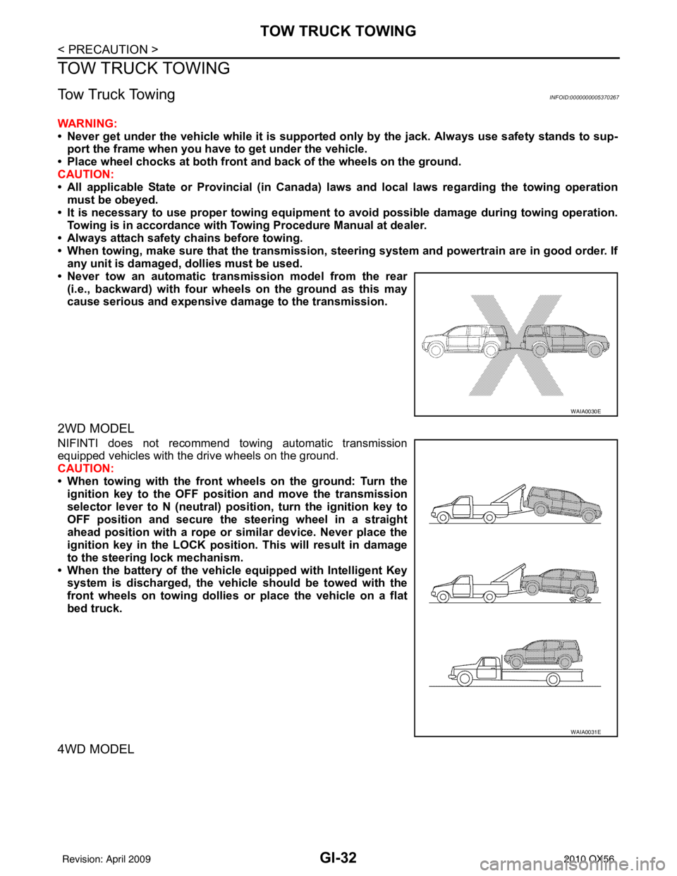
• Never tow an automatic transmission model from the rear (i.e., backward) with four wh eels on the ground as this may
cause serious and expensive dama ge to the transmission.
2WD MODEL
NIFINTI does not recommend towing automatic transmission
equipped vehicles with the drive wheels on the ground.
CAUTION:
• When towing with the front wheels on the ground: Turn the
ignition key to the OFF posit ion and move the transmission
selector lever to N (neutral) pos ition, turn the ignition key to
OFF position and secure the steering wheel in a straight
ahead position with a rope or similar device. Never place the
ignition key in the LOCK position. This will result in damage
to the steering lock mechanism.
• When the battery of the vehicle equipped with Intelligent Key system is discharged, the vehicle should be towed with the
front wheels on towing dollies or place the vehicle on a flat
bed truck.
4WD MODEL
WAIA0030E
WAIA0031E
Revision: April 20092010 QX56
Page 2266 of 4210
SERVICE INFORMATION FOR ELECTRICAL INCIDENTGI-43
< BASIC INSPECTION >
C
DE
F
G H
I
J
K L
M B
GI
N
O P
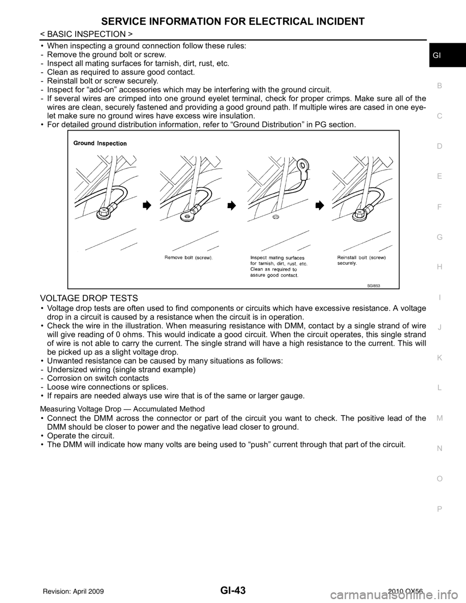
• When inspecting a ground connection follow these rules:
- Remove the ground bolt or screw.
- Inspect all mating surfaces for tarnish, dirt, rust, etc.
- Clean as required to assure good contact.
- Reinstall bolt or screw securely.
- Inspect for “add-on” accessories which may be interfering with the ground circuit.
- If several wires are crimped into one ground eyelet terminal, check for proper crimps. Make sure all of the wires are clean, securely fastened and providing a good ground path. If multiple wires are cased in one eye-
let make sure no ground wires have excess wire insulation.
• For detailed ground distribution information, refer to “Ground Distribution” in PG section.
VOLTAGE DROP TESTS
• Voltage drop tests are often used to find components or circuits which have excessive resistance. A voltage drop in a circuit is caused by a resistance when the circuit is in operation.
• Check the wire in the illustration. When measuring re sistance with DMM, contact by a single strand of wire
will give reading of 0 ohms. This would indicate a good circuit. When the circuit operates, this single strand
of wire is not able to carry the current. The single strand will have a high resistance to the current. This will
be picked up as a slight voltage drop.
• Unwanted resistance can be caused by many situations as follows:
- Undersized wiring (single strand example)
- Corrosion on switch contacts
- Loose wire connections or splices.
• If repairs are needed always use wire that is of the same or larger gauge.
Measuring Voltage Drop — Accumulated Method
• Connect the DMM across the connector or part of the ci rcuit you want to check. The positive lead of the
DMM should be closer to power and the negative lead closer to ground.
• Operate the circuit.
• The DMM will indicate how many volts are being used to “push” current through that part of the circuit.
SGI853
Revision: April 20092010 QX56
Page 2269 of 4210
GI-46
< BASIC INSPECTION >
CONSULT-III CHECKING SYSTEM
CONSULT-III CHECKING SYSTEM
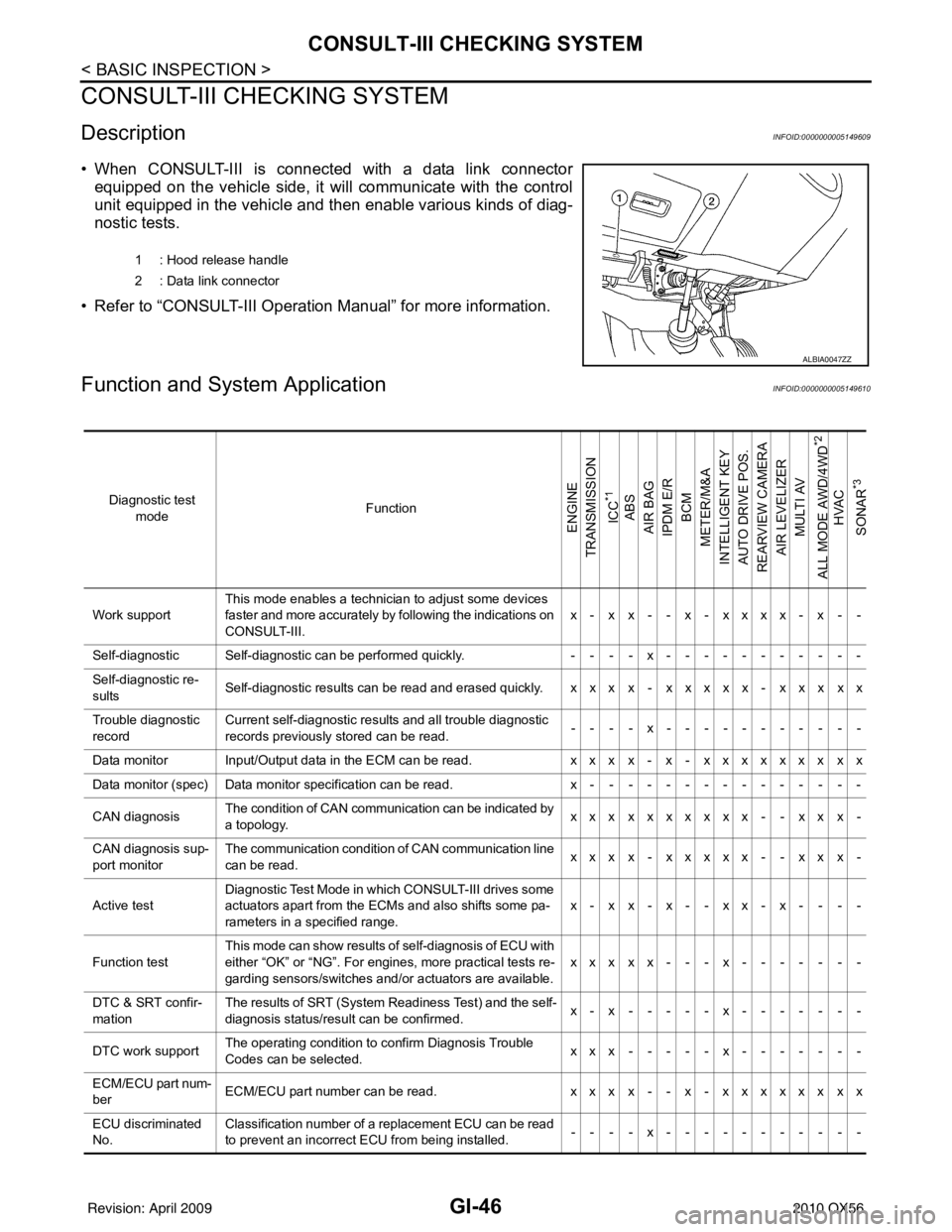
DescriptionINFOID:0000000005149609
• When CONSULT-III is connected with a data link connectorequipped on the vehicle side, it will communicate with the control
unit equipped in the vehicle and then enable various kinds of diag-
nostic tests.
• Refer to “CONSULT-III Operation Manual” for more information.
Function and System ApplicationINFOID:0000000005149610
1 : Hood release handle
2 : Data link connector
ALBIA0047ZZ
Diagnostic test mode Function
ENGINE
TRANSMISSION
ICC
*1
ABS
AIR BAG
IPDM E/R
BCM
METER/M&A
INTELLIGENT KEY
AUTO DRIVE POS.
REARVIEW CAMERA
AIR LEVELIZER MULTI AV
ALL MODE AWD/4WD
*2
HVAC
SONAR
*3
Work support This mode enables a technician to adjust some devices
faster and more accurately by following the indications on
CONSULT-III. x- x x- - x- xxxx- x - -
Self-diagnostic Self-diagnostic can be performed quickly. ----x-----------
Self-diagnostic re-
sults Self-diagnostic results can be read and erased quickly. x x x x - x x x x x - x x x x x
Trouble diagnostic
record Current self-diagnostic results and all trouble diagnostic
records previously stored can be read.
--- - x--- - -------
Data monitor Input/Output data in the ECM can be read. xxx x- x- xxxxxxx xx
Data monitor (spec) Data monitor specification can be read. x---------------
CAN diagnosis The condition of CAN communication can be indicated by
a topology.
xxx xxxxxxx- - xx x-
CAN diagnosis sup-
port monitor The communication condition of CAN communication line
can be read.
xxx x- xxxxx- - xx x-
Active test Diagnostic Test Mode in wh
ich CONSULT-III drives some
actuators apart from the ECMs and also shifts some pa-
rameters in a specified range. x-xx-x--xx-x- - --
Function test This mode can show results of self-diagnosis of ECU with
either “OK” or “NG”. For engines, more practical tests re-
garding sensors/switches and/or actuators are available.
xxxxx---x-------
DTC & SRT confir-
mation The results of SRT (System Readiness Test) and the self-
diagnosis status/result can be confirmed.
x-x-----x-------
DTC work support The operating condition to confirm Diagnosis Trouble
Codes can be selected. xxx-----x-------
ECM/ECU part num-
ber ECM/ECU part number can be read.
xxx x- - x- xxxxxx xx
ECU discriminated
No. Classification number of a replacement ECU can be read
to prevent an incorrect ECU from being installed.
----x-----------
Revision: April 20092010 QX56
Page 2270 of 4210
CONSULT-III CHECKING SYSTEMGI-47
< BASIC INSPECTION >
C
DE
F
G H
I
J
K L
M B
GI
N
O P
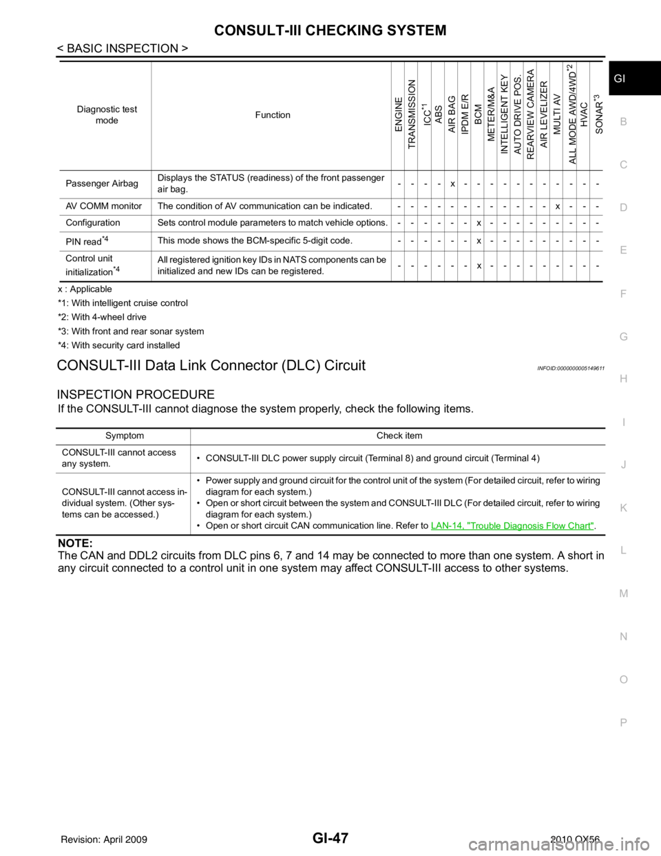
x : Applicable
*1: With intelligent cruise control
*2: With 4-wheel drive
*3: With front and rear sonar system
*4: With security card installed
CONSULT-III Data Link Connector (DLC) CircuitINFOID:0000000005149611
INSPECTION PROCEDURE
If the CONSULT-III cannot diagnose the sys tem properly, check the following items.
NOTE:
The CAN and DDL2 circuits from DLC pins 6, 7 and 14 may be connected to more than one system. A short in
any circuit connected to a control unit in one system may affect CONSULT-III access to other systems.
Passenger AirbagDisplays the STATUS (readiness) of the front passenger
air bag. ----x-----------
AV COMM monitor The condition of AV communication can be indicated. ------------x---
Configuration Sets control module parameters to match vehicle options.------x---------
PIN read
*4This mode shows the BCM-specific 5-digit code. ------x---------
Control unit
initialization
*4All registered ignition key IDs in NATS components can be
initialized and new IDs can be registered. ------x---------
Diagnostic test
mode Function
ENGINE
TRANSMISSION
ICC
*1
ABS
AIR BAG
IPDM E/R BCM
METER/M&A
INTELLIGENT KEY
AUTO DRIVE POS.
REARVIEW CAMERA AIR LEVELIZER MULTI AV
ALL MODE AWD/4WD
*2
HVAC
SONAR
*3
Symptom Check item
CONSULT-III cannot access
any system. • CONSULT-III DLC power supply circuit (Terminal 8) and ground circuit (Terminal 4)
CONSULT-III cannot access in-
dividual system. (Other sys-
tems can be accessed.) • Power supply and ground circuit for the control unit of the system (For detailed circuit, refer to wiring
diagram for each system.)
• Open or short circuit between the system and CONSULT-III DLC (For detailed circuit, refer to wiring
diagram for each system.)
• Open or short circuit CAN communication line. Refer to LAN-14, "
Trouble Diagnosis Flow Chart".
Revision: April 20092010 QX56
Page 2272 of 4210
GW-1
BODY EXTERIOR, DOORS, ROOF & VEHICLE SECURITY
C
DE
F
G H
I
J
L
M
SECTION GW
A
B
GW
N
O P
CONTENTS
GLASS & WINDOW SYSTEM
SYMPTOM DIAGNOSIS ..... ..........................2
SQUEAK AND RATTLE TROUBLE DIAGNO-
SIS .................................................................. .....
2
Work Flow ........................................................... ......2
Generic Squeak and Rattle Troubleshooting ............4
Diagnostic Worksheet ...............................................6
PRECAUTION ...............................................8
PRECAUTIONS .............................................. .....8
Precaution for Supplemental Restraint System
(SRS) "AIR BAG" and "SEAT BELT PRE-TEN-
SIONER" ............................................................. ......
8
Precaution Necessary for Steering Wheel Rota-
tion After Battery Disconnect ............................... ......
8
Handling for Adhesive and Primer ............................9
PREPARATION ...........................................10
PREPARATION .................................................10
Special Service Tool ............................................ ....10
Commercial Service Tool ........................................10
ON-VEHICLE REPAIR .................................11
WINDSHIELD GLASS .......................................11
Removal and Installation ..................................... ....11
REAR WINDOW GLASS AND MOLDING ........13
Removal and Installation .........................................13
FRONT DOOR GLASS AND REGULATOR .....15
Removal and Installation .........................................15
REAR DOOR GLASS AND REGULATOR .......18
Removal and Installation .........................................18
SIDE WINDOW GLASS ....................................21
Removal and Installation .........................................21
Revision: April 20092010 QX56