Page 2107 of 4210
IPDM E/R (INTELLIGENT POWER DISTRIBUTION MODULE ENGINE ROOM)
EXL-131
< ECU DIAGNOSIS >
C
D E
F
G H
I
J
K
M A
B
EXL
N
O P
ABMWA0363GB
Revision: April 20092010 QX56
Page 2108 of 4210
EXL-132
< ECU DIAGNOSIS >
IPDM E/R (INTELLIGENT POWER DISTRIBUTION MODULE ENGINE ROOM)
ABMIA1042GB
Revision: April 20092010 QX56
Page 2109 of 4210
IPDM E/R (INTELLIGENT POWER DISTRIBUTION MODULE ENGINE ROOM)
EXL-133
< ECU DIAGNOSIS >
C
D E
F
G H
I
J
K
M A
B
EXL
N
O P
Fail SafeINFOID:0000000005369901
CAN COMMUNICATION CONTROL
When CAN communication with ECM and BCM is impossible, IPDM E/R performs fail-s afe control. After CAN
communication recovers normally, it also returns to normal control.
If No CAN Communication Is Available With ECM
ABMIA1043GB
Revision: April 20092010 QX56
Page 2110 of 4210

EXL-134
< ECU DIAGNOSIS >
IPDM E/R (INTELLIGENT POWER DISTRIBUTION MODULE ENGINE ROOM)
If No CAN Communication Is Available With BCM
IGNITION RELAY MALFUNCTION DETECTION FUNCTION
• IPDM E/R monitors the voltage at the contact circuit and excitation coil circuit of the ignition relay inside it.
• IPDM E/R judges the ignition relay error if the voltage differs between the contact circuit and the excitation
coil circuit.
• If the ignition relay cannot turn OFF due to contact seizure, it activates the tail lamp relay for 10 minutes to alert the user to the ignition relay malfunction when the ignition switch is turned OFF.
NOTE:
The tail lamp turns OFF when the ignition switch is turned ON.
FRONT WIPER CONTROL
IPDM E/R detects front wiper stop posit ion by a front wiper auto stop signal.
When a front wiper auto stop signal is in the conditions listed below, IPDM E/R stops power supply to wiper
after repeating a front wiper 10 second activation and 20 second stop five times.
NOTE:
This operation status can be confirmed on the IPDM E/R “DATA MONITOR” that displays “Block” for the item
“WIP PROT” while the wiper is stopped.
STARTER MOTOR PROTECTION FUNCTION
IPDM E/R turns OFF the starter control relay to protect the starter motor when the starter control relay remains
active for 90 seconds.
Control part Fail-safe in operation
Cooling fan • Turns ON the cooling fan relay when the ignition switch is turned ON
• Turns OFF the cooling fan relay when the ignition switch is turned OFF
Control part
Fail-safe in operation
Headlamp • Turns ON the headlamp low relay when the ignition switch is turned ON
• Turns OFF the headlamp low relay when the ignition switch is turned OFF
• Headlamp high LH/RH relays OFF
•Parking lamps
• License plate lamps
• Tail lamps • Turns ON the tail lamp relay when the ignition switch is turned ON
• Turns OFF the tail lamp relay when the ignition switch is turned OFF
Front wiper • The status just before activation of fail-safe control is maintained until the ignition
switch is turned OFF while the front wiper is operating at LO or HI speed.
• The wiper is operated at LO speed until the ignition switch is turned OFF if the fail- safe control is activated while the front wipe r is set in the INT mode and the front wiper
motor is operating.
Rear window defogger Rear window defogger relay OFF
A/C compressor A/C relay OFF
Front fog lamps Front fog lamp relay OFF
Ignition switch Ignition relayTail lamp relay
ON ON —
OFF OFF —
Ignition switchFront wiper switch Auto stop signal
ON OFF
Front wiper stop position signal cannot be
input 10 seconds.
ON The signal does not change for 10 seconds.
Revision: April 20092010 QX56
Page 2111 of 4210
IPDM E/R (INTELLIGENT POWER DISTRIBUTION MODULE ENGINE ROOM)
EXL-135
< ECU DIAGNOSIS >
C
D E
F
G H
I
J
K
M A
B
EXL
N
O P
DTC IndexINFOID:0000000005369902
NOTE:
The details of TIME display are as follows.
• CRNT: The malfunctions that are detected now
• 1 - 39: The number is indicated when it is normal at present and a malfunction was detected in the past. It
increases like 0 → 1 → 2 ··· 38 → 39 after returning to the normal condition whenever IGN OFF → ON. It is
fixed to 39 until the self-diagnosis results are erased if it is over 39. It returns to 0 when a malfunction is
detected again in the process.
CONSULT-III display Fail-safe
TIMENOTERefer to
No DTC is detected.
further testing
may be required. ————
U1000: CAN COMM CIRCUIT ×CRNT 1 – 39 PCS-17
Revision: April 20092010 QX56
Page 2124 of 4210

EXL-148
< REMOVAL AND INSTALLATION >
HEADLAMP
REMOVAL AND INSTALLATION
HEADLAMP
Bulb ReplacementINFOID:0000000005146698
CAUTION:
• Disconnect battery negative terminal before touching xenon bulb or headlamp wiring harness
assembly.
• Turn headlamp switch OFF before disconnecting headlamp harness connector.
• Do not touch bulb by hand right after being turned off. Burning may result.
• Do not touch the glass of bulb directly by hand. Keep grease and other oily substances away from it.
• Do not turn xenon bulb ON wh en xenon bulb is removed from front combination lamp assembly.
• After installing the bulb, be sure to install the bulb socket securely to ensure watertightness.
• Do not leave bulb out of front combination lamp assembly for a long time because dust, moisture,
smoke, etc. may affect the performa nce of the lamp. When replacing bulb, be sure to replace it with a
new one.
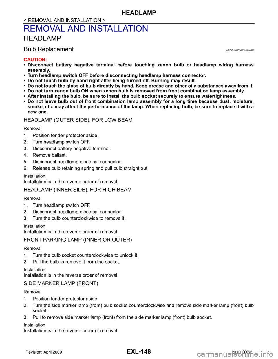
HEADLAMP (OUTER SIDE), FOR LOW BEAM
Removal
1. Position fender protector aside.
2. Turn headlamp switch OFF.
3. Disconnect battery negative terminal.
4. Remove ballast.
5. Disconnect headlamp electrical connector.
6. Release bulb retaining spring and pull bulb straight out.
Installation
Installation is in the reverse order of removal.
HEADLAMP (INNER SIDE), FOR HIGH BEAM
Removal
1. Turn headlamp switch OFF.
2. Disconnect headlamp electrical connector.
3. Turn the bulb counterclockwise to remove it.
Installation
Installation is in the reverse order of removal.
FRONT PARKING LAMP (INNER OR OUTER)
Removal
1. Turn the bulb socket counterclockwise to unlock it.
2. Pull the bulb to remove it from the socket.
Installation
Installation is in the reverse order of removal.
SIDE MARKER LAMP (FRONT)
Removal
1. Position fender protector aside.
2. Turn the side marker lamp (front) bulb socket counterclockwise and remove side marker lamp (front) bulb socket.
3. Pull to remove side marker lamp (front) fr om the side marker lamp (front) bulb socket.
Installation
Installation is in the reverse order of removal.
Revision: April 20092010 QX56
Page 2125 of 4210

HEADLAMPEXL-149
< REMOVAL AND INSTALLATION >
C
DE
F
G H
I
J
K
M A
B
EXL
N
O P
Removal and InstallationINFOID:0000000005146699
FRONT COMBINATION LAMP ASSEMBLY
CAUTION:
• Disconnect battery negative terminal before touc hing xenon bulb or headlamp wiring harness
assembly.
• Turn headlamp switch OFF before di sconnecting headlamp harness connector.
• Do not touch bulb by hand right after being turned off. Burning may result.
• Do not touch the glass of bulb directly by hand. Keep grease and other oily substances away from it.
• Do not turn xenon bulb ON when xenon bulb is removed fr om front combination lamp assembly.
• After installing the bu lb, be sure to install the bulb socket securely to ensure watertightness.
• Do not leave bulb out of front combination lamp assembly for a lo ng time because dust, moisture,
smoke, etc. may affect the performance of the lamp. When replacing bulb, be sure to replace it with a
new one.
Removal
1. Disconnect battery negative terminal.
2. Disconnect front combination lamp assembly.
3. Remove front fascia. Refer to EXT-13, "
Removal and Installation".
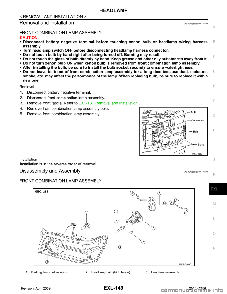
4. Remove front combination lamp assembly bolts.
5. Remove front combination lamp assembly.
Installation
Installation is in the reverse order of removal.
Disassembly and AssemblyINFOID:0000000005146700
FRONT COMBINATION LAMP ASSEMBLY
WKIA1860E
1. Parking lamp bulb (outer) 2. Headlamp bulb (high beam) 3. Headlamp assembly
ALKIA1536GB
Revision: April 20092010 QX56
Page 2136 of 4210

EXT-1
BODY EXTERIOR, DOORS, ROOF & VEHICLE SECURITY
C
DE
F
G H
I
J
L
M
SECTION EXT
A
B
EXT
N
O P
CONTENTS
EXTERIOR
SERVICE INFORMATION .. ..........................2
PRECAUTIONS .............................................. .....2
Precaution for Supplemental Restraint System
(SRS) "AIR BAG" and "SEAT BELT PRE-TEN-
SIONER" ............................................................. ......
2
Precaution Necessary for Steering Wheel Rota-
tion After Battery Disconnect ............................... ......
2
Service Notice ...........................................................3
PREPARATION ...................................................4
Special Service Tool ........................................... ......4
Commercial Service Tool ..........................................4
SQUEAK AND RATTLE TROUBLE DIAG-
NOSES ................................................................
5
Work Flow ........................................................... ......5
Generic Squeak and Rattle Troubleshooting ............7
Diagnostic Worksheet ...............................................9
CLIP AND FASTENER .......................................11
Description .......................................................... ....11
FRONT BUMPER ...............................................13
Removal and Installation .........................................13
REAR BUMPER ............................................. ....15
Removal and Installation .........................................15
FRONT GRILLE .................................................17
Removal and Installation ..................................... ....17
COWL TOP .......................................................18
Removal and Installation .........................................18
FRONT FENDER ...............................................20
Removal and Installation .........................................20
OVER FENDER .................................................21
Removal and Installation .........................................21
FENDER PROTECTOR ....................................23
Removal and Installation .........................................23
LICENSE LAMP FINISHER ..............................24
Removal and Installation .........................................24
RUNNING BOARDS .........................................25
Removal and Installation .........................................25
REAR SPOILER ................................................26
Removal and Installation .........................................26
ROOF RACK .....................................................27
Removal and Installation ..................................... ....27
DOOR OUTSIDE MOLDING .............................28
Removal and Installation .........................................28
SIDE GUARD MOLDING ..................................30
Removal and Installation ..................................... ....30
Revision: April 20092010 QX56