2010 INFINITI QX56 wiring diagram
[x] Cancel search: wiring diagramPage 3617 of 4210
DIAGNOSIS SENSOR UNITSRC-71
< ECU DIAGNOSIS >
C
DE
F
G
I
J
K L
M A
B
SRC
N
O P
ECU DIAGNOSIS
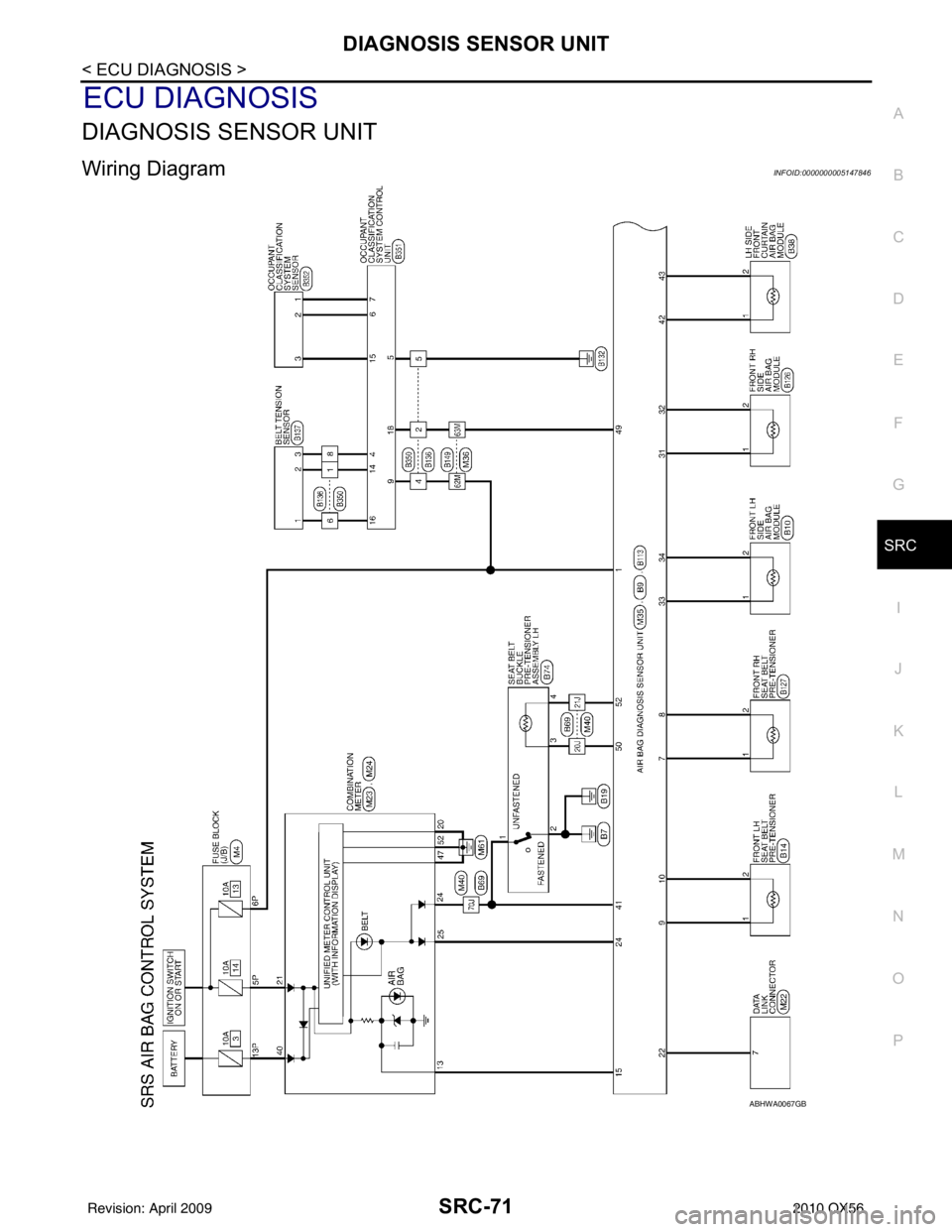
DIAGNOSIS SENSOR UNIT
Wiring DiagramINFOID:0000000005147846
ABHWA0067GB
Revision: April 20092010 QX56
Page 3639 of 4210

ST-1
STEERING
C
DE
F
H I
J
K L
M
SECTION ST
A
B
ST
N
O P
CONTENTS
STEERING SYSTEM
PRECAUTION ....... ........................................3
PRECAUTIONS .............................................. .....3
Precaution for Supplemental Restraint System
(SRS) "AIR BAG" and "SEAT BELT PRE-TEN-
SIONER" ............................................................. ......
3
Precaution Necessary for Steering Wheel Rota-
tion After Battery Disconnect ............................... ......
3
PREPARATION ............................................5
PREPARATION .............................................. .....5
Special Service Tool ........................................... ......5
Commercial Service Tool ..........................................6
FUNCTION DIAGNOSIS ...............................7
HEATED STEERING WHEEL ........................ .....7
System Diagram .................................................. ......7
System Description ...................................................7
Component Parts Location ........................................7
Component Description .............................................8
COMPONENT DIAGNOSIS ..........................9
HEATED STEERING WHEEL ........................ .....9
Wiring Diagram ................................................... ......9
SYMPTOM DIAGNOSIS ..............................12
NOISE, VIBRATION AND HARSHNESS
(NVH) TROUBLESHOOTING ........................ ....
12
NVH Troubleshooting Chart ................................ ....12
ON-VEHICLE MAINTENANCE ....................13
POWER STEERING FLUID ........................... ....13
Checking Fluid Level ........................................... ....13
Checking Fluid Leakage ..........................................13
Air Bleeding Hydraulic System ................................13
ON-VEHICLE REPAIR .................................15
STEERING WHEEL ..........................................15
On-Vehicle Inspection and Service ..................... ....15
POWER STEERING OIL PUMP .......................17
On-Vehicle Inspection and Service .........................17
REMOVAL AND INSTALLATION ...............18
STEERING WHEEL ..........................................18
Removal and Installation ..................................... ....18
TILT SYSTEM ...................................................19
Removal and Installation .........................................19
STEERING COLUMN ........................................20
Removal and Installation .........................................20
POWER STEERING GEAR AND LINKAGE ....23
Removal and Installation .........................................23
POWER STEERING OIL PUMP .......................26
Removal and Installation .........................................26
HYDRAULIC LINE ............................................27
Removal and Installation .........................................27
DISASSEMBLY AND ASSEMBLY ..............29
STEERING COLUMN ........................................29
Disassembly and Assembly ................................. ....29
POWER STEERING GEAR AND LINKAGE ....31
Disassembly and Assembly .....................................31
POWER STEERING OIL PUMP .......................34
Disassembly and Assembly .....................................34
SERVICE DATA AND SPECIFICATIONS
(SDS) ............... .......................................... ...
35
SERVICE DATA AND SPECIFICATIONS
(SDS) .................................................................
35
Steering Wheel .................................................... ....35
Revision: April 20092010 QX56
Page 3647 of 4210
HEATED STEERING WHEELST-9
< COMPONENT DIAGNOSIS >
C
DE
F
H I
J
K L
M A
B
ST
N
O P
COMPONENT DIAGNOSIS
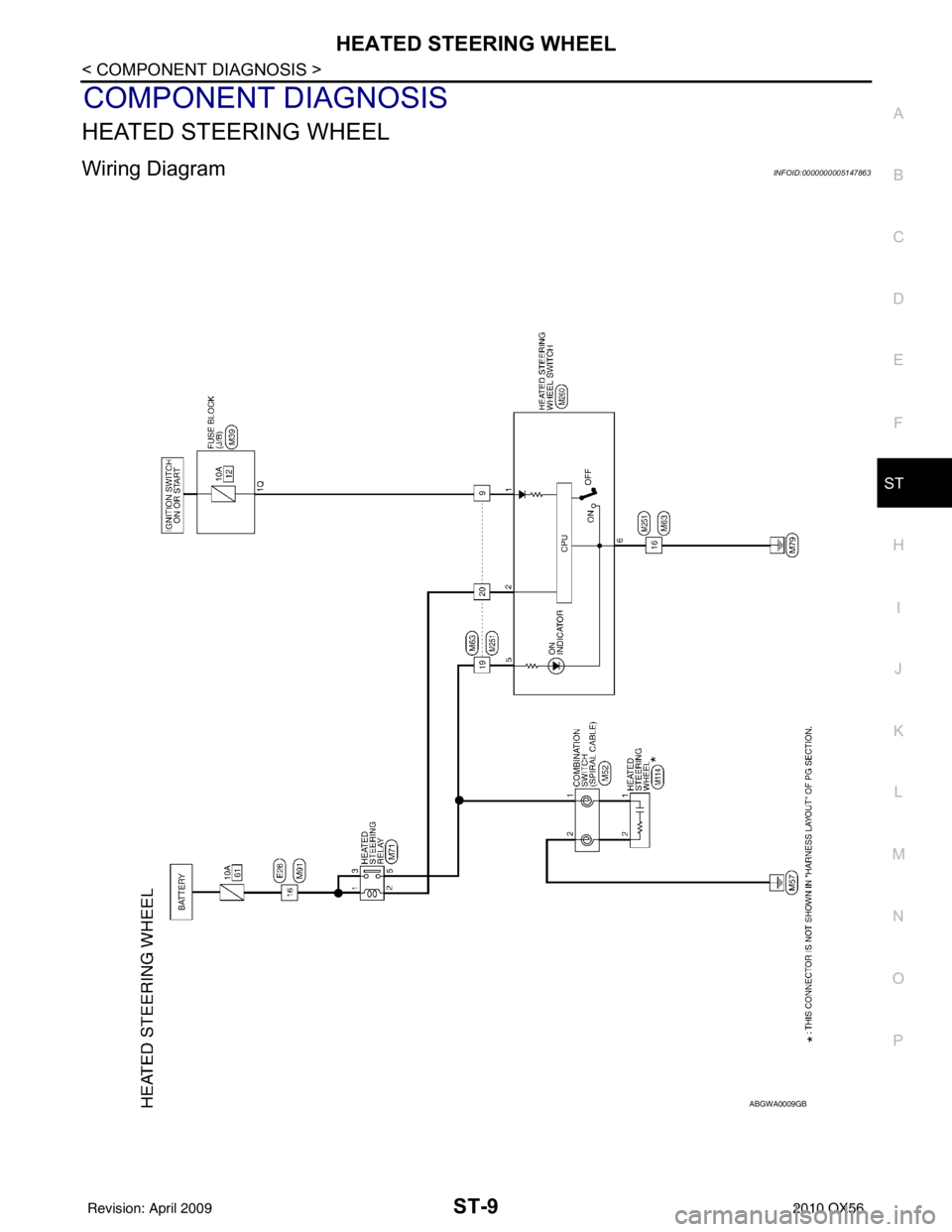
HEATED STEERING WHEEL
Wiring DiagramINFOID:0000000005147863
ABGWA0009GB
Revision: April 20092010 QX56
Page 3676 of 4210

STR-1
ENGINE
C
DE
F
G H
I
J
K L
M
SECTION STR
A
STR
N
O P
CONTENTS
STARTING SYSTEM
PRECAUTION ....... ........................................2
PRECAUTIONS .............................................. .....2
Precaution for Supplemental Restraint System
(SRS) "AIR BAG" and "SEAT BELT PRE-TEN-
SIONER" ............................................................. ......
2
Precaution Necessary for Steering Wheel Rota-
tion After Battery Disconnect ............................... ......
2
Precaution for Power Generation Variable Voltage
Control System ..........................................................
3
PREPARATION ............................................4
PREPARATION .............................................. .....4
Special Service Tool ........................................... ......4
Commercial Service Tool ..........................................4
BASIC INSPECTION ....................................5
DIAGNOSIS AND REPAIR WORKFLOW ..... .....5
Work Flow ........................................................... ......5
FUNCTION DIAGNOSIS ...............................8
STARTING SYSTEM ...................................... .....8
System Diagram .................................................. ......8
System Description ...................................................8
Component Parts Location ........................................8
Component Description ............................................9
COMPONENT DIAGNOSIS .........................10
B TERMINAL CIRCUIT .....................................10
Description ........................................................... ....10
Diagnosis Procedure ...............................................10
S CONNECTOR CIRCUIT .................................12
Description ...............................................................12
Diagnosis Procedure ...............................................12
STARTING SYSTEM .........................................14
Wiring Diagram .................................................... ....14
SYMPTOM DIAGNOSIS ..............................18
STARTING SYSTEM .........................................18
Symptom Table ................................................... ....18
ON-VEHICLE REPAIR .................................19
STARTER MOTOR ...........................................19
Removal and Installation ..................................... ....19
SERVICE DATA AND SPECIFICATIONS
(SDS) ............... .......................................... ...
20
STARTER MOTOR ...........................................20
Starter .................................................................. ....20
Revision: April 20092010 QX56
Page 3685 of 4210
STR-10
< COMPONENT DIAGNOSIS >
B TERMINAL CIRCUIT
COMPONENT DIAGNOSIS
B TERMINAL CIRCUIT
DescriptionINFOID:0000000005149554
Terminal "2" (B) is constantly supplied with battery power.
Diagnosis ProcedureINFOID:0000000005149555
Regarding Wiring Diagram information, refer to STR-14, "Wiring Diagram".
CAUTION:
Perform diagnosis under the condi tion that the engine cannot start by the following procedure.
1. Remove fuel pump fuse.
2. Crank or start the engine (where possible) until the fuel pressure is depleted.
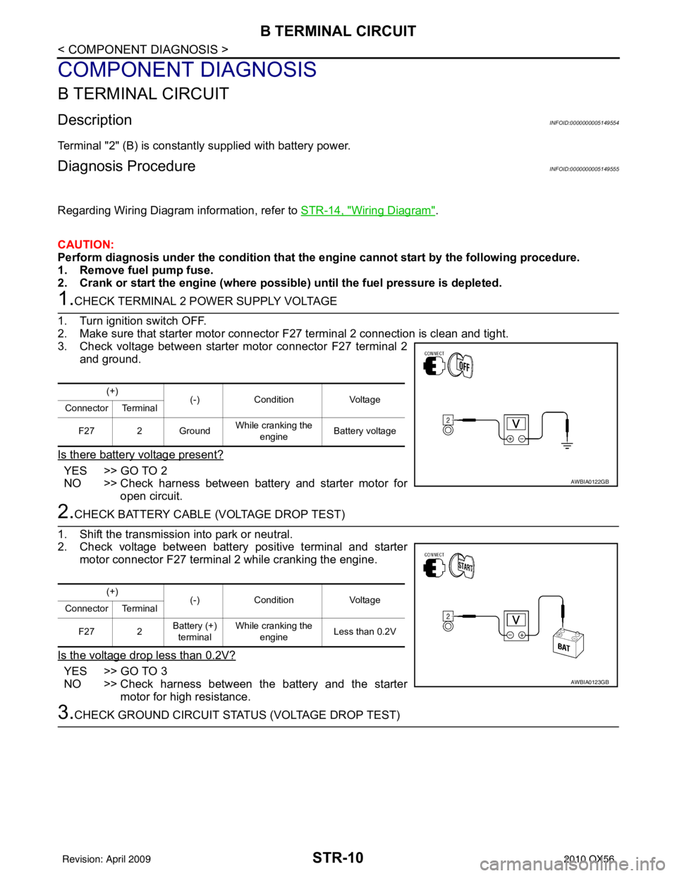
1.CHECK TERMINAL 2 POWER SUPPLY VOLTAGE
1. Turn ignition switch OFF.
2. Make sure that starter motor connector F27 terminal 2 connection is clean and tight.
3. Check voltage between starter motor connector F27 terminal 2
and ground.
Is there battery voltage present?
YES >> GO TO 2
NO >> Check harness between battery and starter motor for open circuit.
2.CHECK BATTERY CABLE (VOLTAGE DROP TEST)
1. Shift the transmission into park or neutral.
2. Check voltage between battery positive terminal and starter motor connector F27 terminal 2 while cranking the engine.
Is the voltage drop less than 0.2V?
YES >> GO TO 3
NO >> Check harness between the battery and the starter motor for high resistance.
3.CHECK GROUND CIRCUIT STATUS (VOLTAGE DROP TEST)
(+) (-)Condition Voltage
Connector Terminal
F27 2 Ground While cranking the
engine Battery voltage
AWBIA0122GB
(+)
(-)Condition Voltage
Connector Terminal
F27 2 Battery (+)
terminal While cranking the
engine Less than 0.2V
AWBIA0123GB
Revision: April 20092010 QX56
Page 3687 of 4210
STR-12
< COMPONENT DIAGNOSIS >
S CONNECTOR CIRCUIT
S CONNECTOR CIRCUIT
DescriptionINFOID:0000000005149556
Terminal "1" (S) is the power supply for the starter motor magnetic switch. Terminal 1 is supplied with power
when the ignition switch is turned to the START position while the selector lever is in the P or N position.
Diagnosis ProcedureINFOID:0000000005149557
Regarding Wiring Diagram information, refer to STR-14, "Wiring Diagram".
CAUTION:
Perform diagnosis under the condi tion that engine cannot start by the following procedure.
1. Remove fuel pump fuse.
2. Crank or start the engine (where possi ble) until the fuel pressure is released.
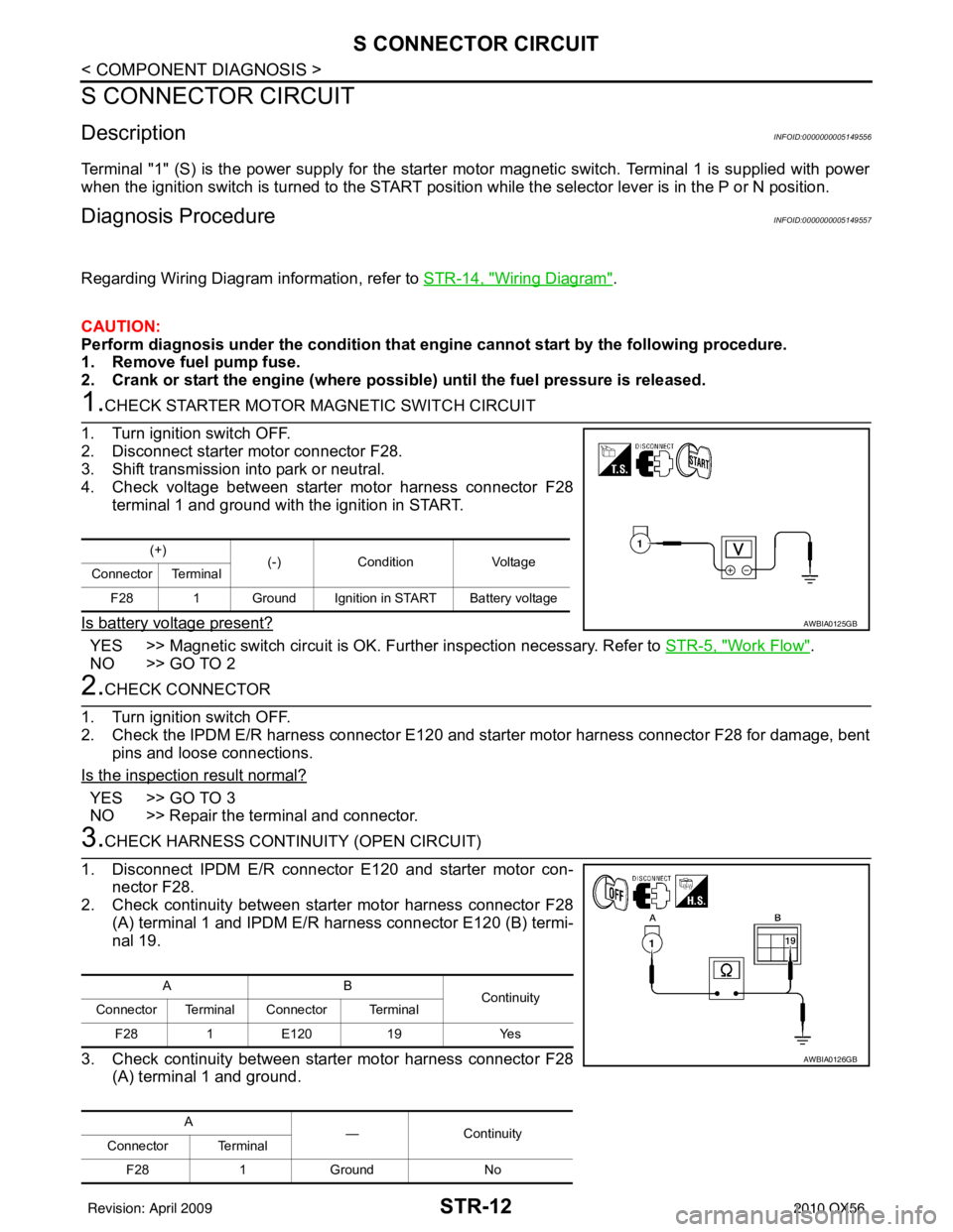
1.CHECK STARTER MOTOR MAGNETIC SWITCH CIRCUIT
1. Turn ignition switch OFF.
2. Disconnect starter motor connector F28.
3. Shift transmission into park or neutral.
4. Check voltage between starter motor harness connector F28 terminal 1 and ground with the ignition in START.
Is battery voltage present?
YES >> Magnetic switch circuit is OK. Further inspection necessary. Refer to STR-5, "Work Flow".
NO >> GO TO 2
2.CHECK CONNECTOR
1. Turn ignition switch OFF.
2. Check the IPDM E/R harness connector E120 and st arter motor harness connector F28 for damage, bent
pins and loose connections.
Is the inspection result normal?
YES >> GO TO 3
NO >> Repair the terminal and connector.
3.CHECK HARNESS CONTI NUITY (OPEN CIRCUIT)
1. Disconnect IPDM E/R connector E120 and starter motor con- nector F28.
2. Check continuity between starter motor harness connector F28
(A) terminal 1 and IPDM E/R harness connector E120 (B) termi-
nal 19.
3. Check continuity between starter motor harness connector F28 (A) terminal 1 and ground.
(+) (-)Condition Voltage
Connector Terminal
F28 1 Ground Ignition in START Battery voltage
AWBIA0125GB
AB Continuity
Connector Terminal Connector Terminal
F28 1E120 19 Yes
A —Contin u it y
Connector Terminal
F28 1Ground No
AWBIA0126GB
Revision: April 20092010 QX56
Page 3689 of 4210
STR-14
< COMPONENT DIAGNOSIS >
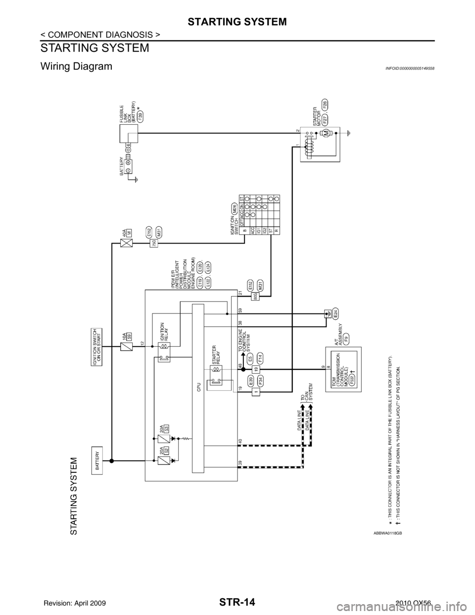
STARTING SYSTEM
STARTING SYSTEM
Wiring DiagramINFOID:0000000005149558
ABBWA0118GB
Revision: April 20092010 QX56
Page 3698 of 4210

TM-3
CEF
G H
I
J
K L
M A
B
TM
N
O P
Diagnosis Procedure ...........................................
....
80
P1752 INPUT CLUTCH SOLENOID ..................82
Description .......................................................... ....82
CONSULT-III Reference Value in Data Monitor
Mode ................................................................... ....
82
On Board Diagnosis Logic ......................................82
Possible Cause .......................................................82
DTC Confirmation Procedure ..................................82
Diagnosis Procedure ...............................................82
P1757 FRONT BRAKE SOLENOID ...................84
Description .......................................................... ....84
CONSULT-III Reference Value in Data Monitor
Mode ................................................................... ....
84
On Board Diagnosis Logic ......................................84
Possible Cause .......................................................84
DTC Confirmation Procedure ..................................84
Diagnosis Procedure ...............................................84
P1762 DIRECT CLUTCH SOLENOID ................86
Description .......................................................... ....86
CONSULT-III Reference Value in Data Monitor
Mode ................................................................... ....
86
On Board Diagnosis Logic ......................................86
Possible Cause .......................................................86
DTC Confirmation Procedure ..................................86
Diagnosis Procedure ...............................................86
P1767 HIGH AND LOW REVERSE CLUTCH
SOLENOID .........................................................
88
Description .......................................................... ....88
CONSULT-III Reference Value in Data Monitor
Mode ................................................................... ....
88
On Board Diagnosis Logic ......................................88
Possible Cause .......................................................88
DTC Confirmation Procedure ..................................88
Diagnosis Procedure ...............................................88
P1772 LOW COAST BRAKE SOLENOID .........90
Description .......................................................... ....90
CONSULT-III Reference Value in Data Monitor
Mode ................................................................... ....
90
On Board Diagnosis Logic ......................................90
Possible Cause .......................................................90
DTC Confirmation Procedure ..................................90
Diagnosis Procedure ...............................................90
P1774 LOW COAST BRAKE SOLENOID .........92
Description .......................................................... ....92
CONSULT-III Reference Value in Data Monitor
Mode ................................................................... ....
92
On Board Diagnosis Logic ......................................92
Possible Cause .......................................................92
DTC Confirmation Procedure ..................................92
Diagnosis Procedure ...............................................93
MAIN POWER SUPPLY AND GROUND CIR-
CUIT ....................................................................
94
Diagnosis Procedure ........................................... ....94
CLOSED THROTTLE POSITION AND WIDE
OPEN THROTTLE POSITION CIRCUIT ...........
96
CONSULT-III Reference Value in Data Monitor
Mode .................................................................... ....
96
Diagnosis Procedure ...............................................96
BRAKE SIGNAL CIRCUIT ................................97
CONSULT-III Reference Va lue in Data Monitor
Mode .................................................................... ....
97
Diagnosis Procedure ...............................................97
TOW MODE SWITCH .......................................98
Description ...............................................................98
Diagnosis Procedure ...............................................98
A/T SHIFT LOCK SYSTEM ...............................99
Description ...............................................................99
Terminals And Reference Values ............................99
Wiring Diagram - A/T SH IFT LOCK SYSTEM - .....100
Component Inspection ......................................... ..103
ECU DIAGNOSIS .......................................106
TCM .................................................................106
Reference Value .................................................. ..106
Wiring Diagram — A/T CONTROL SYSTEM — .. ..108
Fail-Safe .............................................................. ..117
DTC Inspection Priority Chart ................................119
DTC No. Index .......................................................119
DTC Alphabetical Index .........................................120
SYMPTOM DIAGNOSIS ............................121
SYSTEM SYMPTOM .......................................121
Symptom Table ................................................... ..121
PRECAUTION ............................................143
PRECAUTIONS ...............................................143
Precaution for Supplemental Restraint System
(SRS) "AIR BAG" and "SEAT BELT PRE-TEN-
SIONER" ............................................................. ..
143
Precaution for On Board Diagnosis (OBD) System
of A/T and Engine ................................................ ..
143
Precaution .............................................................143
Service Notice or Precaution .................................144
PREPARATION .........................................146
PREPARATION ...............................................146
Special Service Tool ............................................ ..146
Commercial Service Tool ......................................147
ON-VEHICLE MAINTENANCE ..................148
A/T FLUID .......................................................148
Checking the A/T Fluid (ATF) .............................. ..148
Changing the A/T Fluid (ATF) ................................150
A/T FLUID COOLER .......................................152
A/T Fluid Cooler Cleaning .....................................152
Inspection ..............................................................154
Revision: April 20092010 QX56