2010 INFINITI QX56 wiring diagram
[x] Cancel search: wiring diagramPage 3716 of 4210
A/T CONTROL SYSTEMTM-21
< FUNCTION DIAGNOSIS >
CEF
G H
I
J
K L
M A
B
TM
N
O P
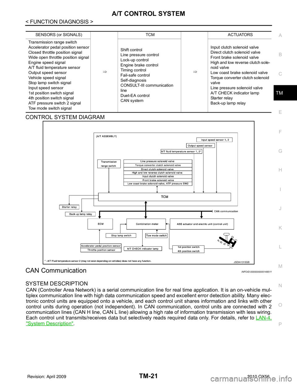
CONTROL SYSTEM DIAGRAM
CAN CommunicationINFOID:0000000005148511
SYSTEM DESCRIPTION
CAN (Controller Area Network) is a serial communication line for real time application. It is an on-vehicle mul-
tiplex communication line with high data communication speed and excellent error detection ability. Many elec-
tronic control units are equipped onto a vehicle, and each control unit shares information and links with other
control units during operation (not independent). In CAN communication, control units are connected with 2
communication lines (CAN H line, CAN L line) allowing a high rate of information transmission with less wiring.
Each control unit transmits/receives data but selectively reads required data only. For details, refer to LAN-4,
"System Description".
SENSORS (or SIGNALS)
⇒TCM
⇒ACTUATORS
Transmission range switch
Accelerator pedal position sensor
Closed throttle position signal
Wide open throttle position signal
Engine speed signal
A/T fluid temperature sensor
Output speed sensor
Vehicle speed signal
Stop lamp switch signal
Input speed sensor
1st position switch signal
4th position switch signal
ATF pressure switch 2 signal
Tow mode switch signal Shift control
Line pressure control
Lock-up control
Engine brake control
Timing control
Fail-safe control
Self-diagnosis
CONSULT-III co
mmunication
line
Duet-EA control
CAN system Input clutch solenoid valve
Direct clutch solenoid valve
Front brake solenoid valve
High and low reverse clutch sole-
noid valve
Low coast brake solenoid valve
Torque converter clutch solenoid
valve
Line pressure solenoid valve
A/T CHECK indicator lamp
Starter relay
Back-up lamp relay
JSDIA1315GB
Revision: April 20092010 QX56
Page 3795 of 4210
TM-100
< COMPONENT DIAGNOSIS >
A/T SHIFT LOCK SYSTEM
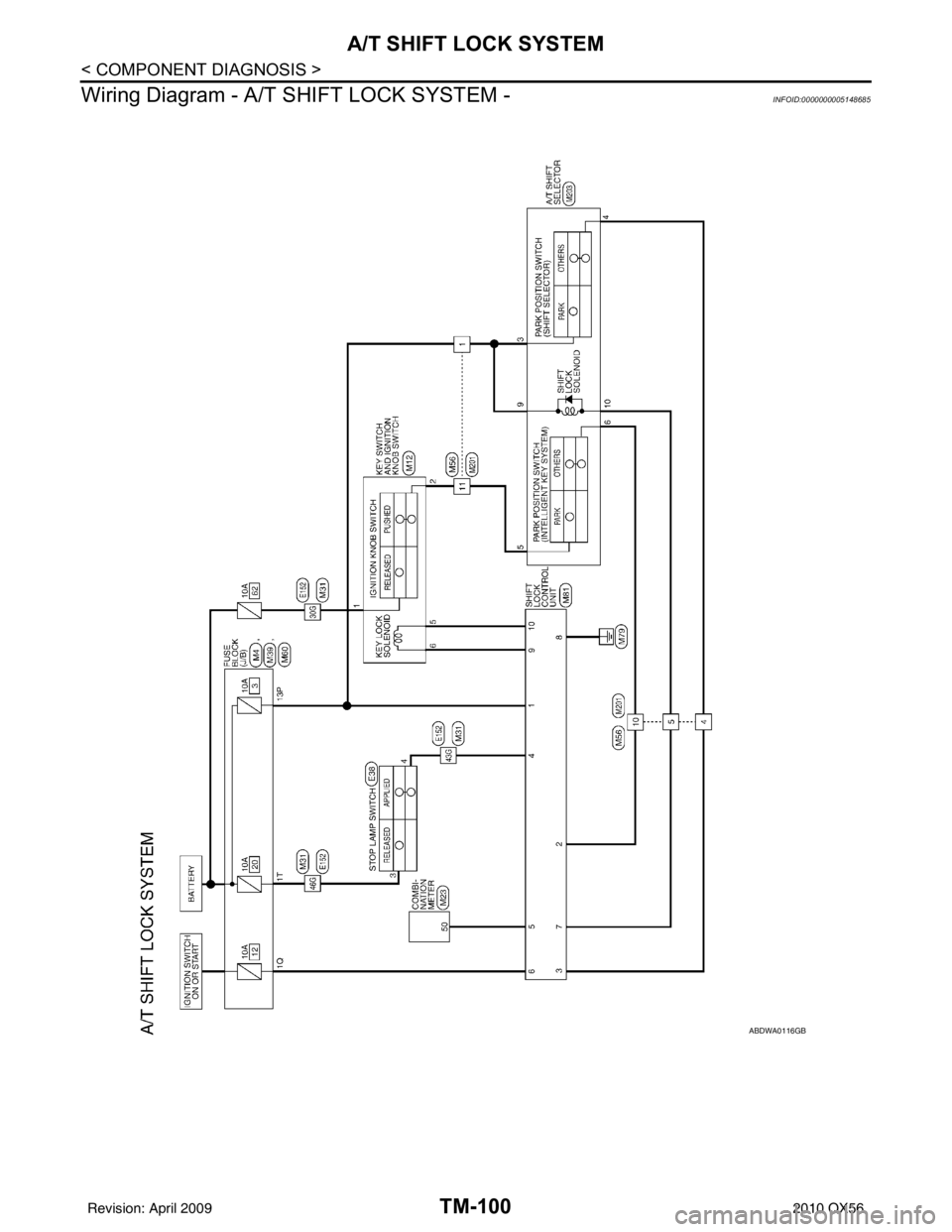
Wiring Diagram - A/T SHIFT LOCK SYSTEM -
INFOID:0000000005148685
ABDWA0116GB
Revision: April 20092010 QX56
Page 3803 of 4210
TM-108
< ECU DIAGNOSIS >
TCM
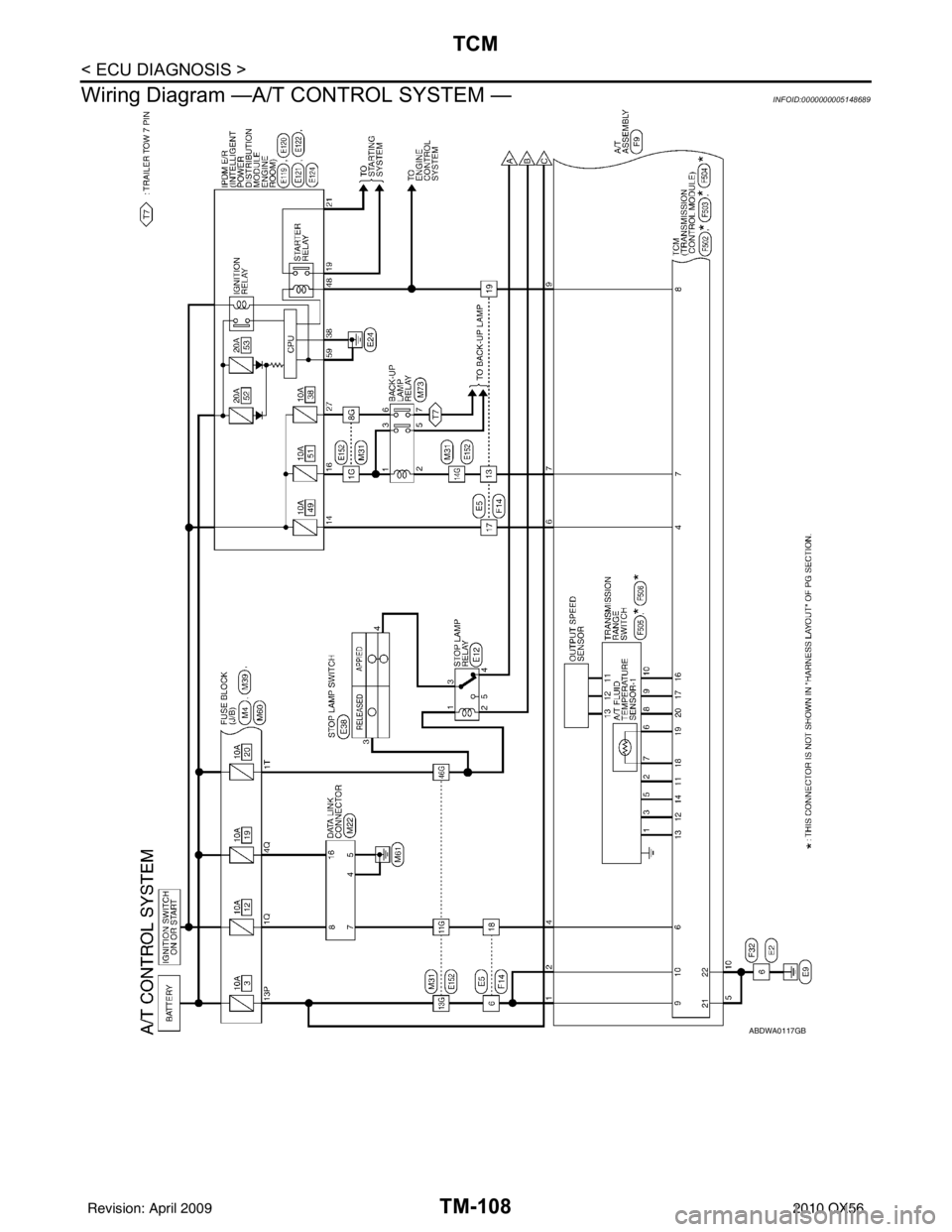
Wiring Diagram —A/T CONTROL SYSTEM —
INFOID:0000000005148689
ABDWA0117GB
Revision: April 20092010 QX56
Page 3980 of 4210
VTL-18
< ON-VEHICLE REPAIR >
HEATER & COOLING UNIT ASSEMBLY
1. Move the two front seats to the rear most position on the seat track.
2. Disconnect the battery negative terminal and battery positive terminal.
3. Discharge the refrigerant from the A/C system. Refer to HA-20, "
HFC-134a (R-134a) Service Procedure".
4. Drain the coolant from the engine cooling system. Refer to CO-11, "
Changing Engine Coolant".
5. Disconnect the front heater hoses from the front heater core.
6. Disconnect the high/low pressure pipes from the front expansion valve.
7. Remove the instrument panel and console panel. Refer to IP-12, "
Removal and Installation".
8. Disconnect the instrument panel wire harness at the RH and LH in-line connector brackets, and the fuse block (J/B) electrical connectors. Refer to PG-9, "
Wiring Diagram — Battery Power Supply —".
9. Disconnect the steering member from each side of the vehicle body.
10. Remove the front heater and cooling unit assembly with it attached to the steering member, from the vehi-
cle.
CAUTION:
Use care not to damage the seats and interior tr im panels when removing the front heater and
cooling unit assembly with it at tached to the steering member.
11. Remove the front heater and cooling unit assembly from the steering member.
Installation
Installation is in the reverse order of removal.
CAUTION:
• Replace the O-ring of the low-pressure pipe and high-pressure pipe with a new one, and apply com-
pressor oil to it when installing it.
• After charging the refrigerant, check for leaks.
NOTE:
• Fill the engine cooling system with the specified coolant mixture. Refer to CO-11, "
Changing Engine Cool-
ant".
• Recharge the A/C system. Refer to HA-20, "
HFC-134a (R-134a) Service Procedure".
REAR HEATER AND COOLING UNIT ASSEMBLY
Removal
1. Discharge the refrigerant from the A/C system. Refer to HA-20, "HFC-134a (R-134a) Service Procedure".
2. Drain the coolant from the engine cooling system. Refer to CO-11, "
Changing Engine Coolant".
3. Remove the luggage side finisher lower and upper RH. Refer to INT-19, "
Removal and Installation".
4. Disconnect the rear heater core hoses from the rear heater core.
5. Disconnect the rear A/C pipes from the rear expansion valve.
6. Disconnect the following electrical connectors: • Rear blower motor
• Rear variable blower control
• Rear air mix door motor
• Rear mode door motor
7. Disconnect the ducts and drain tube from the rear heater and cooling unit assembly.
8. Remove the rear heater and cooling unit assembly.
Installation
Installation is in the reverse order of removal.
CAUTION:
• Replace the O-ring of the low-pressure pipe and high-pressure pipe with a new one, and apply com-
pressor oil to it when installing it.
• After charging the refrigerant, check for leaks.
NOTE:
• Fill the engine cooling system with the specified coolant mixture. Refer to CO-11, "
Changing Engine Cool-
ant".
• Recharge the A/C system. Refer to HA-20, "
HFC-134a (R-134a) Service Procedure".
Revision: April 20092010 QX56
Page 4001 of 4210

WCS-2
Wiring Diagram .......................................................23
ECU DIAGNOSIS ..................................... ...28
COMBINATION METER ................................. ...28
Reference Value .................................................. ...28
Wiring Diagram .......................................................30
Fail Safe .................................................................47
DTC Index ..............................................................48
BCM (BODY CONTROL MODULE) ..................50
Reference Value .................................................. ...50
Terminal Layout ......................................................53
Physical Values ......................................................53
Wiring Diagram .......................................................59
Fail Safe .................................................................63
DTC Inspection Priority Chart ..............................64
DTC Index ........................................................... ...64
SYMPTOM DIAGNOSIS .............................66
THE LIGHT REMINDER WARNING DOES
NOT SOUND ................................................... ...
66
Description ........................................................... ...66
Diagnosis Procedure ...............................................66
THE SEAT BELT WARNING CONTINUES
SOUNDING, OR DOES NOT SOUND ...............
67
Description ........................................................... ...67
Diagnosis Procedure ...............................................67
THE KEY WARNING DOES NOT SOUND .......68
Description ........................................................... ...68
Diagnosis Procedure ...............................................68
PRECAUTION ............................................69
PRECAUTIONS .............................................. ...69
Precaution for Supplemental Restraint System
(SRS) "AIR BAG" and "SEAT BELT PRE-TEN-
SIONER" .............................................................. ...
69
Necessary for Steering Wheel Rotation After Bat-
tery Disconnect .................................................... ...
69
Revision: April 20092010 QX56
Page 4014 of 4210
WCS
POWER SUPPLY AND GROUND CIRCUITWCS-15
< COMPONENT DIAGNOSIS >
C
DE
F
G H
I
J
K L
M B A
O P
COMPONENT DIAGNOSIS
POWER SUPPLY AND GROUND CIRCUIT
COMBINATION METER
COMBINATION METER : Diagnosis ProcedureINFOID:0000000005382371
Regarding Wiring Diagram information, refer to WCS-30, "Wiring Diagram".
1.CHECK FUSES
Check for blown combination meter fuses.
Is the inspection result normal?
YES >> GO TO 2
NO >> If fuse is blown, be sure to eliminate cause of malfunction before installing new fuse.
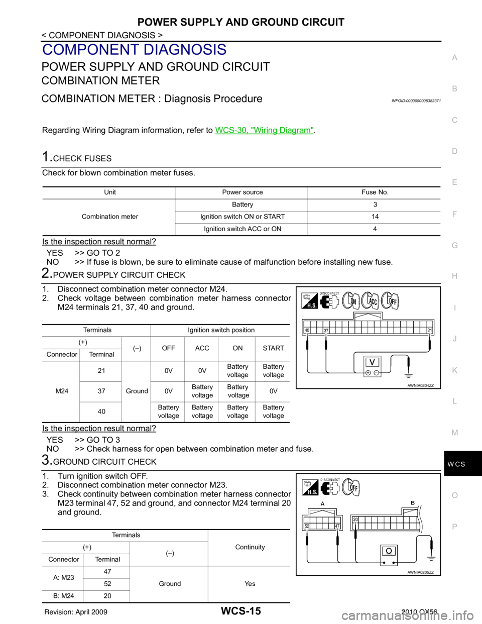
2.POWER SUPPLY CIRCUIT CHECK
1. Disconnect combination meter connector M24.
2. Check voltage between combination meter harness connector M24 terminals 21, 37, 40 and ground.
Is the inspection result normal?
YES >> GO TO 3
NO >> Check harness for open between combination meter and fuse.
3.GROUND CIRCUIT CHECK
1. Turn ignition switch OFF.
2. Disconnect combination meter connector M23.
3. Check continuity between combination meter harness connector M23 terminal 47, 52 and ground, and connector M24 terminal 20
and ground.
Unit Power source Fuse No.
Combination meter Battery 3
Ignition switch ON or START 14
Ignition switch ACC or ON 4
TerminalsIgnition switch position
(+) (–) OFF ACC ON START
Connector Terminal
M24 21
Ground 0V 0V
Battery
voltage Battery
voltage
37 0VBattery
voltage Battery
voltage 0V
40 Battery
voltage Battery
voltage Battery
voltage Battery
voltage
AWNIA0204ZZ
Te r m i n a l s
Continuity
(+)
(–)
Connector Terminal
A: M23 47
Ground Yes
52
B: M24 20
AWNIA0205ZZ
Revision: April 20092010 QX56
Page 4015 of 4210
WCS-16
< COMPONENT DIAGNOSIS >
POWER SUPPLY AND GROUND CIRCUIT
Is the inspection result normal?
YES >> Inspection End.
NO >> Check ground harness.
BCM (BODY CONTROL MODULE)
BCM (BODY CONTROL MODULE) : Diagnosis ProcedureINFOID:0000000005382372
Regarding Wiring Diagram information, refer to WCS-59, "Wiring Diagram".
1. CHECK FUSES AND FUSIBLE LINK
Check that the following fuses and fusible link are not blown.
Is the fuse blown?
YES >> Replace the blown fuse or fusible link after repairing the affected circuit.
NO >> GO TO 2
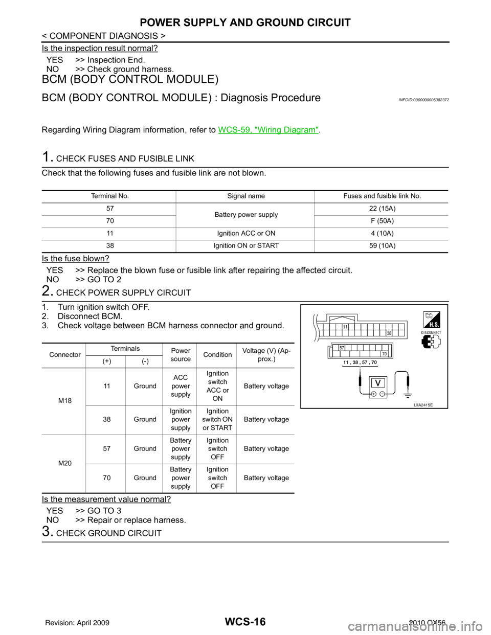
2. CHECK POWER SUPPLY CIRCUIT
1. Turn ignition switch OFF.
2. Disconnect BCM.
3. Check voltage between BCM harness connector and ground.
Is the measurement value normal?
YES >> GO TO 3
NO >> Repair or replace harness.
3. CHECK GROUND CIRCUIT
Terminal No. Signal nameFuses and fusible link No.
57 Battery power supply 22 (15A)
70 F (50A)
11 Ignition ACC or ON 4 (10A)
38 Ignition ON or START 59 (10A)
ConnectorTe r m i n a l s
Power
source Condition
Voltage (V) (Ap-
prox.)
(+) (-)
M18 11 Ground
ACC
power
supply Ignition
switch
ACC or ON Battery voltage
38 Ground Ignition
power
supply Ignition
switch ON or START Battery voltage
M20 57 Ground
Battery
power
supply Ignition
switch
OFF Battery voltage
70 Ground Battery
power
supply Ignition
switch OFF Battery voltage
LIIA2415E
Revision: April 20092010 QX56
Page 4018 of 4210
WCS
SEAT BELT BUCKLE SWITCH SIGNAL CIRCUIT
WCS-19
< COMPONENT DIAGNOSIS >
C
D E
F
G H
I
J
K L
M B A
O P
SEAT BELT BUCKLE SW ITCH SIGNAL CIRCUIT
DescriptionINFOID:0000000005146158
Transmits a seat belt buckle switch signal to the combination meter.
Component Function CheckINFOID:0000000005146159
1.CHECK COMBINATION METER INPUT SIGNAL
Select “DATA MONITOR” for “METER/M&A” and check the “SEAT BELT W/L” monitor value.
>> Inspection End.
Diagnosis ProcedureINFOID:0000000005146160
Regarding Wiring Diagram information, refer to WCS-23, "Wiring Diagram".
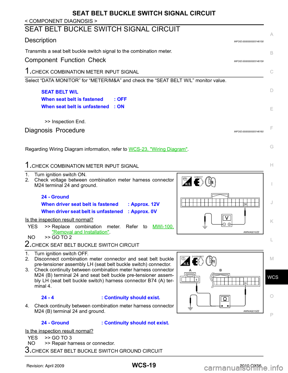
1.CHECK COMBINATION METER INPUT SIGNAL
1. Turn ignition switch ON.
2. Check voltage between combination meter harness connector M24 terminal 24 and ground.
Is the inspection result normal?
YES >> Replace combination meter. Refer to MWI-100,
"Removal and Installation".
NO >> GO TO 2
2.CHECK SEAT BELT BUCKLE SWITCH CIRCUIT
1. Turn ignition switch OFF.
2. Disconnect combination meter connector and seat belt buckle pre-tensioner assembly LH (seat belt buckle switch) connector.
3. Check continuity between combination meter harness connector M24 (B) terminal 24 and seat belt buckle pre-tensioner assem-
bly LH (seat belt buckle switch ) harness connector B74 (A) ter-
minal 4.
4. Check continuity between combination meter harness connector M24 (B) terminal 24 and ground.
Is the inspection result normal?
YES >> GO TO 3
NO >> Repair harness or connector.
3.CHECK SEAT BELT BUCKLE SWITCH GROUND CIRCUIT SEAT BELT W/L
When seat belt is fastened : OFF
When seat belt is unfastened : ON
24 - Ground
When driver seat belt is fastened : Approx. 12V
When driver seat belt is unfastened : Approx. 0V
AWNIA0212ZZ
24 - 4
: Continuity should exist.
24 - Ground : Continuity should not exist.
AWNIA0213ZZ
Revision: April 20092010 QX56