2010 INFINITI QX56 display
[x] Cancel search: displayPage 3561 of 4210
ON BOARD DIAGNOSTIC (OBD) SYSTEMSRC-15
< FUNCTION DIAGNOSIS >
C
DE
F
G
I
J
K L
M A
B
SRC
N
O P
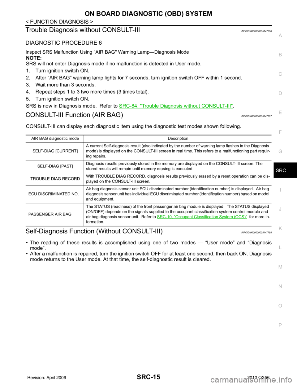
Trouble Diagnosis without CONSULT-IIIINFOID:0000000005147786
DIAGNOSTIC PROCEDURE 6
Inspect SRS Malfunction Using "AIR BAG" Warning Lamp—Diagnosis Mode
NOTE:
SRS will not enter Diagnosis mode if no malfunction is detected in User mode.
1. Turn ignition switch ON.
2. After “AIR BAG” warning lamp lights for 7 seconds, turn ignition switch OFF within 1 second.
3. Wait more than 3 seconds.
4. Repeat steps 1 to 3 two more times (3 times total).
5. Turn ignition switch ON.
SRS is now in Diagnosis mode. Refer to SRC-84, "
Trouble Diagnosis without CONSULT-III".
CONSULT-III Function (AIR BAG)INFOID:0000000005147787
CONSULT-III can display each diagnostic item using the diagnostic test modes shown following.
Self-Diagnosis Function (Without CONSULT-III)INFOID:0000000005147788
• The reading of these results is accomplished using one of two modes — “User mode” and “Diagnosis
mode”.
• After a malfunction is repaired, turn the ignition s witch OFF for at least one second, then back ON. Diagnosis
mode returns to the User mode. At that time, the self-diagnostic result is cleared.
AIR BAG diagnostic mode Description
SELF-DIAG [CURRENT] A current Self-diagnosis result (also indicated by the number of warning lamp flashes in the Diagnosis
mode) is displayed on the CONSULT-III screen in real
time. This refers to a malfunctioning part requir-
ing repairs.
SELF-DIAG [PAST] Diagnosis results previously stored in the memo
ry are displayed on the CONSULT-III screen. The
stored results will remain until memory erasing is executed.
TROUBLE DIAG RECORD With TROUBLE DIAG RECORD, diagnosis results previously erased by a reset operation can be dis-
played on the CONSULT-III screen.
ECU DISCRIMINATED NO. Air bag diagnosis sensor unit ECU discriminated number (identification number) is displayed. Air bag
diagnosis sensor unit has individual ECU discriminated number (identification number) based on model
and equipment.
PASSENGER AIR BAG The STATUS (readiness) of the front passenger air bag module is displayed. The STATUS displayed
(ON/OFF) depends on the signals supplied to the occupant classification system control module and
air bag diagnosis sensor unit. Refer to
SRC-10, "
Occupant Classification System (OCS)" for more in-
formation.
Revision: April 20092010 QX56
Page 3635 of 4210
SRS AIR BAG SYSTEMSRC-89
< SYMPTOM DIAGNOSIS >
C
DE
F
G
I
J
K L
M A
B
SRC
N
O P
SYMPTOM DIAGNOSIS
SRS AIR BAG SYSTEM
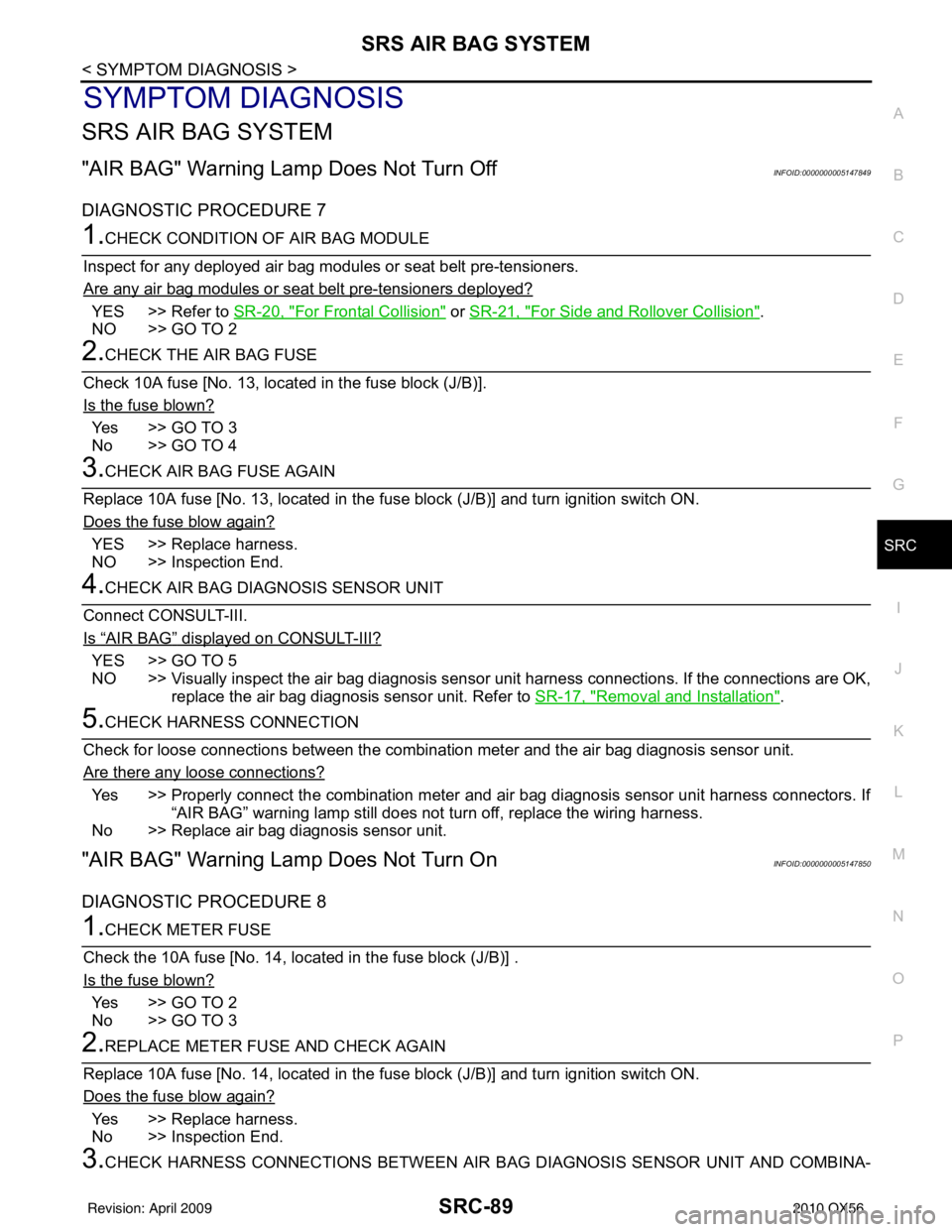
"AIR BAG" Warning Lamp Does Not Turn OffINFOID:0000000005147849
DIAGNOSTIC PROCEDURE 7
1.CHECK CONDITION OF AIR BAG MODULE
Inspect for any deployed air bag modules or seat belt pre-tensioners.
Are any air bag modules or seat belt pre-tensioners deployed?
YES >> Refer to SR-20, "For Frontal Collision" or SR-21, "For Side and Rollover Collision".
NO >> GO TO 2
2.CHECK THE AIR BAG FUSE
Check 10A fuse [No. 13, locat ed in the fuse block (J/B)].
Is the fuse blown?
Yes >> GO TO 3
No >> GO TO 4
3.CHECK AIR BAG FUSE AGAIN
Replace 10A fuse [No. 13, located in the fuse block (J/B)] and turn ignition switch ON.
Does the fuse blow again?
YES >> Replace harness.
NO >> Inspection End.
4.CHECK AIR BAG DIAGNOSIS SENSOR UNIT
Connect CONSULT-III.
Is
“AIR BAG” displayed on CONSULT-III?
YES >> GO TO 5
NO >> Visually inspect the air bag diagnosis sensor unit harness connections. If the connections are OK,
replace the air bag diagnosis sensor unit. Refer to SR-17, "
Removal and Installation".
5.CHECK HARNESS CONNECTION
Check for loose connections between the combination meter and the air bag diagnosis sensor unit.
Are there any loose connections?
Yes >> Properly connect the combination meter and air bag diagnosis sensor unit harness connectors. If “AIR BAG” warning lamp still does not turn off, replace the wiring harness.
No >> Replace air bag diagnosis sensor unit.
"AIR BAG" Warning La mp Does Not Turn OnINFOID:0000000005147850
DIAGNOSTIC PROCEDURE 8
1.CHECK METER FUSE
Check the 10A fuse [No. 14, loca ted in the fuse block (J/B)] .
Is the fuse blown?
Yes >> GO TO 2
No >> GO TO 3
2.REPLACE METER FUSE AND CHECK AGAIN
Replace 10A fuse [No. 14, located in the fuse block (J/B)] and turn ignition switch ON.
Does the fuse blow again?
Yes >> Replace harness.
No >> Inspection End.
3.CHECK HARNESS CONNECTIONS BETWEEN AIR BAG DIAGNOSIS SENSOR UNIT AND COMBINA-
Revision: April 20092010 QX56
Page 3701 of 4210
TM-6
< BASIC INSPECTION >
DIAGNOSIS AND REPAIR WORKFLOW
>> GO TO 3.
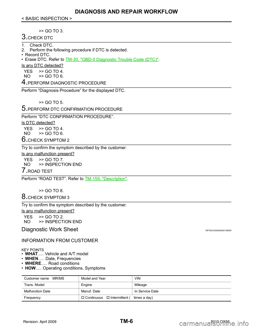
3.CHECK DTC
1. Check DTC.
2. Perform the following procedure if DTC is detected.
• Record DTC.
• Erase DTC. Refer to TM-30, "
OBD-II Diagnostic Trouble Code (DTC)".
Is any DTC detected?
YES >> GO TO 4.
NO >> GO TO 6.
4.PERFORM DIAGNOSTIC PROCEDURE
Perform “Diagnosis Procedure” for the displayed DTC.
>> GO TO 5.
5.PERFORM DTC CONFIRMATION PROCEDURE
Perform “DTC CONFIRMATION PROCEDURE”.
Is DTC detected?
YES >> GO TO 4.
NO >> GO TO 6.
6.CHECK SYMPTOM 2
Try to confirm the symptom described by the customer.
Is any malfunction present?
YES >> GO TO 7.
NO >> INSPECTION END
7.ROAD TEST
Perform “ROAD TEST”. Refer to TM-159, "
Description".
>> GO TO 8.
8.CHECK SYMPTOM 3
Try to confirm the symptom described by the customer.
Is any malfunction present?
YES >> GO TO 2.
NO >> INSPECTION END
Diagnostic Work SheetINFOID:0000000005148506
INFORMATION FROM CUSTOMER
KEY POINTS• WHAT ..... Vehicle and A/T model
• WHEN ..... Date, Frequencies
• WHERE ..... Road conditions
• HOW ..... Operating conditions, Symptoms
Customer name MR/MS Model and Year VIN
Trans. Model EngineMileage
Malfunction Date Manuf. DateIn Service Date
Frequency �† Continuous �† Intermittent ( times a day)
Revision: April 20092010 QX56
Page 3725 of 4210
TM-30
< FUNCTION DIAGNOSIS >
ON BOARD DIAGNOSTIC (OBD) SYSTEM
ON BOARD DIAGNOSTIC (OBD) SYSTEM
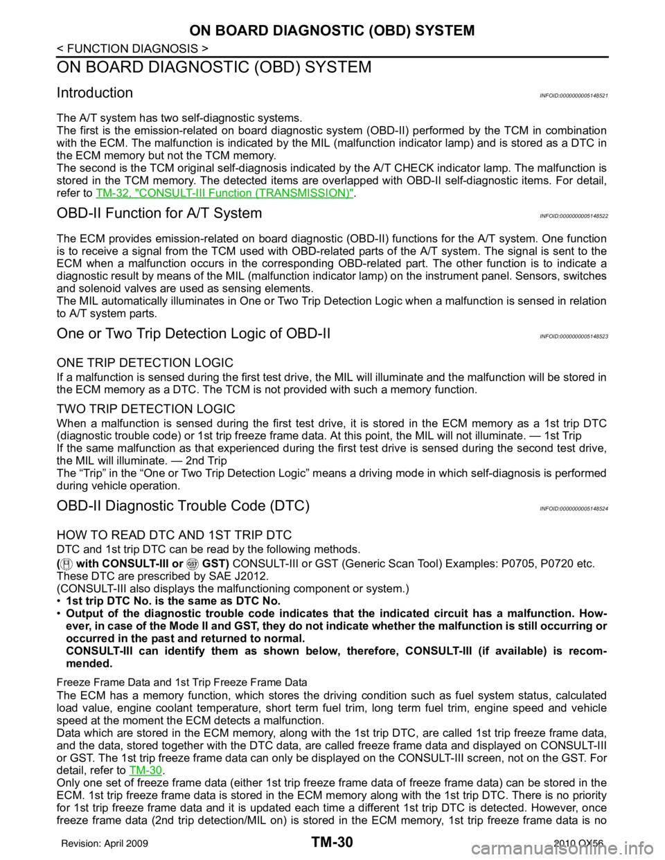
IntroductionINFOID:0000000005148521
The A/T system has two self-diagnostic systems.
The first is the emission-related on board diagnostic syst em (OBD-II) performed by the TCM in combination
with the ECM. The malfunction is indicated by the MI L (malfunction indicator lamp) and is stored as a DTC in
the ECM memory but not the TCM memory.
The second is the TCM original self-diagnosis indicated by the A/T CHECK indicator lamp. The malfunction is
stored in the TCM memory. The detected items are ov erlapped with OBD-II self-diagnostic items. For detail,
refer to TM-32, "
CONSULT-III Function (TRANSMISSION)".
OBD-II Function for A/T SystemINFOID:0000000005148522
The ECM provides emission-related on board diagnostic (O BD-II) functions for the A/T system. One function
is to receive a signal from the TCM used with OBD-relat ed parts of the A/T system. The signal is sent to the
ECM when a malfunction occurs in the corresponding OBD-re lated part. The other function is to indicate a
diagnostic result by means of the MIL (malfunction indi cator lamp) on the instrument panel. Sensors, switches
and solenoid valves are used as sensing elements.
The MIL automatically illuminates in One or Two Trip Detection Logic when a malfunction is sensed in relation
to A/T system parts.
One or Two Trip Detection Logic of OBD-IIINFOID:0000000005148523
ONE TRIP DETECTION LOGIC
If a malfunction is sensed during the first test drive, the MIL will illuminate and the malfunction will be stored in
the ECM memory as a DTC. The TCM is not provided with such a memory function.
TWO TRIP DETECTION LOGIC
When a malfunction is sensed during the first test drive, it is stored in the ECM memory as a 1st trip DTC
(diagnostic trouble code) or 1st trip freeze frame data. At this point, the MIL will not illuminate. — 1st Trip
If the same malfunction as that experienced during the fi rst test drive is sensed during the second test drive,
the MIL will illuminate. — 2nd Trip
The “Trip” in the “One or Two Trip Detection Logic” means a driving mode in which self-diagnosis is performed
during vehicle operation.
OBD-II Diagnostic Trouble Code (DTC)INFOID:0000000005148524
HOW TO READ DTC AND 1ST TRIP DTC
DTC and 1st trip DTC can be read by the following methods.
( with CONSULT-III or GST) CONSULT-III or GST (Generic Scan Tool) Examples: P0705, P0720 etc.
These DTC are prescribed by SAE J2012.
(CONSULT-III also displays the malfunctioning component or system.)
• 1st trip DTC No. is the same as DTC No.
• Output of the diagnostic troubl e code indicates that the indicated circuit has a malfunction. How-
ever, in case of the Mode II and GST, they do not indicate whether the malfunction is still occurring or
occurred in the past and returned to normal.
CONSULT-III can identify them as shown below, therefore, CONSULT-III (if available) is recom-
mended.
Freeze Frame Data and 1st Trip Freeze Frame Data
The ECM has a memory function, which stores the driv ing condition such as fuel system status, calculated
load value, engine coolant temperatur e, short term fuel trim, long term fuel trim, engine speed and vehicle
speed at the moment the ECM detects a malfunction.
Data which are stored in the ECM memory, along with the 1st trip DTC, are called 1st trip freeze frame data,
and the data, stored together with the DTC data, are called freeze frame data and displayed on CONSULT-III
or GST. The 1st trip freeze frame data can only be disp layed on the CONSULT-III screen, not on the GST. For
detail, refer to TM-30
.
Only one set of freeze frame data (either 1st trip freeze frame data of freeze frame data) can be stored in the
ECM. 1st trip freeze frame data is stored in the ECM memory along with the 1st trip DTC. There is no priority
for 1st trip freeze frame data and it is updated each time a different 1st trip DTC is detected. However, once
freeze frame data (2nd trip detection/MIL on) is stored in the ECM memory, 1st trip freeze frame data is no
Revision: April 20092010 QX56
Page 3727 of 4210
TM-32
< FUNCTION DIAGNOSIS >
DIAGNOSIS SYSTEM (TCM)
DIAGNOSIS SYSTEM (TCM)
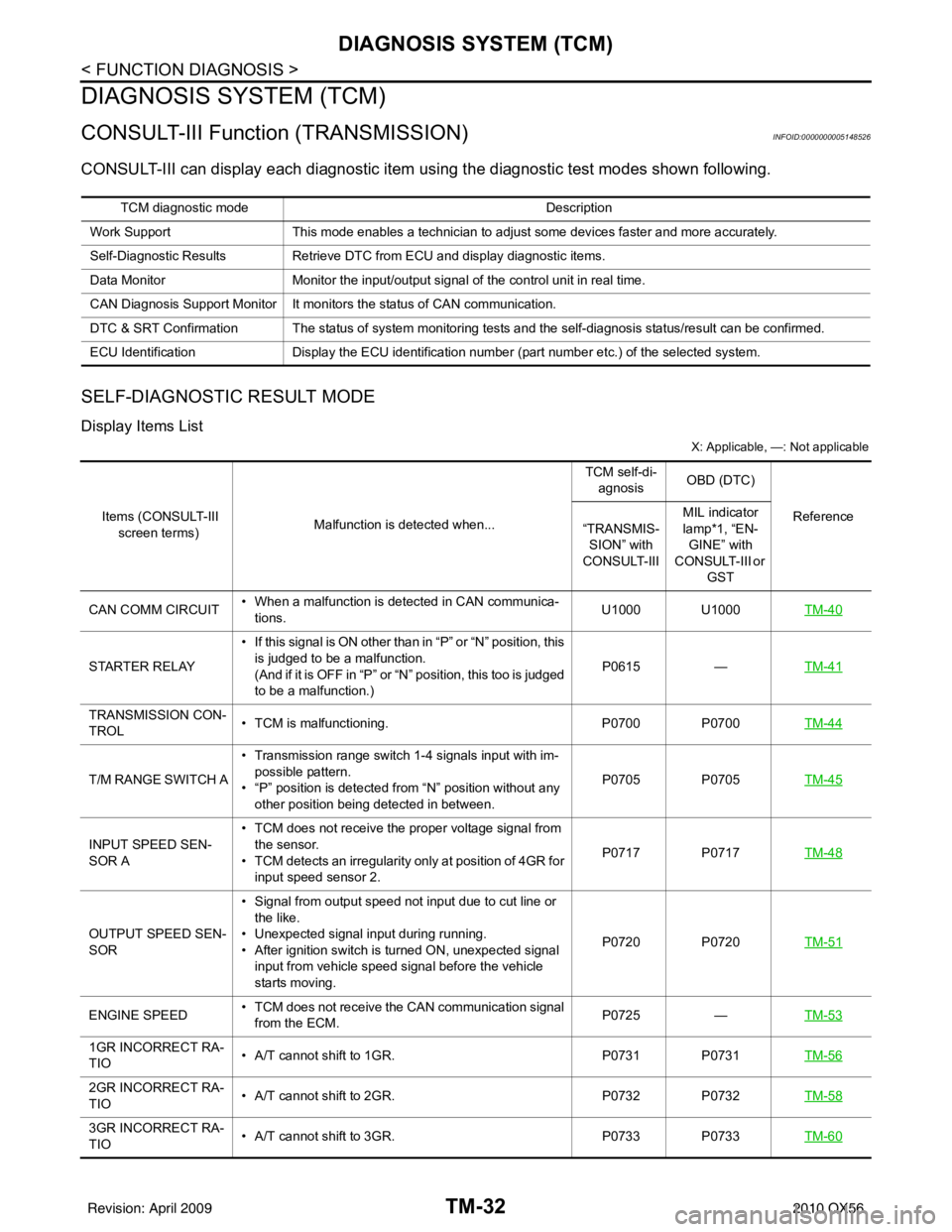
CONSULT-III Function (TRANSMISSION)INFOID:0000000005148526
CONSULT-III can display each diagnostic item us ing the diagnostic test modes shown following.
SELF-DIAGNOSTIC RESULT MODE
Display Items List
X: Applicable, —: Not applicable
TCM diagnostic mode Description
Work Support This mode enables a technician to adjust some devices faster and more accurately.
Self-Diagnostic Results Retrieve DTC from ECU and display diagnostic items.
Data Monitor Monitor the input/output signal of the control unit in real time.
CAN Diagnosis Support Monitor It monitors the status of CAN communication.
DTC & SRT Confirmation The status of system monitoring tests and the self-diagnosis status/result can be confirmed.
ECU Identification Display the ECU identification number (part number etc.) of the selected system.
Items (CONSULT-III
screen terms) Malfunction is detected when... TCM self-di-
agnosis OBD (DTC)
Reference
“TRANSMIS-
SION” with
CONSULT-III MIL indicator
lamp*1, “EN-
GINE” with
CONSULT-III or
GST
CAN COMM CIRCUIT • When a malfunction is detected in CAN communica-
tions. U1000 U1000
TM-40
STARTER RELAY• If this signal is ON other than in “P” or “N” position, this
is judged to be a malfunction.
(And if it is OFF in “P” or “N” position, this too is judged
to be a malfunction.) P0615
—TM-41
TRANSMISSION CON-
TROL • TCM is malfunctioning.
P0700 P0700TM-44
T/M RANGE SWITCH A• Transmission range switch 1-4 signals input with im-
possible pattern.
• “P” position is detected from “N” position without any other position being detected in between. P0705 P0705
TM-45
INPUT SPEED SEN-
SOR A• TCM does not receive the proper voltage signal from
the sensor.
• TCM detects an irregularity only at position of 4GR for input speed sensor 2. P0717 P0717
TM-48
OUTPUT SPEED SEN-
SOR• Signal from output speed not input due to cut line or
the like.
• Unexpected signal input during running.
• After ignition switch is turned ON, unexpected signal input from vehicle speed signal before the vehicle
starts moving. P0720 P0720
TM-51
ENGINE SPEED• TCM does not receive the CAN communication signal
from the ECM. P0725
—TM-53
1GR INCORRECT RA-
TIO • A/T cannot shift to 1GR.
P0731 P0731TM-56
2GR INCORRECT RA-
TIO• A/T cannot shift to 2GR.
P0732 P0732TM-58
3GR INCORRECT RA-
TIO• A/T cannot shift to 3GR.
P0733 P0733TM-60
Revision: April 20092010 QX56
Page 3729 of 4210
TM-34
< FUNCTION DIAGNOSIS >
DIAGNOSIS SYSTEM (TCM)
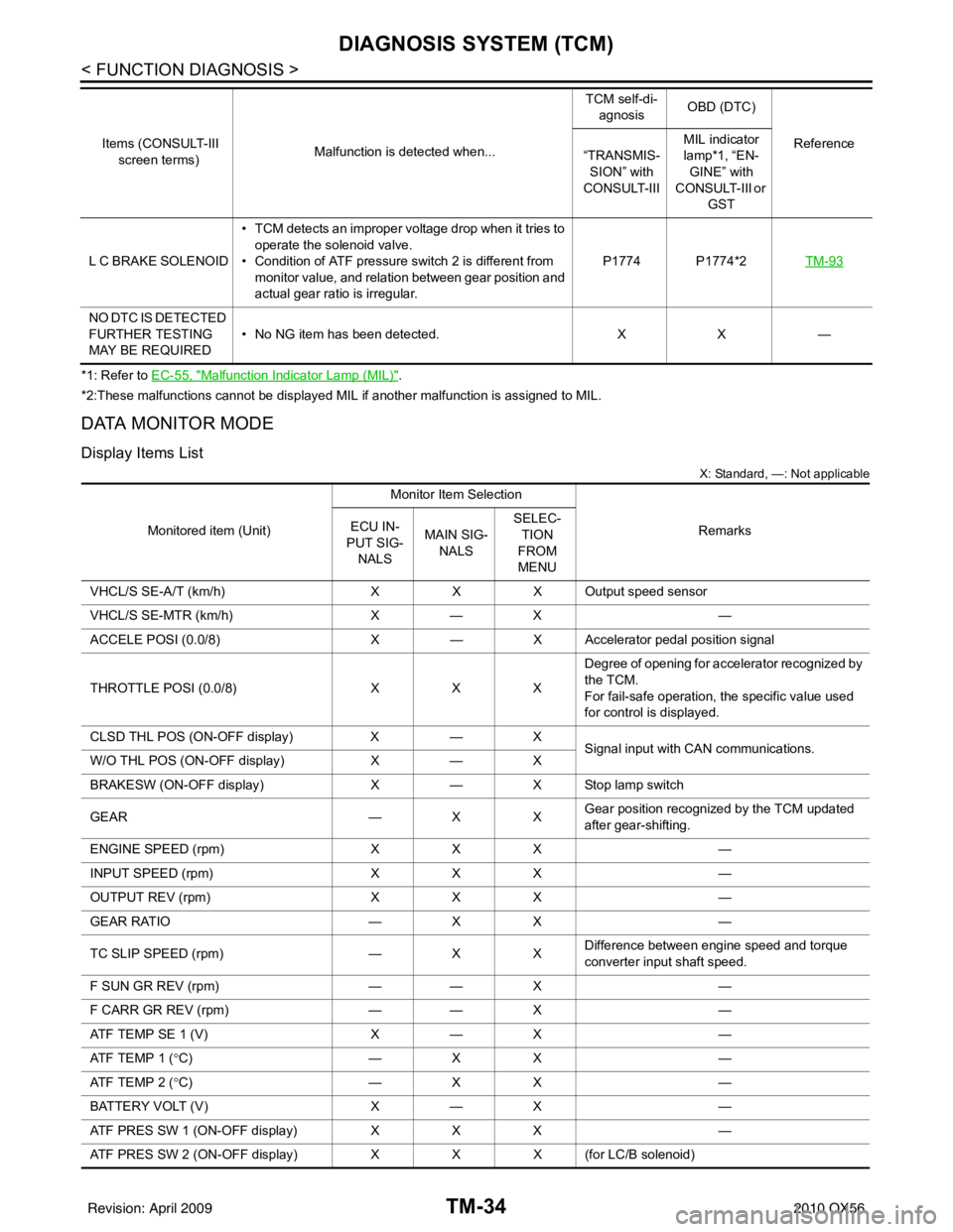
*1: Refer to EC-55, "Malfunction Indicator Lamp (MIL)".
*2:These malfunctions cannot be displayed MIL if another malfunction is assigned to MIL.
DATA MONITOR MODE
Display Items List
X: Standard, —: Not applicable
L C BRAKE SOLENOID • TCM detects an improper voltage drop when it tries to
operate the solenoid valve.
• Condition of ATF pressure switch 2 is different from
monitor value, and relation between gear position and
actual gear ratio is irregular. P1774 P1774*2
TM-93
NO DTC IS DETECTED
FURTHER TESTING
MAY BE REQUIRED• No NG item has been detected.
XX —
Items (CONSULT-III
screen terms) Malfunction is detected when... TCM self-di-
agnosis OBD (DTC)
Reference
“TRANSMIS-
SION” with
CONSULT-III MIL indicator
lamp*1, “EN-
GINE” with
CONSULT-III or
GST
Monitored item (Unit) Monitor Item Selection
Remarks
ECU IN-
PUT SIG-
NALS MAIN SIG-
NALS SELEC-
TION
FROM
MENU
VHCL/S SE-A/T (km/h) XXX Output speed sensor
VHCL/S SE-MTR (km/h) X— X —
ACCELE POSI (0.0/8) X— X Accelerator pedal position signal
THROTTLE POSI (0.0/8) XXXDegree of opening for accelerator recognized by
the TCM.
For fail-safe operation, the specific value used
for control is displayed.
CLSD THL POS (ON-OFF display) X— X
Signal input with CAN communications.
W/O THL POS (ON-OFF display) X— X
BRAKESW (ON-OFF display) X— X Stop lamp switch
GEAR —XXGear position recognized by the TCM updated
after gear-shifting.
ENGINE SPEED (rpm) XXX —
INPUT SPEED (rpm) XXX —
OUTPUT REV (rpm) XXX —
GEAR RATIO —XX —
TC SLIP SPEED (rpm) —XXDifference between engine speed and torque
converter input shaft speed.
F SUN GR REV (rpm) —— X —
F CARR GR REV (rpm) —— X —
ATF TEMP SE 1 (V) X— X —
ATF TEMP 1 (° C) —XX —
ATF TEMP 2 (° C) —XX —
BATTERY VOLT (V) X— X —
ATF PRES SW 1 (ON-OFF display) XXX —
ATF PRES SW 2 (ON-OFF display) XXX (for LC/B solenoid)
Revision: April 20092010 QX56
Page 3730 of 4210

DIAGNOSIS SYSTEM (TCM)TM-35
< FUNCTION DIAGNOSIS >
CEF
G H
I
J
K L
M A
B
TM
N
O P
ATF PRES SW 3 (ON-OFF display) XX X —
ATF PRES SW 5 (ON-OFF display) XX X —
ATF PRES SW 6 (ON-OFF display) XX X —
RANGE SW 1 (ON-OFF display) X— X —
RANGE SW 2 (ON-OFF display) X— X —
RANGE SW 3 (ON-OFF display) X— X —
RANGE SW 4 (ON-OFF display) X— X —
SLCT LVR POSI —XXSelector lever position is recognized by the TCM.
For fail-safe operation, the specific value used
for control is displayed.
1 POSITION SW (ON-OFF display) X— X 1st position switch
OD CONT SW (ON-OFF display) X— X 4th position switch
POWERSHIFT SW (ON-OFF display) X —X
Not mounted but displayed.
HOLD SW (ON-OFF display)
X— X
DS RANGE (ON-OFF display) —— X
MANU MODE SW (ON-OFF display) X— X
NON M-MODE SW (ON-OFF display) X —X
UP SW LEVER (ON-OFF display) X— X
DOWN SW LEVER (ON-OFF display) X —X
SFT UP ST SW (ON-OFF display) —— X
SFT DWN ST SW (ON-OFF display) — —X
ASCD-OD CUT (ON-OFF display) —— X —
ASCD-CRUISE (ON-OFF display) —— X —
ABS SIGNAL (ON-OFF display) —— X —
ACC OD CUT (ON-OFF display) —— X
ICC (Intelligent cruise control)
ACC SIGNAL (ON-OFF display) —— X
TCS GR/P KEEP (ON-OFF display) —— X —
TCS SIGNAL 2 (ON-OFF display) —— X —
TCS SIGNAL 1 (ON-OFF display) —— X —
TCC SOLENOID (A) —XX —
LINE PRES SOL (A) —XX —
I/C SOLENOID (A) —XX —
FR/B SOLENOID (A) —XX —
D/C SOLENOID (A) —XX —
HLR/C SOL (A) —XX —
ON OFF SOL (ON-OFF display) —— X LC/B solenoid
TCC SOL MON (A) —— X —
L/P SOL MON (A) —— X —
I/C SOL MON (A) —— X —
FR/B SOL MON (A) —— X —
D/C SOL MON (A) —— X —
HLR/C SOL MON (A) —— X —
Monitored item (Unit)
Monitor Item Selection
Remarks
ECU IN-
PUT SIG- NALS MAIN SIG-
NALS SELEC-
TION
FROM
MENU
Revision: April 20092010 QX56
Page 3731 of 4210

TM-36
< FUNCTION DIAGNOSIS >
DIAGNOSIS SYSTEM (TCM)
ONOFF SOL MON (ON-OFF display) ——X LC/B solenoid
P POSI IND (ON-OFF display) —— X —
R POSI IND (ON-OFF display) —— X —
N POSI IND (ON-OFF display) —— X —
D POSI IND (ON-OFF display) —— X —
4TH POSI IND (ON-OFF display) —— X —
3RD POSI IND (ON-OFF display) —— X —
2ND POSI IND (ON-OFF display) —— X —
1ST POSI IND (ON-OFF display) —— X —
MANU MODE IND (ON-OFF display) — —X
Not mounted but displayed.
POWER M LAMP (ON-OFF display) —— X
F-SAFE IND/L (ON-OFF display) —— X —
ATF WARN LAMP (ON-OFF display) — —X —
BACK-UP LAMP (ON-OFF display) —— X —
STARTER RELAY (ON-OFF display) — —X —
RANGE SW3M (ON-OFF display) —— X —
C/V CLB ID1 —— X —
C/V CLB ID2 —— X —
C/V CLB ID3 —— X —
UNIT CLB ID1 —— X —
UNIT CLB ID2 —— X —
UNIT CLB ID3 —— X —
TRGT GR RATIO —— X —
TRGT PRES TCC (kPa) —— X —
TRGT PRES L/P (kPa) —— X —
TRGT PRES I/C (kPa) —— X —
TRGT PRE FR/B (kPa) —— X —
TRGT PRES D/C (kPa) —— X —
TRG PRE HLR/C (kPa) —— X —
SHIFT PATTERN —— X —
DRV CST JUDGE —— X —
START RLY MON —— X —
NEXT GR POSI —— X —
SHIFT MODE —— X —
MANU GR POSI —— X —
VEHICLE SPEED (km/h) —XX Vehicle speed recognized by the TCM.
Voltage (V) —— XDisplays the value measured by the voltage
probe.
Monitored item (Unit)
Monitor Item Selection
Remarks
ECU IN-
PUT SIG- NALS MAIN SIG-
NALS SELEC-
TION
FROM
MENU
Revision: April 20092010 QX56