2010 INFINITI QX56 oil change
[x] Cancel search: oil changePage 3718 of 4210
A/T CONTROL SYSTEMTM-23
< FUNCTION DIAGNOSIS >
CEF
G H
I
J
K L
M A
B
TM
N
O P
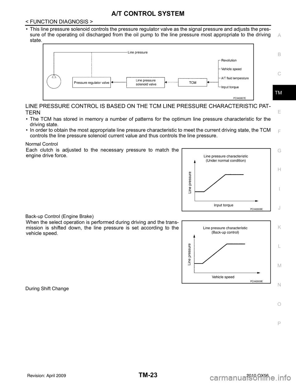
• This line pressure solenoid controls the pressure regulat or valve as the signal pressure and adjusts the pres-
sure of the operating oil discharged from the oil pump to the line pressure most appropriate to the driving
state.
LINE PRESSURE CONTROL IS BASED ON THE TCM LINE PRESSURE CHARACTERISTIC PAT-
TERN
• The TCM has stored in memory a number of patterns fo r the optimum line pressure characteristic for the
driving state.
• In order to obtain the most appropriate line pressure char acteristic to meet the current driving state, the TCM
controls the line pressure solenoid current value and thus controls the line pressure.
Normal Control
Each clutch is adjusted to the necessary pressure to match the
engine drive force.
Back-up Control (Engine Brake)
When the select operation is performed during driving and the trans-
mission is shifted down, the line pressure is set according to the
vehicle speed.
During Shift Change
PCIA0007E
PCIA0008E
PCIA0009E
Revision: April 20092010 QX56
Page 3719 of 4210
TM-24
< FUNCTION DIAGNOSIS >
A/T CONTROL SYSTEM
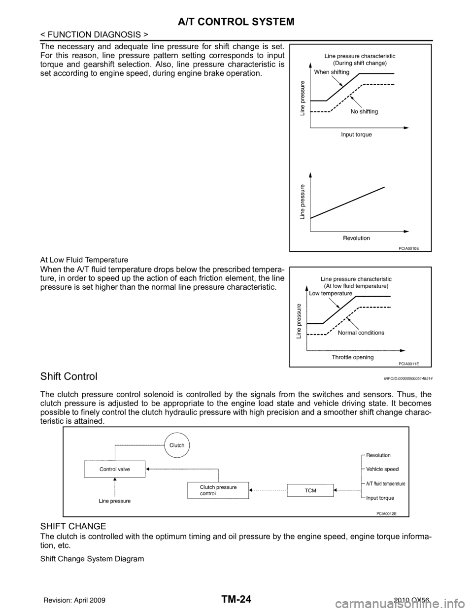
The necessary and adequate line pressure for shift change is set.
For this reason, line pressure pattern setting corresponds to input
torque and gearshift selection. Also, line pressure characteristic is
set according to engine speed, during engine brake operation.
At Low Fluid Temperature
When the A/T fluid temperature drops below the prescribed tempera-
ture, in order to speed up the action of each friction element, the line
pressure is set higher than the normal line pressure characteristic.
Shift ControlINFOID:0000000005148514
The clutch pressure control solenoid is controlled by the signals from the switches and sensors. Thus, the
clutch pressure is adjusted to be appropriate to the engine load state and vehicle driving state. It becomes
possible to finely control the clutch hydraulic pressure with high precision and a smoother shift change charac-
teristic is attained.
SHIFT CHANGE
The clutch is controlled with the optimum timing and oil pressure by the engine speed, engine torque informa-
tion, etc.
Shift Change System Diagram
PCIA0010E
PCIA0011E
PCIA0012E
Revision: April 20092010 QX56
Page 3720 of 4210
A/T CONTROL SYSTEMTM-25
< FUNCTION DIAGNOSIS >
CEF
G H
I
J
K L
M A
B
TM
N
O P
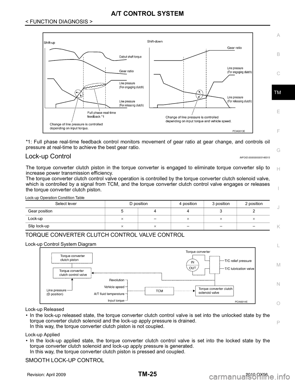
*1: Full phase real-time feedback control monitors move ment of gear ratio at gear change, and controls oil
pressure at real-time to achieve the best gear ratio.
Lock-up ControlINFOID:0000000005148515
The torque converter clutch piston in the torque conv erter is engaged to eliminate torque converter slip to
increase power transmission efficiency.
The torque converter clutch control valve operation is controlled by the torque conver ter clutch solenoid valve,
which is controlled by a signal from TCM, and the torque converter clutch control valve engages or releases
the torque converter clutch piston.
Lock-up Operation Condition Table
TORQUE CONVERTER CLUTCH CONTROL VALVE CONTROL
Lock-up Control System Diagram
Lock-up Released
• In the lock-up released state, the torque converter clutch control valve is set into the unlocked state by the
torque converter clutch solenoid and the lock-up apply pressure is drained.
In this way, the torque converter clutch piston is not coupled.
Lock-up Applied
• In the lock-up applied state, the torque converter clutch control valve is set into the locked state by the
torque converter clutch solenoid and lock-up apply pressure is generated.
In this way, the torque converter clutch piston is pressed and coupled.
SMOOTH LOCK-UP CONTROL
PCIA0013E
Select lever D position4 position 3 position 2 position
G ear p osit io n 54432
Lock-up ×– ×××
Slip lock-up ××–––
PCIA0014E
Revision: April 20092010 QX56
Page 3722 of 4210

A/T CONTROL SYSTEMTM-27
< FUNCTION DIAGNOSIS >
CEF
G H
I
J
K L
M A
B
TM
N
O P
FUNCTION OF PRESSURE SWITCH
Pilot valve A Adjusts the line pressure and produces the constant pressure (pilot pressure) required
for line pressure control, shift change control, and lock-up control.
Pilot valve B Adjusts the line pressure and produces the constant pressure (pilot pressure) required
for shift change control.
Low coast brake switching valve During engine braking, supplies the line pressure to the low coast brake reducing valve.
Low coast brake reducing valve When the low coast brake is coupled, adjusts the line pressure to the optimum pressure
(low coast brake pressure) and supplies it to the low coast brake.
N-R accumulator Produces the stabilizing pressure for when N-R is selected.
Direct clutch piston switching valve Operates in 4GR and switches the direct clutch coupling capacity.
High and low reverse clutch control valve When the high and low reverse clutch is coupled, adjusts the line pressure to the opti-
mum pressure (high and low reverse clutch pressure) and supplies it to the high and low
reverse clutch. (In 1GR, 3GR, 4GR and 5GR, adjusts the clutch pressure.)
Input clutch control valve When the input clutch is coupled, adjusts the line pressure to the optimum pressure (in-
put clutch pressure) and supplies it to the input clutch. (In 4GR and 5GR, adjusts the
clutch pressure.)
Direct clutch control valve When the direct clutch is coupled, adjusts the line pressure to the optimum pressure (di-
rect clutch pressure) and supplies it to the direct clutch. (In 2GR, 3GR, and 4GR, adjusts
the clutch pressure.)
TCC control valve
TCC control plug
TCC control sleeve Switches the lock-up to operating or released. Also, by performing the lock-up operation
transiently, lock-up smoothly.
Torque converter lubrication valve Operates during lock-up to switch the torque converter, cooling, and lubrication system
oil path.
Cool bypass valve Allows excess oil to bypass cooler circuit without being fed into it.
Line pressure relief valve Discharges excess oil from line pressure circuit.
N-D accumulator Produces the stabilizing pressure for when N-D is selected.
Manual valve Sends line pressure to each circuit according to the select position. The circuits to which
the line pressure is not sent drain.
Name
Function
Name Function
Pressure switch 2 (LC/B) Detects any malfunction in the low coast brake hydraulic pressure. When it detects any
malfunction, it puts the system into fail-safe mode.
Revision: April 20092010 QX56
Page 3824 of 4210
SYSTEM SYMPTOMTM-129
< SYMPTOM DIAGNOSIS >
CEF
G H
I
J
K L
M A
B
TM
N
O P
25
Slips/Will
Not en-
gage Does not hold lock-up
condition.
ON vehicle1. Fluid level and state
TM-148
2. Line pressure testTM-157
3. Engine speed signal TM-53
4. Input speed sensorTM-48
5. Torque converter clutch solenoid valveTM-65
6. CAN communication line LAN-4
7. Control valve with TCMTM-172
OFF vehicle8. Torque converter
TM-1729. Oil pump assemblyTM-172
26Lock-up is not re-
leased. ON vehicle1. Fluid level and state
TM-148
2. Line pressure testTM-157
3. Engine speed signal TM-53
4. Input speed sensorTM-48
5. Torque converter clutch solenoid valveTM-65
6. CAN communication line LAN-4
7. Control valve with TCMTM-172
OFF vehicle8. Torque converter
TM-1729. Oil pump assemblyTM-172
27No shock at all or the
clutch slips when vehi-
cle changes speed D1
→
D2. ON vehicle
1. Fluid level and state
TM-148
2. Output speed sensor and vehicle speed signal TM-50,
TM-76
3. Direct clutch solenoid valve TM-86
4. CAN communication line LAN-4
5. Line pressure testTM-157
6. Control valve with TCMTM-172
OFF vehicle7. Torque converter
TM-172
8. Oil pump assemblyTM-172
9. 3rd one-way clutchTM-172
10. Gear systemTM-172
11. Direct clutchTM-172
12. Forward brake (Parts behind drum support is impossible
to perform inspection by disassembly. Refer to TM-8
, TM-9. TM-172
No. Items
Symptom Condition Diagnostic ItemReference
page
Revision: April 20092010 QX56
Page 3825 of 4210

TM-130
< SYMPTOM DIAGNOSIS >
SYSTEM SYMPTOM
28Slips/Will
Not en-
gage No shock at all or the
clutch slips when vehi-
cle changes speed D2
→ D3.
ON vehicle
1. Fluid level and state
TM-148
2. Output speed sensor and vehicle speed signal TM-50,
TM-76
3. High and low reverse clutch solenoid valve TM-88
4. CAN communication line LAN-4
5. Line pressure testTM-157
6. Control valve with TCMTM-172
OFF vehicle7. Torque converter
TM-172
8. Oil pump assemblyTM-172
9. 3rd one-way clutchTM-172
10. Gear systemTM-172
11. High and low reverse clutchTM-172
12. Forward one- way clutch (Parts behind drum support is
impossible to perform inspection by disassembly. Refer to
TM-8
, TM-9. TM-172
13. Forward brake (Parts behind drum support is impossible
to perform inspection by disassembly. Refer to
TM-8
, TM-9. TM-172
29 No shock at all or the
clutch slips when vehi-
cle changes speed D3
→ D4. ON vehicle
1. Fluid level and state
TM-148
2. Output speed sensor and vehicle speed signal TM-50,
TM-76
3. Input clutch solenoid valve TM-82
4. Front brake solenoid valveTM-84
5. CAN communication line LAN-4
6. Line pressure testTM-157
7. Control valve with TCMTM-172
OFF vehicle8. Torque converter
TM-172
9. Oil pump assemblyTM-172
10. Input clutchTM-172
11. Gear systemTM-172
12. High and low reverse clutchTM-172
13. Direct clutchTM-172
No. ItemsSymptom Condition Diagnostic ItemReference
page
Revision: April 20092010 QX56
Page 3826 of 4210
SYSTEM SYMPTOMTM-131
< SYMPTOM DIAGNOSIS >
CEF
G H
I
J
K L
M A
B
TM
N
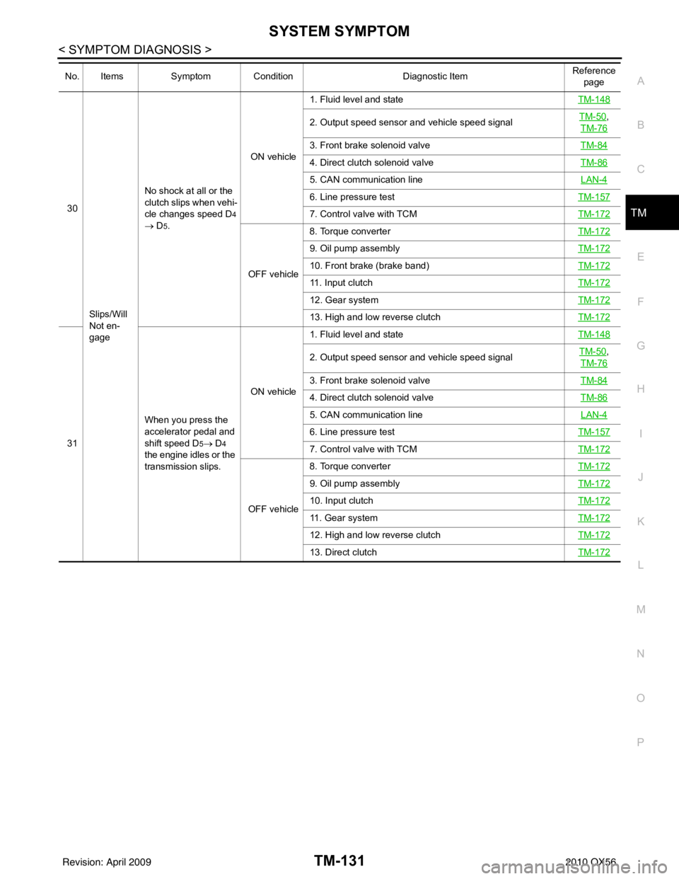
O P30
Slips/Will
Not en-
gage No shock at all or the
clutch slips when vehi-
cle changes speed D4
→
D5. ON vehicle
1. Fluid level and state
TM-148
2. Output speed sensor and vehicle speed signal TM-50,
TM-76
3. Front brake solenoid valve TM-84
4. Direct clutch solenoid valveTM-86
5. CAN communication line LAN-4
6. Line pressure testTM-157
7. Control valve with TCMTM-172
OFF vehicle8. Torque converter
TM-172
9. Oil pump assemblyTM-172
10. Front brake (brake band)TM-172
11. Input clutchTM-172
12. Gear systemTM-172
13. High and low reverse clutchTM-172
31When you press the
accelerator pedal and
shift speed D5→ D4
the engine idles or the
transmission slips. ON vehicle
1. Fluid level and state
TM-148
2. Output speed sensor and vehicle speed signal TM-50,
TM-76
3. Front brake solenoid valve TM-84
4. Direct clutch solenoid valveTM-86
5. CAN communication line LAN-4
6. Line pressure testTM-157
7. Control valve with TCMTM-172
OFF vehicle8. Torque converter
TM-172
9. Oil pump assemblyTM-172
10. Input clutchTM-172
11. Gear systemTM-172
12. High and low reverse clutchTM-172
13. Direct clutchTM-172
No. ItemsSymptom Condition Diagnostic ItemReference
page
Revision: April 20092010 QX56
Page 3867 of 4210
TM-172
< ON-VEHICLE REPAIR >
CONTROL VALVE WITH TCM
CONTROL VALVE WITH TCM
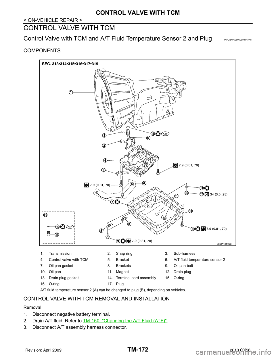
Control Valve with TCM and A/T Fluid Temperature Sensor 2 and PlugINFOID:0000000005148741
COMPONENTS
CONTROL VALVE WITH TCM REMOVAL AND INSTALLATION
Removal
1. Disconnect negative battery terminal.
2. Drain A/T fluid. Refer to TM-150, "
Changing the A/T Fluid (ATF)".
3. Disconnect A/T assembly harness connector.
1. Transmission 2. Snap ring3. Sub-harness
4. Control valve with TCM 5. Bracket 6. A/T fluid temperature sensor 2
7. Oil pan gasket 8. Brackets9. Oil pan bolt
10. Oil pan 11. Magnet12. Drain plug
13. Drain plug gasket 14. Terminal cord assembly 15. O-ring
16. O-ring 17. Plug
A/T fluid temperature sensor 2 (A) can be changed to plug (B), depending on vehicles.
JSDIA1314GB
Revision: April 20092010 QX56