2010 INFINITI QX56 oil change
[x] Cancel search: oil changePage 1760 of 4210
![INFINITI QX56 2010 Factory Service Manual IGNITION SIGNALEC-407
< COMPONENT DIAGNOSIS > [VK56DE]
C
D
E
F
G H
I
J
K L
M A
EC
NP
O
IGNITION SIGNAL
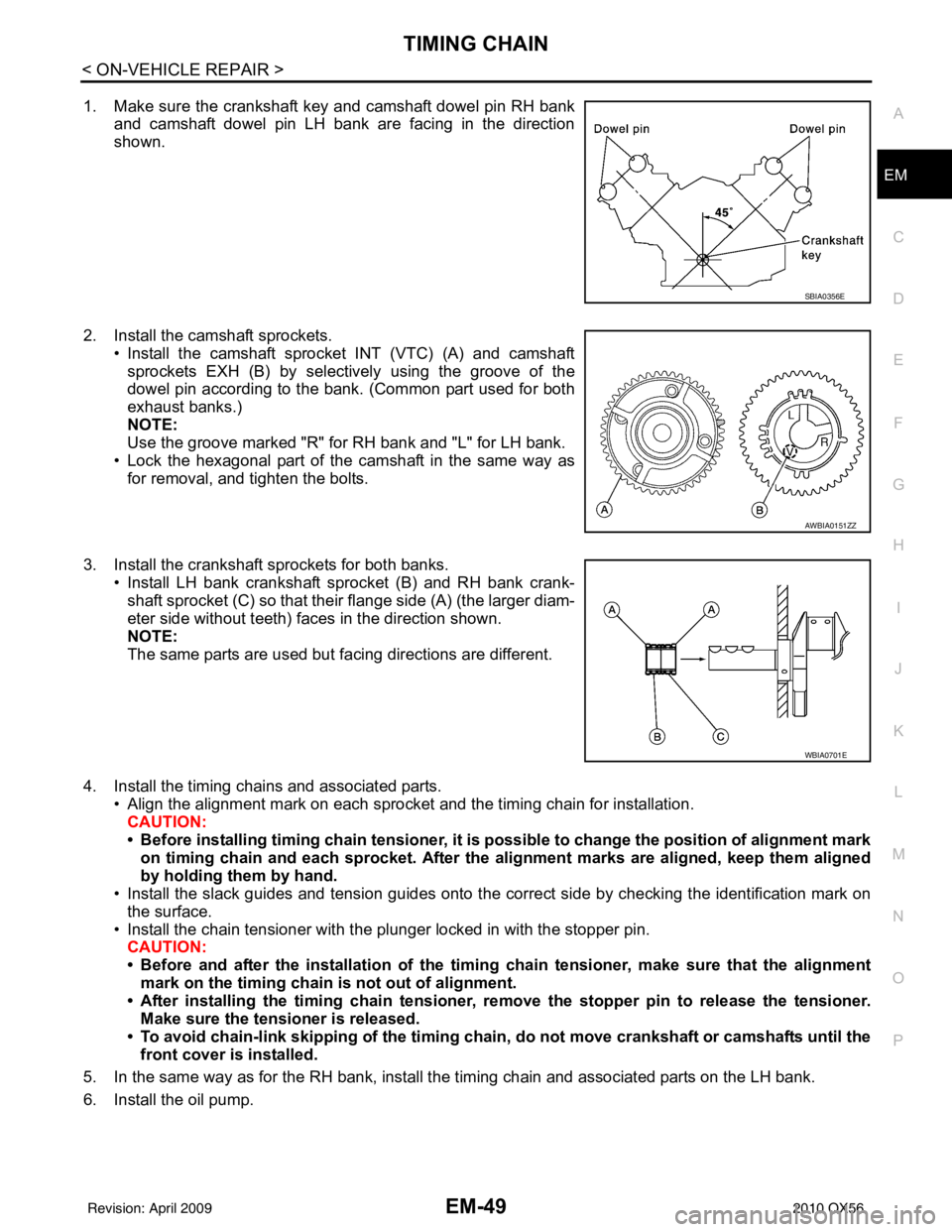
Component DescriptionINFOID:0000000005149482
IGNITION COIL & POWER TRANSISTOR
The ignition signal INFINITI QX56 2010 Factory Service Manual IGNITION SIGNALEC-407
< COMPONENT DIAGNOSIS > [VK56DE]
C
D
E
F
G H
I
J
K L
M A
EC
NP
O
IGNITION SIGNAL
Component DescriptionINFOID:0000000005149482
IGNITION COIL & POWER TRANSISTOR
The ignition signal](/manual-img/42/57032/w960_57032-1759.png)
IGNITION SIGNALEC-407
< COMPONENT DIAGNOSIS > [VK56DE]
C
D
E
F
G H
I
J
K L
M A
EC
NP
O
IGNITION SIGNAL
Component DescriptionINFOID:0000000005149482
IGNITION COIL & POWER TRANSISTOR
The ignition signal from the ECM is sent to and amplifi
ed by the power transistor. The power transistor turns
ON and OFF the ignition coil primary circuit. This ON/OFF operation induces the proper high voltage in the coil
secondary circuit.
Diagnosis ProcedureINFOID:0000000005149483
1.CHECK ENGINE START
Turn ignition switch OFF, and restart engine.
Is engine running?
Ye s o r N o
Yes (With CONSULT-III)>>GO TO 2.
Yes (Without CONSULT-III)>>GO TO 3.
No >> GO TO 4.
2.CHECK OVERALL FUNCTION
With CONSULT-III
1. Perform “POWER BALANCE” in “A CTIVE TEST” mode with CONSULT-III.
2. Make sure that each circuit produces a momentary engine speed drop.
OK or NG
OK >> INSPECTION END
NG >> GO TO 10.
3.CHECK OVERALL FUNCTION
Without CONSULT-III
1. Let engine idle.
2. Read the voltage signal between ECM terminals 46, 60, 61, 62, 65, 79, 80, 81 and ground with an oscilloscope.
3. Verify that the oscilloscope screen shows the signal wave as shown below.
NOTE:
The pulse cycle changes depending on rpm at idle.
OK or NG
1. Ignition coils (with power transistor) (bank 2) 2. Ignition coils (with power transistor)
(bank 1)
BBIA0777E
PBIB2094E
PBIB0044E
Revision: April 20092010 QX56
Page 1900 of 4210

TIMING CHAINEM-49
< ON-VEHICLE REPAIR >
C
DE
F
G H
I
J
K L
M A
EM
NP
O
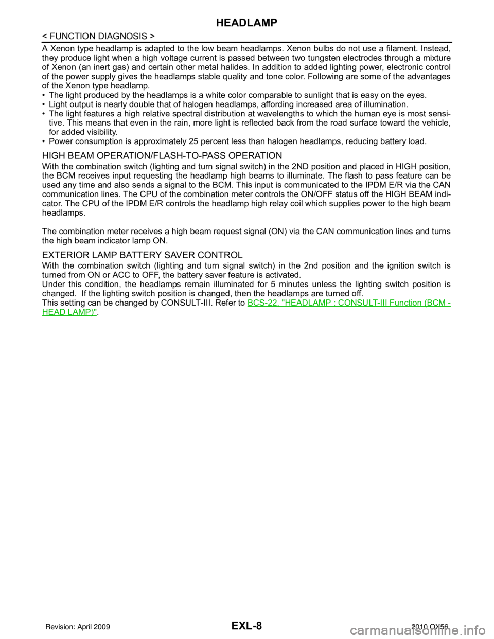
1. Make sure the crankshaft key and camshaft dowel pin RH bank
and camshaft dowel pin LH bank are facing in the direction
shown.
2. Install the camshaft sprockets. • Install the camshaft sprocket INT (VTC) (A) and camshaftsprockets EXH (B) by selectively using the groove of the
dowel pin according to the bank. (Common part used for both
exhaust banks.)
NOTE:
Use the groove marked "R" for RH bank and "L" for LH bank.
• Lock the hexagonal part of the camshaft in the same way as for removal, and tighten the bolts.
3. Install the crankshaft sprockets for both banks. • Install LH bank crankshaft sprocket (B) and RH bank crank-shaft sprocket (C) so that their flange side (A) (the larger diam-
eter side without teeth) faces in the direction shown.
NOTE:
The same parts are used but facing directions are different.
4. Install the timing chains and associated parts. • Align the alignment mark on each sprocket and the timing chain for installation.CAUTION:
• Before installing timing chain tensioner, it is possible to change the position of alignment mark
on timing chain and each sprocket . After the alignment marks are aligned, keep them aligned
by holding them by hand.
• Install the slack guides and tension guides onto the correct side by checking the identification mark on
the surface.
• Install the chain tensioner with t he plunger locked in with the stopper pin.
CAUTION:
• Before and after the installation of the timing chain tensioner, make sure that the alignment
mark on the timing chain is not out of alignment.
• After installing the timing chain tensioner, remove the stopp er pin to release the tensioner.
Make sure the tensioner is released.
• To avoid chain-link skipping of the timing chain, do not move crankshaft or camshafts until the
front cover is installed.
5. In the same way as for the RH bank, install the timing chain and associated parts on the LH bank.
6. Install the oil pump.
SBIA0356E
AWBIA0151ZZ
WBIA0701E
Revision: April 20092010 QX56
Page 1984 of 4210

EXL-8
< FUNCTION DIAGNOSIS >
HEADLAMP
A Xenon type headlamp is adapted to the low beam headlamps. Xenon bulbs do not use a filament. Instead,
they produce light when a high voltage current is pa ssed between two tungsten electrodes through a mixture
of Xenon (an inert gas) and certain other metal halides. In addition to added lighting power, electronic control
of the power supply gives the headlamps stable quality and tone color. Following are some of the advantages
of the Xenon type headlamp.
• The light produced by the headlamps is a white color comparable to sunlight that is easy on the eyes.
• Light output is nearly double that of halogen headlamps, affording increased area of illumination.
• The light features a high relative spectral distribution at wavelengths to which the human eye is most sensi- tive. This means that even in the rain, more light is reflected back from the road surface toward the vehicle,
for added visibility.
• Power consumption is approximately 25 percent less than halogen headlamps, reducing battery load.
HIGH BEAM OPERATION/FLASH-TO-PASS OPERATION
With the combination switch (lighting and turn signal switch) in the 2ND position and placed in HIGH position,
the BCM receives input requesting the headlamp high beams to illuminate. The flash to pass feature can be
used any time and also sends a signal to the BCM. This input is communicated to the IPDM E/R via the CAN
communication lines. The CPU of the combination meter c ontrols the ON/OFF status off the HIGH BEAM indi-
cator. The CPU of the IPDM E/R controls the headlamp high relay coil which supplies power to the high beam
headlamps.
The combination meter receives a high beam request signal (ON) via the CAN communication lines and turns
the high beam indicator lamp ON.
EXTERIOR LAMP BATTERY SAVER CONTROL
With the combination switch (lighting and turn signal switch) in the 2nd position and the ignition switch is
turned from ON or ACC to OFF, the battery saver feature is activated.
Under this condition, the headlamps remain illuminated for 5 minutes unless the lighting switch position is
changed. If the lighting switch position is changed, then the headlamps are turned off.
This setting can be changed by CONSULT-III. Refer to BCS-22, "
HEADLAMP : CONSULT-III Function (BCM -
HEAD LAMP)".
Revision: April 20092010 QX56
Page 2098 of 4210

EXL-122
< ECU DIAGNOSIS >
IPDM E/R (INTELLIGENT POWER DISTRIBUTION MODULE ENGINE ROOM)
IPDM E/R (INTELLIGENT POWER DISTRIBUTION MODULE ENGINE
ROOM)
Reference ValueINFOID:0000000005369897
VALUES ON THE DIAGNOSIS TOOL
Monitor Item ConditionValue/Status
MOTOR FAN REQ Engine idle speed Changes depending on engine
coolant temperature, air conditioner
operation status, vehicle speed,
etc.0 - 100 %
A/C COMP REQ A/C switch OFF
OFF
A/C switch ON ON
TAIL&CLR REQ Lighting switch OFF
OFF
Lighting switch 1ST, 2ND, HI or AUTO (Light is illuminated) ON
HL LO REQ Lighting switch OFF
OFF
Lighting switch 2ND HI or AUTO (Light is illuminated) ON
HL HI REQ Lighting switch OFF
OFF
Lighting switch HI ON
FR FOG REQ Lighting switch 2ND or AUTO (Light
is illuminated) Front fog lamp switch OFF OFF
• Front fog lamp switch ON
• Daytime light activated (Canada
only) ON
FR WIP REQ Ignition switch ON Front wiper switch OFF
STOP
Front wiper switch INT 1LOW
Front wiper switch LO LOW
Front wiper switch HI HI
WIP AUTO STOP Ignition switch ON Front wiper stop position
STOP P
Any position other than front wiper
stop position ACT P
WIP PROT Ignition switch ON Front wiper operates normally OFF
Front wiper stops at fail-safe opera-
tion
BLOCK
ST RLY REQ Ignition switch OFF or ACC
OFF
Ignition switch START ON
IGN RLY Ignition switch OFF or ACC
OFF
Ignition switch ON ON
RR DEF REQ Rear defogger switch OFF
OFF
Rear defogger switch ON ON
OIL P SW Ignition switch OFF, ACC or engine running
OPEN
Ignition switch ON CLOSE
DTRL REQ Daytime light system requested OFF with CONSULT-III.
OFF
Daytime light system requested ON with CONSULT-III. ON
HOOD SW Hood closed.
OFF
Hood open. ON
Revision: April 20092010 QX56
Page 2110 of 4210

EXL-134
< ECU DIAGNOSIS >
IPDM E/R (INTELLIGENT POWER DISTRIBUTION MODULE ENGINE ROOM)
If No CAN Communication Is Available With BCM
IGNITION RELAY MALFUNCTION DETECTION FUNCTION
• IPDM E/R monitors the voltage at the contact circuit and excitation coil circuit of the ignition relay inside it.
• IPDM E/R judges the ignition relay error if the voltage differs between the contact circuit and the excitation
coil circuit.
• If the ignition relay cannot turn OFF due to contact seizure, it activates the tail lamp relay for 10 minutes to alert the user to the ignition relay malfunction when the ignition switch is turned OFF.
NOTE:
The tail lamp turns OFF when the ignition switch is turned ON.
FRONT WIPER CONTROL
IPDM E/R detects front wiper stop posit ion by a front wiper auto stop signal.
When a front wiper auto stop signal is in the conditions listed below, IPDM E/R stops power supply to wiper
after repeating a front wiper 10 second activation and 20 second stop five times.
NOTE:
This operation status can be confirmed on the IPDM E/R “DATA MONITOR” that displays “Block” for the item
“WIP PROT” while the wiper is stopped.
STARTER MOTOR PROTECTION FUNCTION
IPDM E/R turns OFF the starter control relay to protect the starter motor when the starter control relay remains
active for 90 seconds.
Control part Fail-safe in operation
Cooling fan • Turns ON the cooling fan relay when the ignition switch is turned ON
• Turns OFF the cooling fan relay when the ignition switch is turned OFF
Control part
Fail-safe in operation
Headlamp • Turns ON the headlamp low relay when the ignition switch is turned ON
• Turns OFF the headlamp low relay when the ignition switch is turned OFF
• Headlamp high LH/RH relays OFF
•Parking lamps
• License plate lamps
• Tail lamps • Turns ON the tail lamp relay when the ignition switch is turned ON
• Turns OFF the tail lamp relay when the ignition switch is turned OFF
Front wiper • The status just before activation of fail-safe control is maintained until the ignition
switch is turned OFF while the front wiper is operating at LO or HI speed.
• The wiper is operated at LO speed until the ignition switch is turned OFF if the fail- safe control is activated while the front wipe r is set in the INT mode and the front wiper
motor is operating.
Rear window defogger Rear window defogger relay OFF
A/C compressor A/C relay OFF
Front fog lamps Front fog lamp relay OFF
Ignition switch Ignition relayTail lamp relay
ON ON —
OFF OFF —
Ignition switchFront wiper switch Auto stop signal
ON OFF
Front wiper stop position signal cannot be
input 10 seconds.
ON The signal does not change for 10 seconds.
Revision: April 20092010 QX56
Page 2258 of 4210

SERVICE INFORMATION FOR ELECTRICAL INCIDENTGI-35
< BASIC INSPECTION >
C
DE
F
G H
I
J
K L
M B
GI
N
O P
• Do not apply excessive shock to the control unit by dropping or hit- ting it.
• Be careful to prevent condensation in the control unit due to rapid
temperature changes and do not let water or rain get on it. If water
is found in the control unit, dry it fully and then install it in the vehi-
cle.
• Be careful not to let oil to get on the control unit connector.
• Avoid cleaning the control unit with volatile oil.
• Do not disassemble the control unit, and do not remove the upper and lower covers.
• When using a DMM, be careful not to let test probes get close to each other to prevent the power transistor in the control unit from
damaging battery voltage because of short circuiting.
• When checking input and output signals of the control unit, use the specified check adapter.
How to Check TerminalINFOID:0000000005149606
CONNECTOR AND TERMINAL PIN KIT
• Use the connector and terminal pin kits listed below when replacing connectors or terminals.
• The connector and terminal pin kits contain some of the most commonly used NISSAN/INFINITI connectors
and terminals. For detailed connector and terminal pin r eplacement procedures, refer to the latest NISSAN/
INFINITI CONNECTOR AND TERMINAL PIN SERVICE MANUAL.
SAIA0255E
SEF348N
Revision: April 20092010 QX56
Page 2305 of 4210

PREPARATIONHA-13
< PREPARATION >
C
DE
F
G H
J
K L
M A
B
HA
N
O P
PREPARATION
PREPARATION
Special Service ToolINFOID:0000000005147639
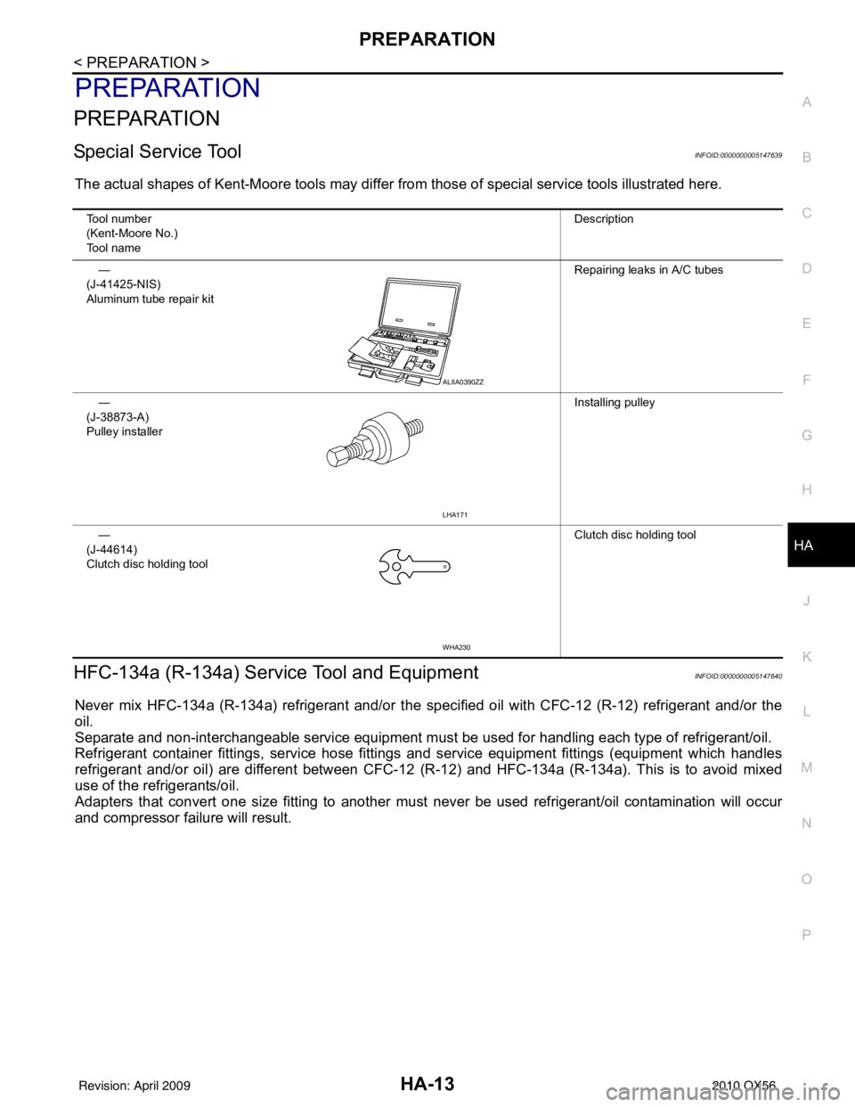
The actual shapes of Kent-Moore tools may differ from those of special service tools illustrated here.
HFC-134a (R-134a) Service Tool and EquipmentINFOID:0000000005147640
Never mix HFC-134a (R-134a) refrigerant and/or the specified oil with CFC-12 (R-12) refrigerant and/or the
oil.
Separate and non-interchangeable service equipment must be used for handling each type of refrigerant/oil.
Refrigerant container fittings, service hose fittings and service equipment fittings (equipment which handles
refrigerant and/or oil) are different between CFC-12 (R-12) and HFC-134a (R-134a). This is to avoid mixed
use of the refrigerants/oil.
Adapters that convert one size fitting to another must never be used refrigerant/oil contamination will occur
and compressor failure will result.
Tool number
(Kent-Moore No.)
Tool name Description
—
(J-41425-NIS)
Aluminum tube repair kit Repairing leaks in A/C tubes
—
(J-38873-A)
Pulley installer Installing pulley
—
(J-44614)
Clutch disc holding tool Clutch disc holding tool
ALIIA0390ZZ
LHA171
WHA230
Revision: April 20092010 QX56
Page 2311 of 4210

OIL
HA-19
< FUNCTION DIAGNOSIS >
C
D E
F
G H
J
K L
M A
B
HA
N
O P
OIL
Maintenance of Oil in CompressorINFOID:0000000005147644
The oil in the compressor circulates through the system with the refrigerant. Add oil to compressor when
replacing any component or after a large refrigerant leakage has occurred. It is important to maintain the spec-
ified amount.
If oil quantity is not maintained properly , the following malfunctions may result:
• Lack of oil: May lead to a seized compressor
• Excessive oil: Inadequate cooling (thermal exchange interference)
Revision: April 20092010 QX56