2010 INFINITI QX56 oil change
[x] Cancel search: oil changePage 2314 of 4210
HA-22
< ON-VEHICLE MAINTENANCE >
OIL
OIL
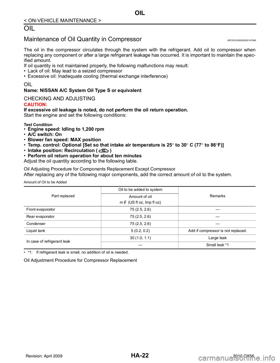
Maintenance of Oil Quantity in CompressorINFOID:0000000005147646
The oil in the compressor circulates through the system with the refrigerant. Add oil to compressor when
replacing any component or after a large refrigerant leakage has occurred. It is important to maintain the spec-
ified amount.
If oil quantity is not maintained properly, the following malfunctions may result:
• Lack of oil: May lead to a seized compressor
• Excessive oil: Inadequate cooling (thermal exchange interference)
OIL
Name: NISSAN A/C System Oil Type S or equivalent
CHECKING AND ADJUSTING
CAUTION:
If excessive oil leakage is noted, do not perform the oil return operation.
Start the engine and set the following conditions:
Test Condition
• Engine speed: Idling to 1,200 rpm
• A/C switch: On
• Blower fan speed: MAX position
• Temp. control: Optional [Set so that intake air temperature is 25 ° to 30 ° C (77 ° to 86 °F)]
• Intake position: Recirculation ( )
• Perform oil return operation for about ten minutes
Adjust the oil quantity according to the following table.
Oil Adjusting Procedure for Components Replacement Except Compressor
After replacing any of the following major components, add the correct amount of oil to the system.
Amount of Oil to be Added
• *1: If refrigerant leak is small, no addition of oil is needed.
Oil Adjustment Procedure for Compressor Replacement
Part replaced Oil to be added to system
Remarks
Amount of oil
m (US fl oz, Imp fl oz)
Front evaporator 75 (2.5, 2.6)—
Rear evaporator 75 (2.5, 2.6)—
Condenser 75 (2.5, 2.6)—
Liquid tank 5 (0.2, 0.2)Add if compressor is not replaced.
In case of refrigerant leak 30 (1.0, 1.1)
Large leak
— Small leak *1
Revision: April 20092010 QX56
Page 2453 of 4210
![INFINITI QX56 2010 Factory Service Manual INSUFFICIENT COOLINGHAC-113
< SYMPTOM DIAGNOSIS > [AUTOMATIC AIR CONDITIONER]
C
D
E
F
G H
J
K L
M A
B
HAC
N
O P
dard (usual) pressure, however, differs from vehicle to vehicle, refer to above table (A INFINITI QX56 2010 Factory Service Manual INSUFFICIENT COOLINGHAC-113
< SYMPTOM DIAGNOSIS > [AUTOMATIC AIR CONDITIONER]
C
D
E
F
G H
J
K L
M A
B
HAC
N
O P
dard (usual) pressure, however, differs from vehicle to vehicle, refer to above table (A](/manual-img/42/57032/w960_57032-2452.png)
INSUFFICIENT COOLINGHAC-113
< SYMPTOM DIAGNOSIS > [AUTOMATIC AIR CONDITIONER]
C
D
E
F
G H
J
K L
M A
B
HAC
N
O P
dard (usual) pressure, however, differs from vehicle to vehicle, refer to above table (Ambient air temperature-
to-operating pressure table).
Both High- and Low-pressure Sides are Too High
High-pressure Side is Too High and Low-pressure Side is Too Low
High-pressure Side is Too Low and Low-pressure Side is Too High
Gauge indication Refrigerant cycleProbable causeCorrective action
Both high- and low-pressure sides
are too high. Pressure is reduced soon af-
ter water is splashed on con-
denser.
Excessive refrigerant charge in
refrigeration cycle
Reduce refrigerant until speci-
fied pressure is obtained.
Air suction by cooling fan is in-
sufficient. Insufficient condenser cooling
performance
↓
1. Condenser fins are
clogged.
2. Improper fan rotation of
cooling fan • Clean condenser.
• Check and repair cooling fan
if necessary.
• Low-pressure pipe is not cold.
• When compressor is
stopped high-pressure val-
ue quickly drops by approx-
imately 196 kPa (2 kg/cm
2 ,
28 psi). It then decreases
gradually thereafter. Poor heat exchange in con-
denser
(After compressor operation
stops, high-pressure decreas-
es too slowly.)
↓
Air in refrigeration cycle
Evacuate and recharge system.
Engine tends to overheat. Engine cooling systems mal-
function. Check and repair engine cool-
ing system.
• An area of the low-pressure pipe is colder than areas
near the evaporator outlet.
• Plates are sometimes cov- ered with frost. • Excessive liquid refrigerant
on low-pressure side
• Excessive refrigerant dis-
charge flow
• Expansion valve is open a lit- tle compared with the speci-
fication.
↓
Improper expansion valve ad-
justment Replace expansion valve.
AC359A
Gauge indication
Refrigerant cycleProbable causeCorrective action
High-pressure side is too high and
low-pressure side is too low. Upper side of condenser and
high-pressure side are hot,
however, liquid tank is not so
hot.High-pressure tube or parts lo-
cated between compressor
and condenser are clogged or
crushed.
• Check and repair or replace
malfunctioning parts.
• Check oil for contamination.
AC360A
Revision: April 20092010 QX56
Page 2478 of 4210
ILLUMINATION CONTROL SYSTEMINL-9
< FUNCTION DIAGNOSIS >
C
DE
F
G H
I
J
K
M A
B
INL
N
O P
ILLUMINATION CONTROL SYSTEM
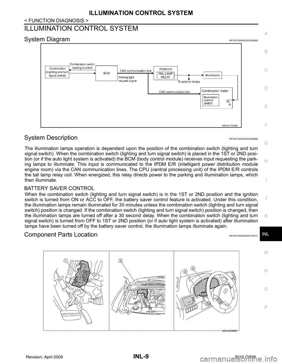
System DiagramINFOID:0000000005358668
System DescriptionINFOID:0000000005358669
The illumination lamps operation is dependent upon the posit ion of the combination switch (lighting and turn
signal switch). When the combination switch (lighting and turn signal switch) is placed in the 1ST or 2ND posi-
tion (or if the auto light system is activated) the BCM (body control modul e) receives input requesting the park-
ing lamps to illuminate. This input is communicated to the IPDM E/R (intelligent power distribution module
engine room) via the CAN communication lines. The CPU (central processing unit) of the IPDM E/R controls
the tail lamp relay coil. When energized, this relay directs power to the parking and illumination lamps, which
then illuminate.
BATTERY SAVER CONTROL
When the combination switch (lighting and turn signal s witch) is in the 1ST or 2ND position and the ignition
switch is turned from ON or ACC to OFF, the battery saver control feature is activated. Under this condition,
the illumination lamps remain illuminated for 30 minutes unless the combination switch (lighting and turn signal
switch) position is changed. If the combination switch (lighting and turn signal switch) position is changed, then
the illumination lamps are turned off after a 30 second delay. When the combination switch (lighting and turn
signal switch) is turned from OFF to 1ST or 2ND position (or if auto light system is activated) after illumination
lamps have been turned off by the battery saver c ontrol, the illumination lamps illuminate again.
Component Parts LocationINFOID:0000000005146721
AWLIA1754GB
AWLIA0398ZZ
Revision: April 20092010 QX56
Page 2696 of 4210
LU-10
< ON-VEHICLE MAINTENANCE >
ENGINE OIL
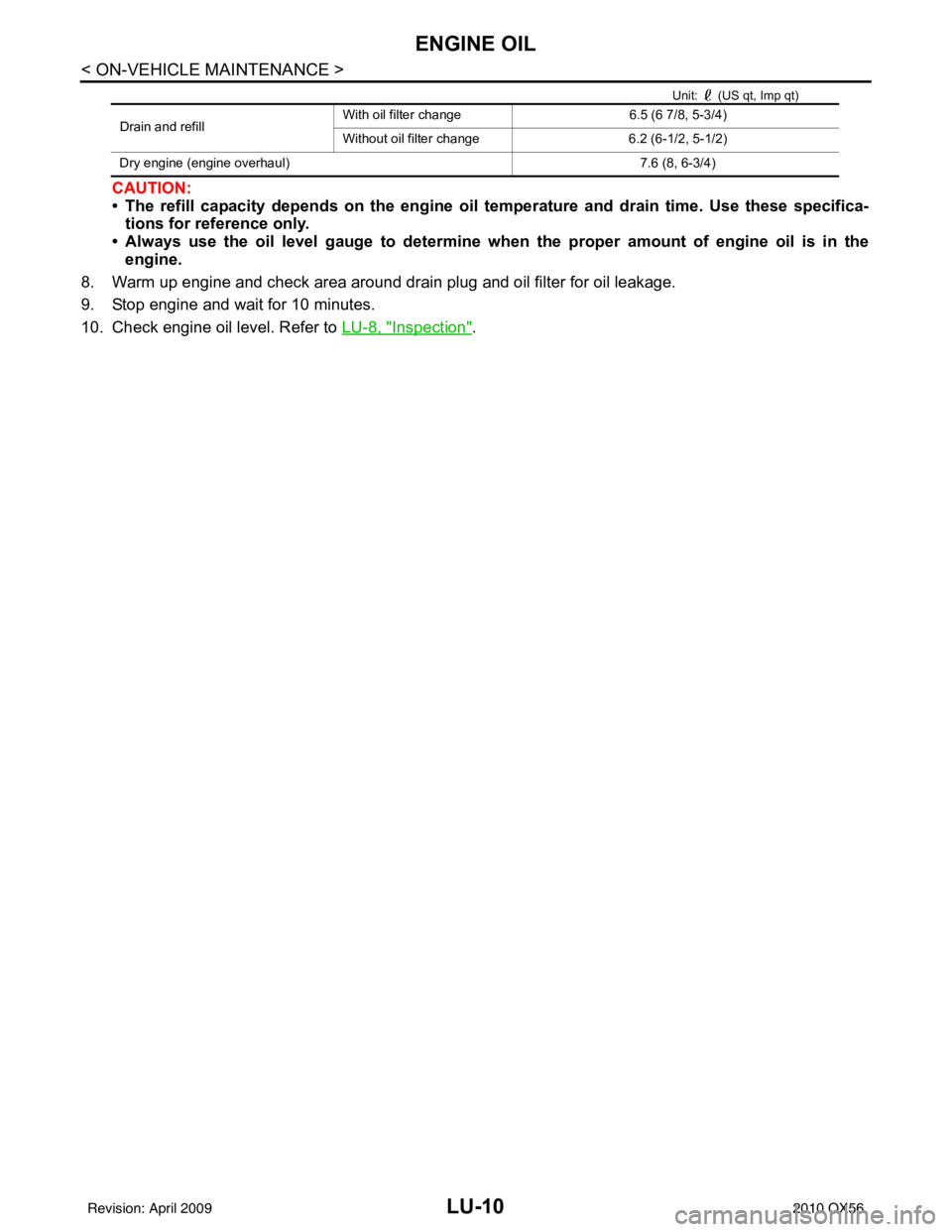
Unit: (US qt, Imp qt)
CAUTION:
• The refill capacity depends on the engine oil temperature and drain time. Use these specifica-
tions for reference only.
• Always use the oil level gauge to determine when the proper amount of engine oil is in the engine.
8. Warm up engine and check area around drain plug and oil filter for oil leakage.
9. Stop engine and wait for 10 minutes.
10. Check engine oil level. Refer to LU-8, "
Inspection".
Drain and refill With oil filter change
6.5 (6 7/8, 5-3/4)
Without oil filter change 6.2 (6-1/2, 5-1/2)
Dry engine (engine overhaul) 7.6 (8, 6-3/4)
Revision: April 20092010 QX56
Page 2704 of 4210
LU-18
< SERVICE DATA AND SPECIFICATIONS (SDS)
SERVICE DATA AND SPECIFICATIONS (SDS)
SERVICE DATA AND SPECIFICATIONS (SDS)
SERVICE DATA AND SPECIFICATIONS (SDS)
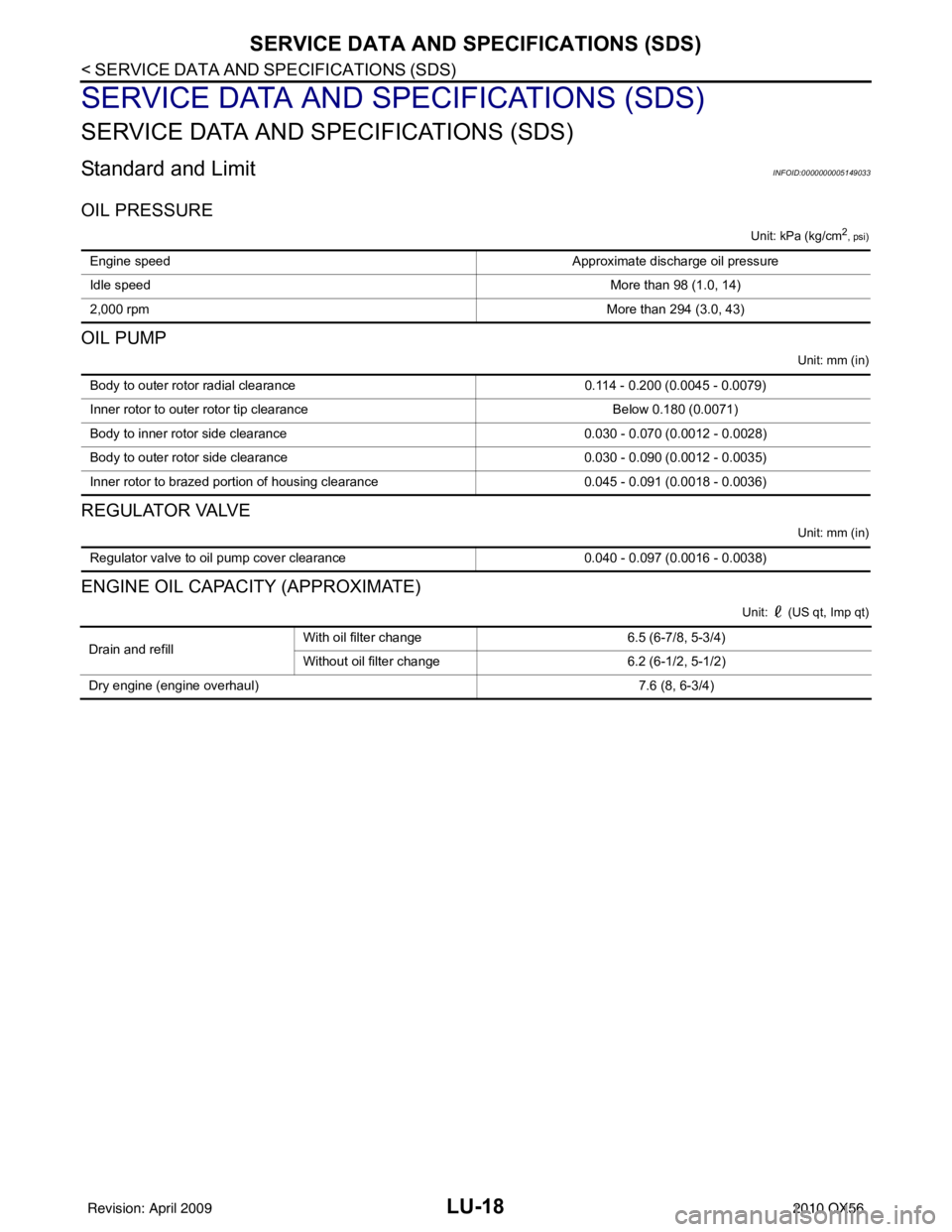
Standard and LimitINFOID:0000000005149033
OIL PRESSURE
Unit: kPa (kg/cm2, psi)
OIL PUMP
Unit: mm (in)
REGULATOR VALVE
Unit: mm (in)
ENGINE OIL CAPACITY (APPROXIMATE)
Unit: (US qt, Imp qt)
Engine speed Approximate discharge oil pressure
Idle speed More than 98 (1.0, 14)
2,000 rpm More than 294 (3.0, 43)
Body to outer rotor radial clearance0.114 - 0.200 (0.0045 - 0.0079)
Inner rotor to outer rotor tip clearance Below 0.180 (0.0071)
Body to inner rotor side clearance 0.030 - 0.070 (0.0012 - 0.0028)
Body to outer rotor side clearance 0.030 - 0.090 (0.0012 - 0.0035)
Inner rotor to brazed portion of housing clearance 0.045 - 0.091 (0.0018 - 0.0036)
Regulator valve to oil pump cover clearance 0.040 - 0.097 (0.0016 - 0.0038)
Drain and refillWith oil filter change 6.5 (6-7/8, 5-3/4)
Without oil filter change
6.2 (6-1/2, 5-1/2)
Dry engine (engine overhaul) 7.6 (8, 6-3/4)
Revision: April 20092010 QX56
Page 2715 of 4210
PERIODIC MAINTENANCEMA-11
< ON-VEHICLE MAINTENANCE >
C
DE
F
G H
I
J
K L
M B
MA
N
O A
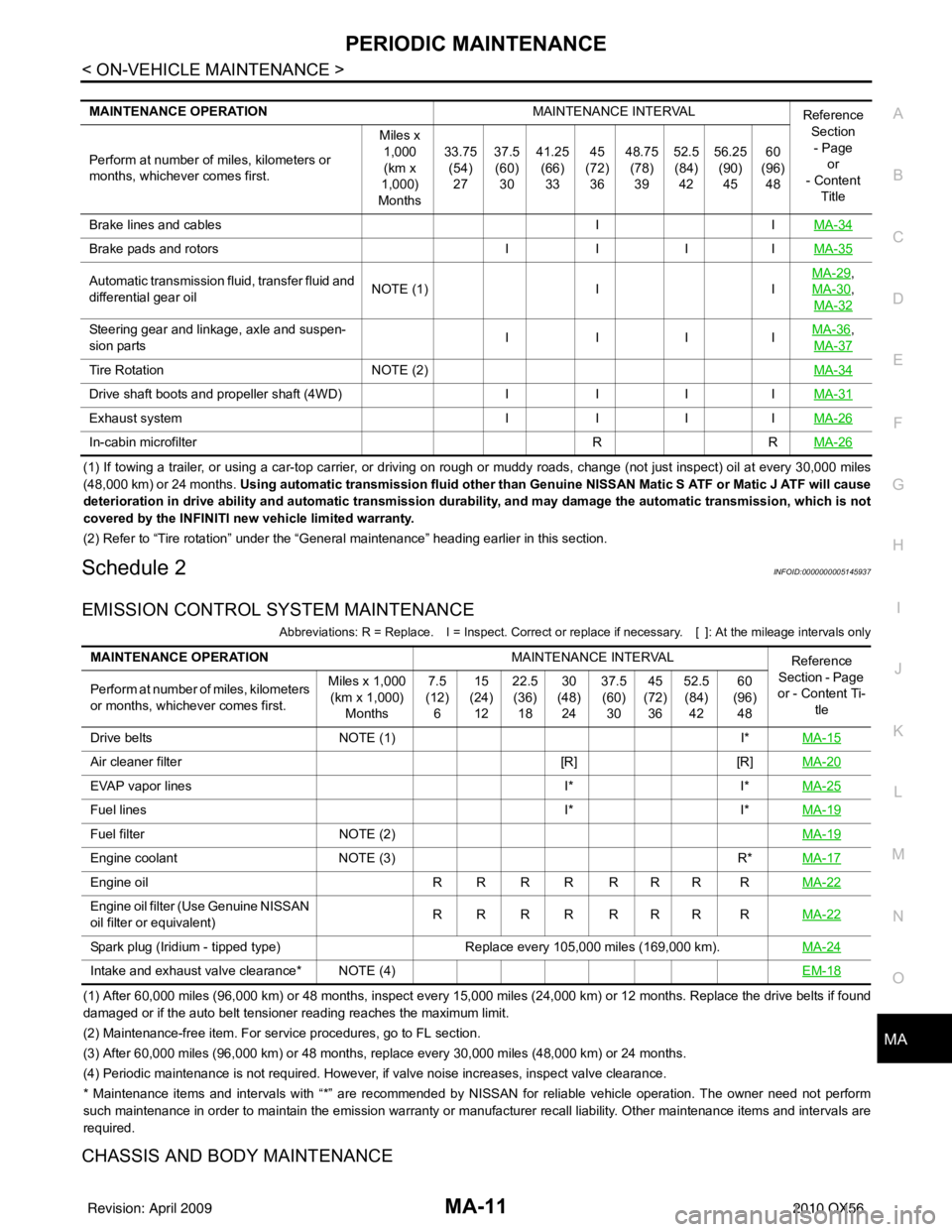
(1) If towing a trailer, or using a car-top carrier, or driving on rough or muddy roads, change (not just inspect) oil at every
30,000 miles
(48,000 km) or 24 months. Using automatic transmission fluid other than Ge nuine NISSAN Matic S ATF or Matic J ATF will cause
deterioration in drive ability and automatic transmission durability, and may damage the automatic transmission, which is not
covered by the INFINITI new vehicle limited warranty.
(2) Refer to “Tire rotation” under the “General maintenance” heading earlier in this section.
Schedule 2INFOID:0000000005145937
EMISSION CONTROL SYSTEM MAINTENANCE
Abbreviations: R = Replace. I = Ins pect. Correct or replace if necessary. [ ]: At the mileage intervals only
(1) After 60,000 miles (96,000 km) or 48 months, inspect every 15,000 miles (24,000 km) or 12 months. Replace the drive belts i f found
damaged or if the auto belt tensioner reading reaches the maximum limit.
(2) Maintenance-free item. For service procedures, go to FL section.
(3) After 60,000 miles (96,000 km) or 48 months, replace every 30,000 miles (48,000 km) or 24 months.
(4) Periodic maintenance is not required. However, if valve noise increases, inspect valve clearance.
* Maintenance items and inte rvals with “*” are recommended by NISSAN for reliable vehicle operation. The owner need not perform
such maintenance in order to maintain the emission warranty or manufacturer recall liability. Other maintenance items and inter vals are
required.
CHASSIS AND BODY MAINTENANCE
MAINTENANCE OPERATION MAINTENANCE INTERVAL
Reference
Section
- Page or
- Content
Title
Perform at number of miles, kilometers or
months, whichever comes first. Miles x
1,000(km x
1,000)
Months 33.75
(54)
27 37.5
(60)
30 41.25
(66)
33 45
(72)
36 48.75
(78)
39 52.5
(84)
42 56.25
(90)
45 60
(96)
48
Brake lines and cables IIMA-34
Brake pads and rotors IIIIMA-35
Automatic transmission fluid, transfer fluid and
differential gear oil NOTE (1)
IIMA-29,
MA-30
,
MA-32
Steering gear and linkage, axle and suspen-
sion parts IIII
MA-36,
MA-37
Tire Rotation NOTE (2) MA-34
Drive shaft boots and propeller shaft (4WD)IIIIMA-31
Exhaust system IIIIMA-26
In-cabin microfilter RRMA-26
MAINTENANCE OPERATION MAINTENANCE INTERVAL
Reference
Section - Page
or - Content Ti- tle
Perform at number of miles, kilometers
or months, whichever comes first. Miles x 1,000
(km x 1,000) Months 7.5
(12) 6 15
(24) 12 22.5
(36) 18 30
(48) 24 37.5
(60) 30 45
(72) 36 52.5
(84) 42 60
(96) 48
Drive belts NOTE (1) I*MA-15
Air cleaner filter [R][R]MA-20
EVAP vapor lines I*I*MA-25
Fuel lines I*I*MA-19
Fuel filter NOTE (2) MA-19
Engine coolantNOTE (3) R*MA-17
Engine oil R R R R R R R R MA-22
Engine oil filter (Use Genuine NISSAN
oil filter or equivalent)RRRR RRR R
MA-22
Spark plug (Iridium - tipped type) Replace every 105,000 miles (169,000 km).MA-24
Intake and exhaust valve clearance* NOTE (4) EM-18
Revision: April 20092010 QX56
Page 2717 of 4210
RECOMMENDED FLUIDS AND LUBRICANTSMA-13
< ON-VEHICLE MAINTENANCE >
C
DE
F
G H
I
J
K L
M B
MA
N
O A
RECOMMENDED FLUIDS AND LUBRICANTS
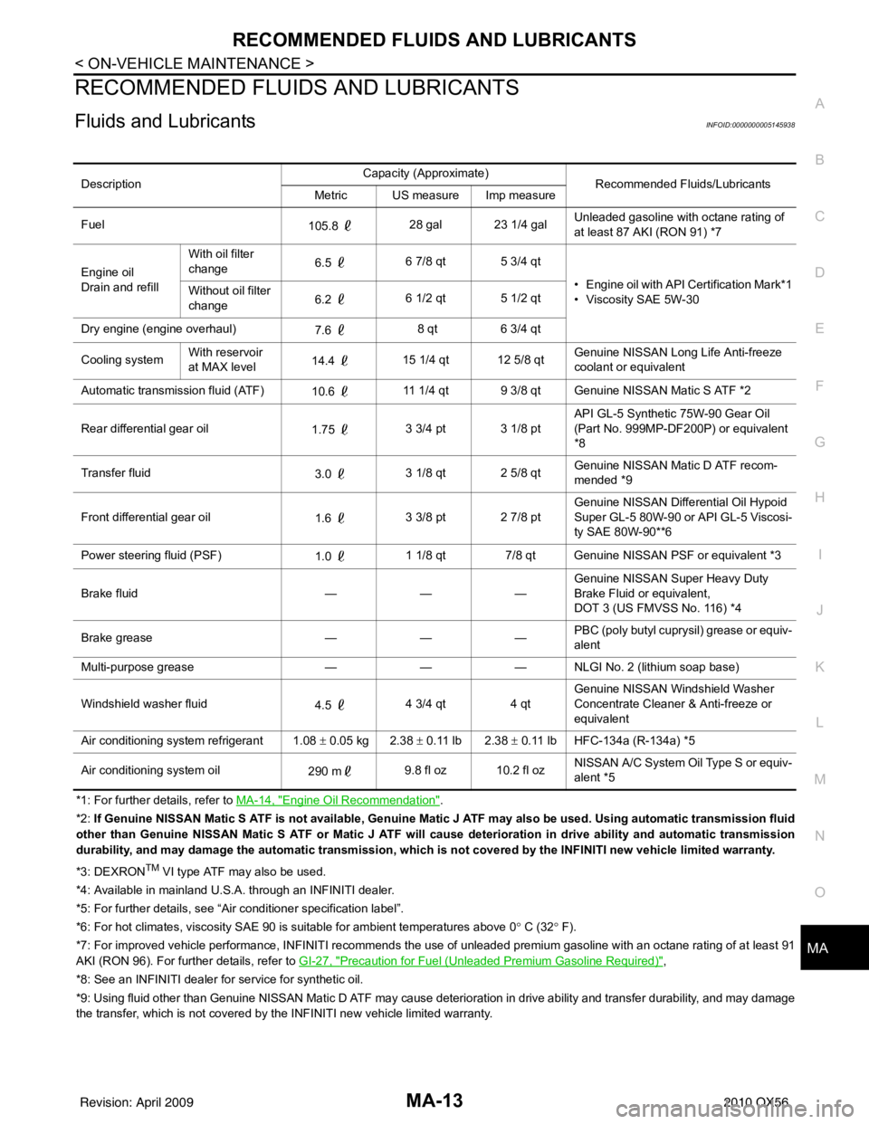
Fluids and LubricantsINFOID:0000000005145938
*1: For further details, refer to
MA-14, "Engine Oil Recommendation".
*2: If Genuine NISSAN Matic S ATF is not ava ilable, Genuine Matic J ATF may also be used. Using automatic transmission fluid
other than Genuine NISSAN Matic S ATF or Matic J ATF will cause deterioration in drive ability and automatic transmission
durability, and may damage the automatic transmission, which is not covered by the INFINITI new vehicle limited warranty.
*3: DEXRON
TM VI type ATF may also be used.
*4: Available in mainland U.S.A. through an INFINITI dealer.
*5: For further details, see “Air conditioner specification label”.
*6: For hot climates, viscosity SAE 90 is suitable for ambient temperatures above 0° C (32° F).
*7: For improved vehicle performance, INFINITI recommends the use of unleaded premium gasoline with an octane rating of at leas t 91
AKI (RON 96). For furt her details, refer to GI-27, "
Precaution for Fuel (Unleaded Premium Gasoline Required)",
*8: See an INFINITI dealer for service for synthetic oil.
*9: Using fluid other than Genuin e NISSAN Matic D ATF may cause deterioration in drive ability and transfer durability, and may damage
the transfer, which is not covered by the INFINITI new vehicle limited warranty. Description
Capacity (Approximate)
Recommended Fluids/Lubricants
Metric US measure Imp measure
Fuel 105.8 28 gal 23 1/4 gal Unleaded gasoline with octane rating of
at least 87 AKI (RON 91) *7
Engine oil
Drain and refill With oil filter
change
6.5
6 7/8 qt 5 3/4 qt
• Engine oil with API Certification Mark*1
• Viscosity SAE 5W-30
Without oil filter
change
6.2
6 1/2 qt 5 1/2 qt
Dry engine (engine overhaul) 7.6 8 qt
6 3/4 qt
Cooling system With reservoir
at MAX level
14.4
15 1/4 qt 12 5/8 qt Genuine NISSAN Long
Life Anti-freeze
coolant or equivalent
Automatic transmission fluid (ATF) 10.6 11 1/4 qt 9 3/8 qt Genuine NISSAN Matic S ATF *2
Rear differential gear oil 1.75 3 3/4 pt 3 1/8 pt API GL-5 Synthetic 75W-90 Gear Oil
(Part No. 999MP-DF200P) or equivalent
*8
Transfer fluid 3.0 3 1/8 qt 2 5/8 qt Genuine NISSAN Matic D ATF recom-
mended *9
Front differential gear oil 1.6 3 3/8 pt 2 7/8 pt Genuine NISSAN Differ
ential Oil Hypoid
Super GL-5 80W-90 or API GL-5 Viscosi-
ty SAE 80W-90**6
Power steering fluid (PSF) 1.0 1 1/8 qt 7/8 qt Genuine NISSAN PSF or equivalent *3
Brake fluid ———Genuine NISSAN S
uper Heavy Duty
Brake Fluid or equivalent,
DOT 3 (US FMVSS No. 116) *4
Brake grease ———PBC (poly butyl cuprysil) grease or equiv-
alent
Multi-purpose grease ——— NLGI No. 2 (lithium soap base)
Windshield washer fluid 4.5 4 3/4 qt
4 qtGenuine NISSAN Wind
shield Washer
Concentrate Cleaner & Anti-freeze or
equivalent
Air conditioning system refrigerant 1.08 ± 0.05 kg 2.38 ± 0.11 lb 2.38 ± 0.11 lb HFC-134a (R-134a) *5
Air conditioning system oil 290 m9.8 fl oz 10.2 fl oz NISSAN A/C System Oil Type S or equiv-
alent *5
Revision: April 20092010 QX56
Page 2721 of 4210
ENGINE MAINTENANCEMA-17
< ON-VEHICLE MAINTENANCE >
C
DE
F
G H
I
J
K L
M B
MA
N
O A
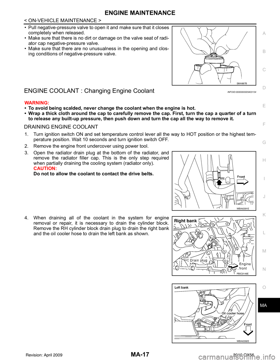
• Pull negative-pressure valve to open it and make sure that it closes
completely when released.
• Make sure that there is no dirt or damage on the valve seat of radi-
ator cap negative-pressure valve.
• Make sure that there are no unusualness in the opening and clos- ing conditions of negative-pressure valve.
ENGINE COOLANT : Chang ing Engine CoolantINFOID:0000000005403134
WARNING:
• To avoid being scalded, never change the coolant when the engine is hot.
• Wrap a thick cloth around the cap to carefully remo ve the cap. First, turn the cap a quarter of a turn
to release any built-up pressure, then push down and turn the cap all the way to remove it.
DRAINING ENGINE COOLANT
1. Turn ignition switch ON and set temperature control lever all the way to HOT position or the highest tem-
perature position. Wait 10 seconds and turn ignition switch OFF.
2. Remove the engine front undercover using power tool.
3. Open the radiator drain plug at the bottom of the radiator, and remove the radiator filler cap. This is the only step required
when partially draining the cooling system (radiator only).
CAUTION:
Do not to allow the coolant to contact the drive belts.
4. When draining all of the coolant in the system for engine removal or repair, it is necessary to drain the cylinder block.
Remove the RH cylinder block drain plug to drain the right bank
and the oil cooler hose to drain the left bank as shown.
SMA967B
WBIA0391E
PBIC0146E
WBIA0392E
Revision: April 20092010 QX56