2010 INFINITI QX56 brake rotor
[x] Cancel search: brake rotorPage 2714 of 4210
MA-10
< ON-VEHICLE MAINTENANCE >
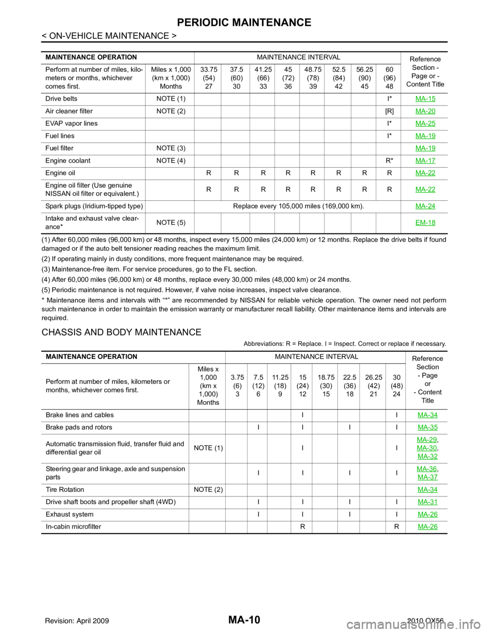
PERIODIC MAINTENANCE
(1) After 60,000 miles (96,000 km) or 48 months, inspect every 15,000 miles (24,000 km) or 12 months. Replace the drive belts if found
damaged or if the auto belt tensioner reading reaches the maximum limit.
(2) If operating mainly in dusty conditions, more frequent maintenance may be required.
(3) Maintenance-free item. For service procedures, go to the FL section.
(4) After 60,000 miles (96,000 km) or 48 months, replace every 30,000 miles (48,000 km) or 24 months.
(5) Periodic maintenance is not required. However, if valve noise increases, inspect valve clearance.
* Maintenance items and intervals with “*” are recommended by NISSAN for reliable vehicle operation. The owner need not perform
such maintenance in order to maintain the emission warranty or manufacturer recall liability. Other maintenance items and intervals are
required.
CHASSIS AND BODY MAINTENANCE
Abbreviations: R = Replace. I = Inspec t. Correct or replace if necessary.
MAINTENANCE OPERATION MAINTENANCE INTERVAL
Reference
Section -
Page or -
Content Title
Perform at number of miles, kilo-
meters or months, whichever
comes first. Miles x 1,000
(km x 1,000) Months 33.75
(54)27 37.5
(60) 30 41.25
(66)33 45
(72) 36 48.75
(78)39 52.5
(84) 42 56.25
(90)45 60
(96) 48
Drive belts NOTE (1) I*MA-15
Air cleaner filter NOTE (2) [R]MA-20
EVAP vapor lines I*MA-25
Fuel lines I*MA-19
Fuel filter NOTE (3) MA-19
Engine coolantNOTE (4) R*MA-17
Engine oil R R R R R R R R MA-22
Engine oil filter (Use genuine
NISSAN oil filter or equivalent.)R R RRRRRR
MA-22
Spark plugs (Iridium-tipped type)Replace every 105,000 miles (169,000 km).MA-24
Intake and exhaust valve clear-
ance*NOTE (5)
EM-18
MAINTENANCE OPERATIONMAINTENANCE INTERVAL
Reference
Section- Page or
- Content Title
Perform at number of miles, kilometers or
months, whichever comes first. Miles x
1,000
(km x
1,000)
Months 3.75
(6)3 7.5
(12) 6 11 . 2 5
(18) 9 15
(24) 12 18.75
(30)15 22.5
(36) 18 26.25
(42)21 30
(48) 24
Brake lines and cables IIMA-34
Brake pads and rotors II I IMA-35
Automatic transmission fluid, transfer fluid and
differential gear oil NOTE (1)
IIMA-29,
MA-30
,
MA-32
Steering gear and linkage, axle and suspension
parts II I I
MA-36,
MA-37
Tire Rotation NOTE (2) MA-34
Drive shaft boots and propeller shaft (4WD)II I IMA-31
Exhaust system II I IMA-26
In-cabin microfilter RRMA-26
Revision: April 20092010 QX56
Page 2715 of 4210
PERIODIC MAINTENANCEMA-11
< ON-VEHICLE MAINTENANCE >
C
DE
F
G H
I
J
K L
M B
MA
N
O A
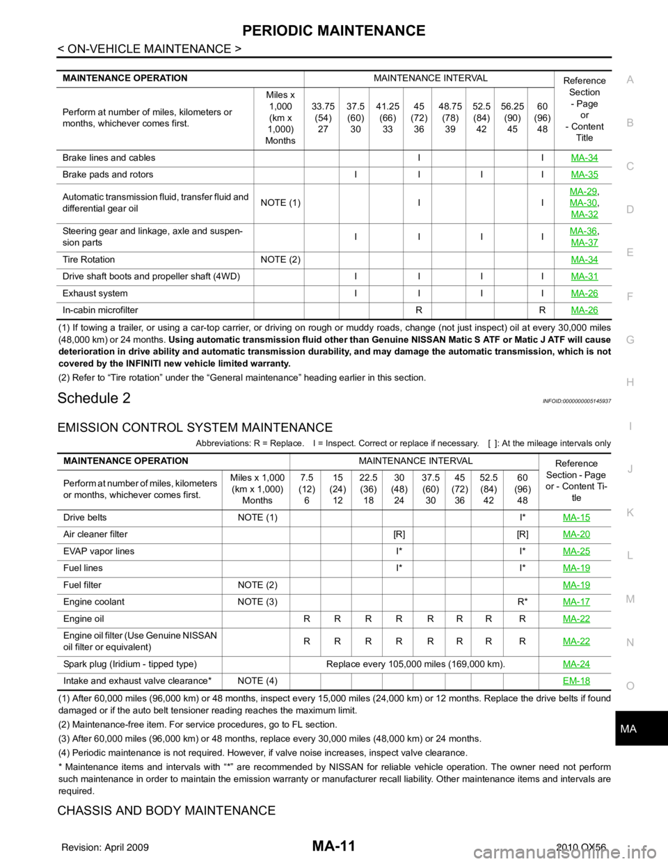
(1) If towing a trailer, or using a car-top carrier, or driving on rough or muddy roads, change (not just inspect) oil at every
30,000 miles
(48,000 km) or 24 months. Using automatic transmission fluid other than Ge nuine NISSAN Matic S ATF or Matic J ATF will cause
deterioration in drive ability and automatic transmission durability, and may damage the automatic transmission, which is not
covered by the INFINITI new vehicle limited warranty.
(2) Refer to “Tire rotation” under the “General maintenance” heading earlier in this section.
Schedule 2INFOID:0000000005145937
EMISSION CONTROL SYSTEM MAINTENANCE
Abbreviations: R = Replace. I = Ins pect. Correct or replace if necessary. [ ]: At the mileage intervals only
(1) After 60,000 miles (96,000 km) or 48 months, inspect every 15,000 miles (24,000 km) or 12 months. Replace the drive belts i f found
damaged or if the auto belt tensioner reading reaches the maximum limit.
(2) Maintenance-free item. For service procedures, go to FL section.
(3) After 60,000 miles (96,000 km) or 48 months, replace every 30,000 miles (48,000 km) or 24 months.
(4) Periodic maintenance is not required. However, if valve noise increases, inspect valve clearance.
* Maintenance items and inte rvals with “*” are recommended by NISSAN for reliable vehicle operation. The owner need not perform
such maintenance in order to maintain the emission warranty or manufacturer recall liability. Other maintenance items and inter vals are
required.
CHASSIS AND BODY MAINTENANCE
MAINTENANCE OPERATION MAINTENANCE INTERVAL
Reference
Section
- Page or
- Content
Title
Perform at number of miles, kilometers or
months, whichever comes first. Miles x
1,000(km x
1,000)
Months 33.75
(54)
27 37.5
(60)
30 41.25
(66)
33 45
(72)
36 48.75
(78)
39 52.5
(84)
42 56.25
(90)
45 60
(96)
48
Brake lines and cables IIMA-34
Brake pads and rotors IIIIMA-35
Automatic transmission fluid, transfer fluid and
differential gear oil NOTE (1)
IIMA-29,
MA-30
,
MA-32
Steering gear and linkage, axle and suspen-
sion parts IIII
MA-36,
MA-37
Tire Rotation NOTE (2) MA-34
Drive shaft boots and propeller shaft (4WD)IIIIMA-31
Exhaust system IIIIMA-26
In-cabin microfilter RRMA-26
MAINTENANCE OPERATION MAINTENANCE INTERVAL
Reference
Section - Page
or - Content Ti- tle
Perform at number of miles, kilometers
or months, whichever comes first. Miles x 1,000
(km x 1,000) Months 7.5
(12) 6 15
(24) 12 22.5
(36) 18 30
(48) 24 37.5
(60) 30 45
(72) 36 52.5
(84) 42 60
(96) 48
Drive belts NOTE (1) I*MA-15
Air cleaner filter [R][R]MA-20
EVAP vapor lines I*I*MA-25
Fuel lines I*I*MA-19
Fuel filter NOTE (2) MA-19
Engine coolantNOTE (3) R*MA-17
Engine oil R R R R R R R R MA-22
Engine oil filter (Use Genuine NISSAN
oil filter or equivalent)RRRR RRR R
MA-22
Spark plug (Iridium - tipped type) Replace every 105,000 miles (169,000 km).MA-24
Intake and exhaust valve clearance* NOTE (4) EM-18
Revision: April 20092010 QX56
Page 2716 of 4210
MA-12
< ON-VEHICLE MAINTENANCE >
PERIODIC MAINTENANCE
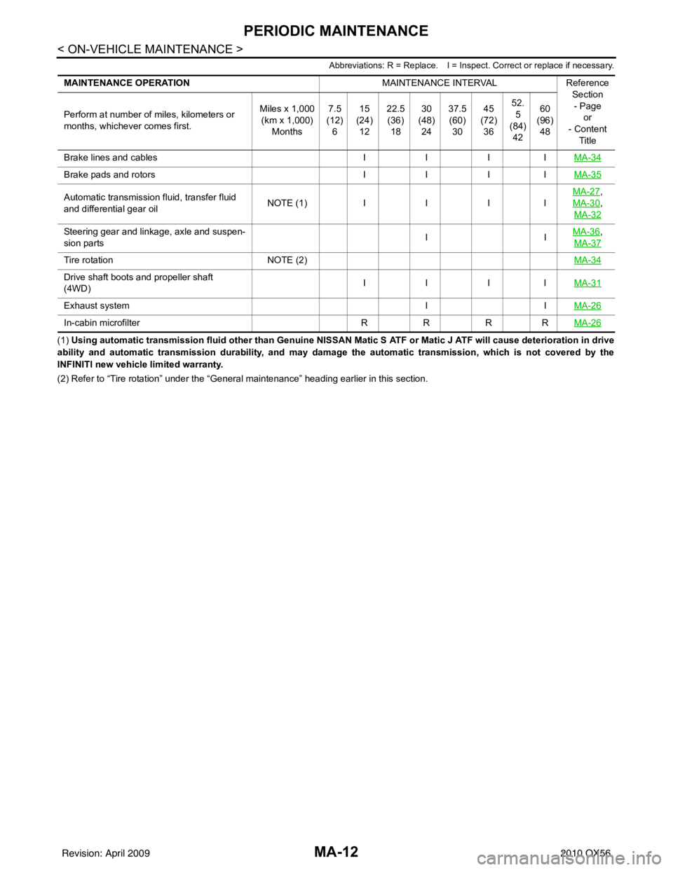
Abbreviations: R = Replace. I = Inspect. Correct or replace if necessary.
(1) Using automatic transmission fluid other than Genuine NISSAN Matic S ATF or Matic J ATF will cause deterioration in drive
ability and automatic transmission durability, and may damage the automatic transmission, which is not covered by the
INFINITI new vehicle limited warranty.
(2) Refer to “Tire rotation” unde r the “General maintenance” heading earlier in this section.
MAINTENANCE OPERATION
MAINTENANCE INTERVALReference
Section
- Page or
- Content
Title
Perform at number of miles, kilometers or
months, whichever comes first.
Miles x 1,000
(km x 1,000)
Months 7.5
(12)
6 15
(24)
12 22.5
(36)
18 30
(48)
24 37.5
(60)
30 45
(72)
36 52.
5
(84) 42 60
(96)
48
Brake lines and cables IIIIMA-34
Brake pads and rotors IIIIMA-35
Automatic transmission fluid, transfer fluid
and differential gear oil N
O TE (1)IIII MA-27,
MA-30
,
MA-32
Steering gear and linkage, axle and suspen-
sion parts IIMA-36,
MA-37
Tire rotation NOTE (2) MA-34
Drive shaft boots and propeller shaft
(4WD)IIII
MA-31
Exhaust system IIMA-26
In-cabin microfilter RRRRMA-26
Revision: April 20092010 QX56
Page 2739 of 4210
CHASSIS AND BODY MAINTENANCEMA-35
< ON-VEHICLE MAINTENANCE >
C
DE
F
G H
I
J
K L
M B
MA
N
O A
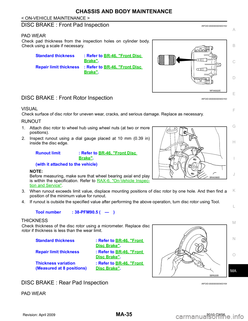
DISC BRAKE : Front Pad InspectionINFOID:0000000005403162
PA D W E A R
Check pad thickness from the inspection holes on cylinder body.
Check using a scale if necessary.
DISC BRAKE : Front Rotor InspectionINFOID:0000000005403163
VISUAL
Check surface of disc rotor for uneven wear, cracks, and serious damage. Replace as necessary.
RUNOUT
1. Attach disc rotor to wheel hub using wheel nuts (at two or more
positions).
2. Inspect runout using a dial gauge placed at 10 mm (0.39 in) inside the disc edge.
NOTE:
Before measuring, make sure that wheel bearing axial end play
is within the specification. Refer to RAX-6, "
On-Vehicle Inspec-
tion and Service".
3. When runout exceeds limit value, displace mounting positions of disc rotor by one hole. And then find a position of the minimum value for runout.
4. If runout is outside the specified value after performing the above operation, turn disc rotor using Tool.
THICKNESS
Check thickness of the disc rotor using a micrometer. Replace disc
rotor if thickness is less than the wear limit.
DISC BRAKE : Rear Pad InspectionINFOID:0000000005403164
PA D W E A R
Standard thickness : Refer to BR-46, "Front Disc
Brake".
Repair limit thickness : Refer to BR-46, "
Front Disc
Brake".
WFIA0522E
Runout limit : Refer to BR-46, "Front Disc
Brake".
(with it attached to the vehicle)
Tool number : 38-PFM90.5 ( — )
BRA0580D
Standard thickness : Refer to BR-46, "Front
Disc Brake".
Repair limit thickness : Refer to BR-46, "
Front
Disc Brake".
Thickness variation
(Measured at 8 positions) : Refer to
BR-46, "
Front
Disc Brake".
SBR020B
Revision: April 20092010 QX56
Page 2740 of 4210
MA-36
< ON-VEHICLE MAINTENANCE >
CHASSIS AND BODY MAINTENANCE
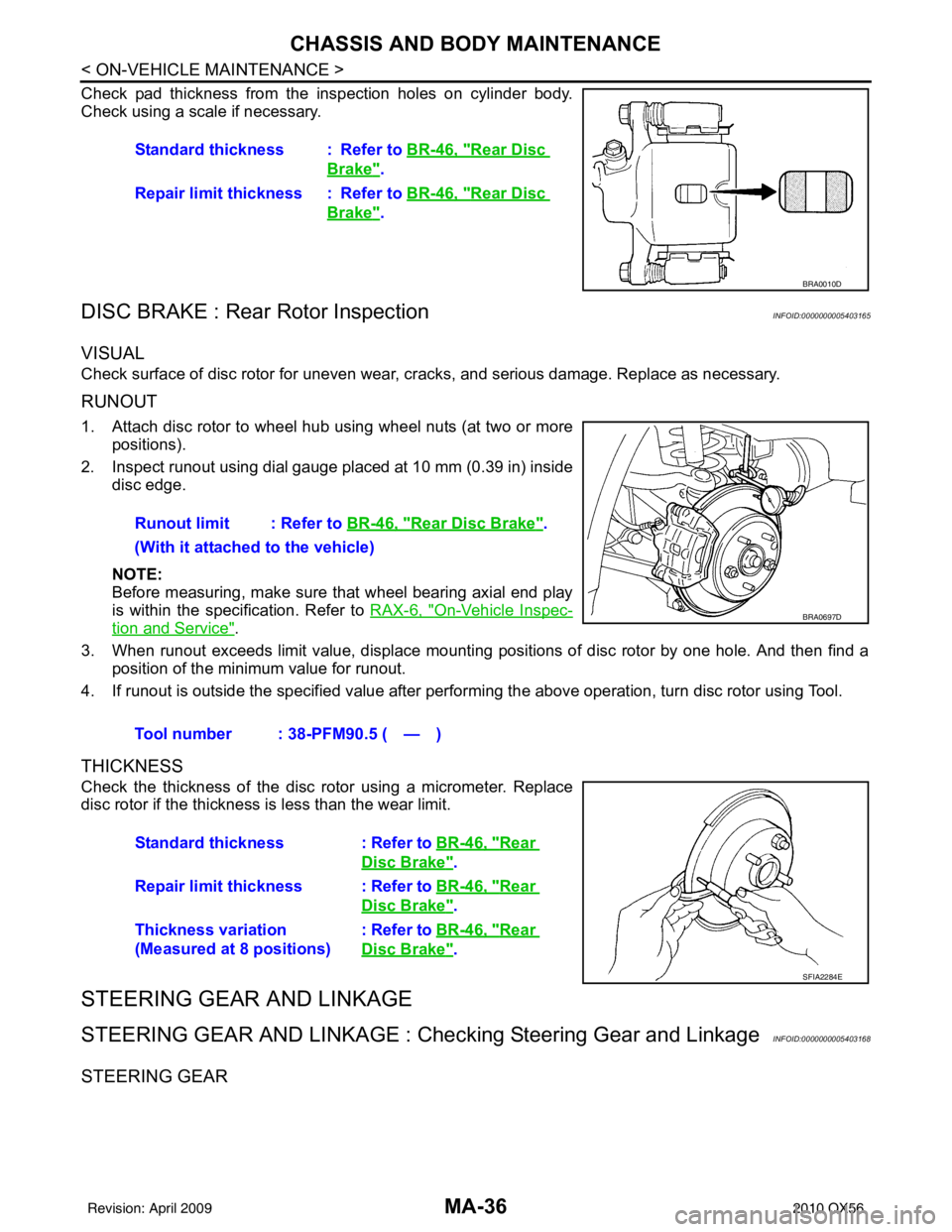
Check pad thickness from the inspection holes on cylinder body.
Check using a scale if necessary.
DISC BRAKE : Rear Rotor InspectionINFOID:0000000005403165
VISUAL
Check surface of disc rotor for uneven wear, cracks, and serious damage. Replace as necessary.
RUNOUT
1. Attach disc rotor to wheel hub using wheel nuts (at two or more
positions).
2. Inspect runout using dial gauge placed at 10 mm (0.39 in) inside disc edge.
NOTE:
Before measuring, make sure that wheel bearing axial end play
is within the specification. Refer to RAX-6, "
On-Vehicle Inspec-
tion and Service".
3. When runout exceeds limit value, displace mounting positions of disc rotor by one hole. And then find a position of the minimum value for runout.
4. If runout is outside the specified value after performing the above operation, turn disc rotor using Tool.
THICKNESS
Check the thickness of the disc rotor using a micrometer. Replace
disc rotor if the thickness is less than the wear limit.
STEERING GEAR AND LINKAGE
STEERING GEAR AND LINKAGE : Che cking Steering Gear and LinkageINFOID:0000000005403168
STEERING GEAR
Standard thickness : Refer to BR-46, "Rear Disc
Brake".
Repair limit thickness : Refer to BR-46, "
Rear Disc
Brake".
BRA0010D
Runout limit : Refer to BR-46, "Rear Disc Brake".
(With it attached to the vehicle)
Tool number : 38-PFM90.5 ( — )
BRA0697D
Standard thickness : Refer to BR-46, "Rear
Disc Brake".
Repair limit thickness : Refer to BR-46, "
Rear
Disc Brake".
Thickness variation
(Measured at 8 positions) : Refer to BR-46, "
Rear
Disc Brake".
SFIA2284E
Revision: April 20092010 QX56
Page 2867 of 4210
PB-4
< PREPARATION >
PREPARATION
PREPARATION
PREPARATION
Commercial Service ToolINFOID:0000000005147931
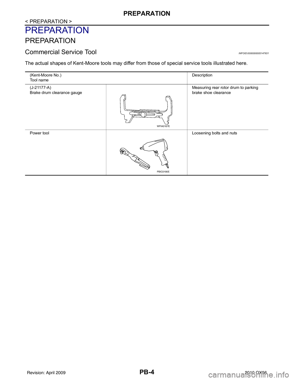
The actual shapes of Kent-Moore tools may differ from those of special service tools illustrated here.
(Kent-Moore No.)
Tool name Description
(J-21177-A)
Brake drum clearance gauge Measuring rear rotor drum to parking
brake shoe clearance
Power tool Loosening bolts and nuts
WFIA0167E
PBIC0190E
Revision: April 20092010 QX56
Page 2868 of 4210
PARKING BRAKE SYSTEMPB-5
< ON-VEHICLE MAINTENANCE >
C
DE
G H
I
J
K L
M A
B
PB
N
O P
ON-VEHICLE MAINTENANCE
PARKING BRAKE SYSTEM
On-Vehicle ServiceINFOID:0000000005147932
PEDAL STROKE
• When parking brake pedal is operated with the specified forc e, make sure the stroke is within the specified
number of notches. Check by listening and counting the ratchet clicks.
INSPECTION
• Make sure the components are attached pr operly, checking for looseness or backlash.
• Check parking brake pedal assembly for bends, damage and cracks, and replace if necessary.
• Check cable for wear and damage, and replace if necessary.
• Check parking brake warning lamp switch for malfunction, and replace if necessary. Refer to BCS-38, "
Diag-
nosis Procedure".
ADJUSTMENT
1. Remove the lower instrument panel LH. Refer to IP-14, "Exploded View".
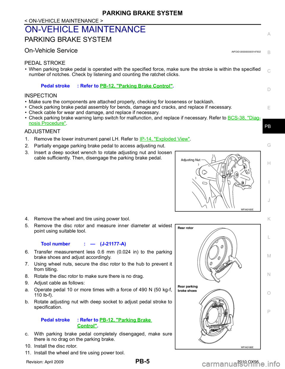
2. Partially engage parking brake pedal to access adjusting nut.
3. Insert a deep socket wrench to rotate adjusting nut and loosen cable sufficiently. Then, disengage the parking brake pedal.
4. Remove the wheel and tire using power tool.
5. Remove the disc rotor and measure inner diameter at widest point using suitable tool.
6. Transfer measurement less 0.6 mm (0.024 in) to the parking brake shoes and adjust accordingly.
7. Using wheel nuts, secure the disc rotor to the hub to prevent it from tilting.
8. Rotate the disc rotor to make sure there is no drag.
9. Adjust cable as follows:
a. Operate pedal 10 or more times with a force of 490 N (50 kg-f, 110 lb-f).
b. Rotate adjusting nut with deep socket to adjust pedal stroke to specification.
c. With parking brake pedal completely disengaged, make sure there is no drag on the parking brake.
10. Install the disc rotor.
11. Install the wheel and tire using power tool. Pedal stroke : Refer to
PB-12, "
Parking Brake Control".
WFIA0165E
Tool number : — (J-21177-A)
Pedal stroke : Refer to PB-12, "
Parking Brake
Control".
WFIA0166E
Revision: April 20092010 QX56
Page 2870 of 4210
PARKING BRAKE CONTROLPB-7
< ON-VEHICLE REPAIR >
C
DE
G H
I
J
K L
M A
B
PB
N
O P
ON-VEHICLE REPAIR
PARKING BRAKE CONTROL
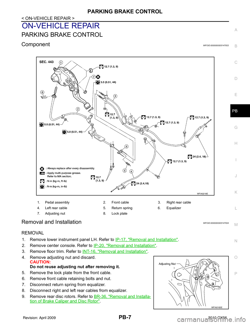
ComponentINFOID:0000000005147933
Removal and InstallationINFOID:0000000005147934
REMOVAL
1. Remove lower instrument panel LH. Refer to IP-17, "Removal and Installation".
2. Remove center console. Refer to IP-20, "
Removal and Installation".
3. Remove floor trim. Refer to INT-16, "
Removal and Installation".
4. Remove adjusting nut and discard. CAUTION:
Do not reuse adjusting nut after removing it.
5. Remove the lock plate from the front cable.
6. Remove front cable retaining bolts and nut.
7. Disconnect return spring from equalizer.
8. Disconnect right and left rear cables from equalizer.
9. Remove rear disc rotors. Refer to BR-36, "
Removal and Installa-
tion of Brake Caliper and Disc Rotor".
1. Pedal assembly 2. Front cable3. Right rear cable
4. Left rear cable 5. Return spring6. Equalizer
7. Adjusting nut 8. Lock plate
WFIA0218E
WFIA0165E
Revision: April 20092010 QX56