Page 2872 of 4210
PARKING BRAKE SHOEPB-9
< ON-VEHICLE REPAIR >
C
DE
G H
I
J
K L
M A
B
PB
N
O P
PARKING BRAKE SHOE
Removal and InstallationINFOID:0000000005147935
COMPONENTS
REMOVAL
WARNING:
Clean the brakes with a vacuum dust co llector to minimize the hazard of airborne particles or other
materials.
NOTE:
Remove the disc rotor only with the parking brake pedal completely in the released position.
1. Remove the rear disc rotor. Refer to BR-36, "
Removal and Installation of Brake Caliper and Disc Rotor".
2. Remove the return springs.
3. Remove the adjuster.
4. Disconnect the rear cable from the toggle lever, if necessary.
• Remove pin retainer and withdraw cable end from toggle lever.
5. Remove the retainers, anti-rattle pins and shoes.
INSPECTION AFTER REMOVAL
Lining Thickness Inspection
1. Anti-rattle pins 2. Back plate3. Shoes
4. Return springs 5. Adjuster6. Retainers
7. Toggle lever
LFIA0222E
Revision: April 20092010 QX56
Page 2873 of 4210

PB-10
< ON-VEHICLE REPAIR >
PARKING BRAKE SHOE
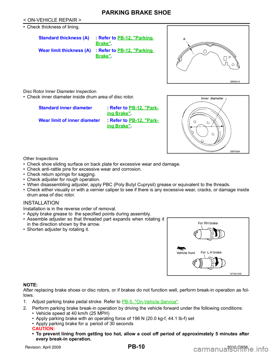
• Check thickness of lining.
Disc Rotor Inner Diameter Inspection
• Check inner diameter insi de drum area of disc rotor.
Other Inspections
• Check shoe sliding surface on back plate for excessive wear and damage.
• Check anti-rattle pins for excessive wear and corrosion.
• Check return springs for sagging.
• Check adjuster for rough operation.
• When disassembling adjuster, apply PBC (Poly Butyl Cuprysil) grease or equivalent to the threads.
• Check either visually or with a vernier caliper to see if there is any excessive wear, cracks, or damage inside
drum area of disc rotor.
INSTALLATION
Installation is in the reverse order of removal.
• Apply brake grease to the specified points during assembly.
• Assemble adjuster so that threaded part expands when rotating it
in the direction shown by the arrow.
• Shorten adjuster by rotating it.
NOTE:
After replacing brake shoes or disc rotors, or if brakes do not function well, perform break-in operation as fol-
lows.
1. Adjust parking brake pedal stroke. Refer to PB-5, "
On-Vehicle Service".
2. Perform parking brake break-in operation by driving the vehicle forward under the following conditions: • Vehicle speed at 40 km/h (25 MPH)
• Apply parking brake with an operating forc e of 196 N (20.0 kg-f, 44.1 lb-f) set
• Apply parking brake for a period of 30 seconds
CAUTION:
• To prevent lining from getting too hot, allow a cool off period of approximately 5 minutes after every break-in operation.Standard thickness (A) : Refer to
PB-12, "
Parking
Brake".
Wear limit thickness (A) : Refer to PB-12, "
Parking
Brake".
SBR021A
Standard inner diameter : Refer to PB-12, "Park-
ing Brake".
Wear limit of inner diameter : Refer to PB-12, "
Park-
ing Brake".
SBR768A
SFIA0153E
Revision: April 20092010 QX56
Page 2875 of 4210
PB-12
< SERVICE DATA AND SPECIFICATIONS (SDS)
SERVICE DATA AND SPECIFICATIONS (SDS)
SERVICE DATA AND SPECIFICATIONS (SDS)
SERVICE DATA AND SPECIFICATIONS (SDS)
Parking BrakeINFOID:0000000005147936
Unit: mm (in)
Parking Brake ControlINFOID:0000000005147937
Typ eDisc rotor with inner drum
Brake lining Standard thickness (new)
3.79 ± 0.21 (0.149 ± 0.008)
Wear limit thickness 0.5 (0.020)
Drum inner diameter (disc) Standard inner diameter (new)
205 ± 0.13 (8.07 ± 0.01)
Wear limit of inner diameter 205.7 (8.10)
Control type Foot pedal
Number of notches [under force of 196 N (20.0 kg-f, 44.1 lb-f)] 3 – 4 notches
Number of notches when warning lamp switch comes on 1 notch
Revision: April 20092010 QX56
Page 3120 of 4210

RAX-8
< REMOVAL AND INSTALLATION >
WHEEL HUB
REMOVAL AND INSTALLATION
WHEEL HUB
Removal and InstallationINFOID:0000000005148956
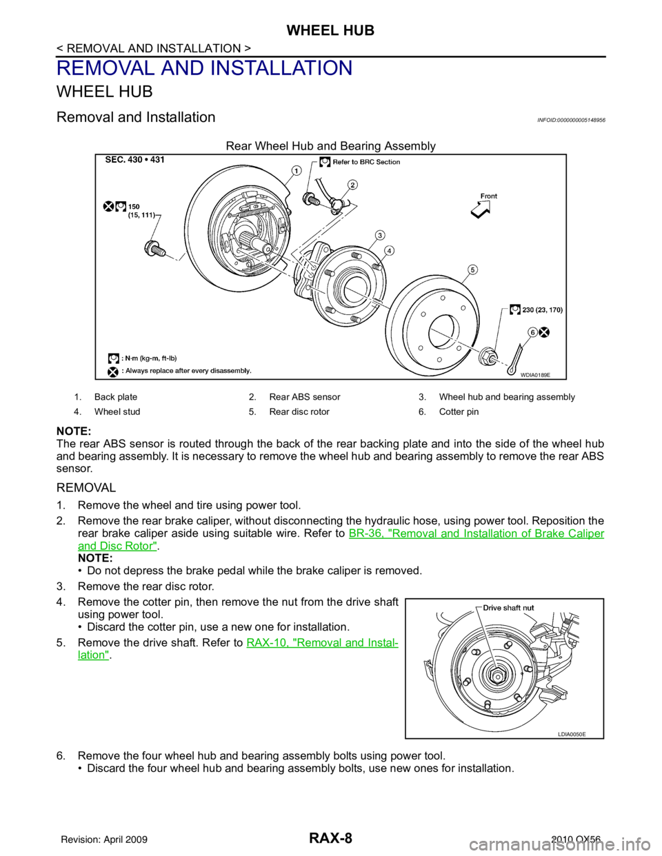
Rear Wheel Hub and Bearing Assembly
NOTE:
The rear ABS sensor is routed through the back of the rear backing plate and into the side of the wheel hub
and bearing assembly. It is necessary to remove the wheel hub and bearing assembly to remove the rear ABS
sensor.
REMOVAL
1. Remove the wheel and tire using power tool.
2. Remove the rear brake caliper, without disconnecting the hydraulic hose, using power tool. Reposition the
rear brake caliper aside using suitable wire. Refer to BR-36, "
Removal and Installation of Brake Caliper
and Disc Rotor".
NOTE:
• Do not depress the brake pedal while the brake caliper is removed.
3. Remove the rear disc rotor.
4. Remove the cotter pin, then remove the nut from the drive shaft using power tool.
• Discard the cotter pin, use a new one for installation.
5. Remove the drive shaft. Refer to RAX-10, "
Removal and Instal-
lation".
6. Remove the four wheel hub and bearing assembly bolts using power tool. • Discard the four wheel hub and bearing assembly bolts, use new ones for installation.
WDIA0189E
1. Back plate 2. Rear ABS sensor3. Wheel hub and be aring assembly
4. Wheel stud 5. Rear disc rotor6. Cotter pin
LDIA0050E
Revision: April 20092010 QX56
Page 3199 of 4210

RSU-12
< REMOVAL AND INSTALLATION >
REAR SUSPENSION MEMBER
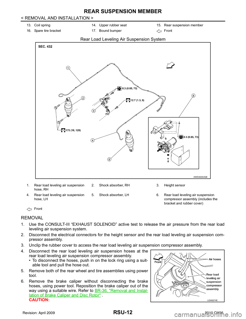
Rear Load Leveling Air Suspension System
REMOVAL
1. Use the CONSULT-III “EXHAUST SOLENOID” active test to release the air pressure from the rear load
leveling air suspension system.
2. Disconnect the electrical connectors for the height sensor and the rear load leveling air suspension com-
pressor assembly.
3. Unclip the rubber cover to access the rear load leveling air suspension compressor assembly.
4. Disconnect the rear load leveling air suspension hoses at the rear load leveling air suspension compressor assembly.
• To disconnect the hoses, push in on the lock ring using a suit-able tool and pull the hose out.
5. Remove both of the rear wheel and tire assemblies using power tool.
6. Remove the brake caliper without disconnecting the brake hoses, using power tool. Reposition the brake caliper out of the
way using a suitable wire. Refer to BR-36, "
Removal and Instal-
lation of Brake Caliper and Disc Rotor" .
CAUTION:
13. Coil spring 14. Upper rubber seat15. Rear suspension member
16. Spare tire bracket 17. Bound bumper Front
AWEIA0054GB
1. Rear load leveling air suspension
hose, RH 2. Shock absorber, RH
3. Height sensor
4. Rear load leveling air suspension hose, LH 5. Shock absorber, LH
6. Rear load leveling air suspension
compressor assembly (includes the
bracket and rubber cover)
Front
LEIA0074E
Revision: April 20092010 QX56