2010 INFINITI QX56 drain bolt
[x] Cancel search: drain boltPage 2734 of 4210
MA-30
< ON-VEHICLE MAINTENANCE >
CHASSIS AND BODY MAINTENANCE
TRANSFER FLUID
TRANSFER FLUID : ReplacementINFOID:0000000005403153
CAUTION:
If using the vehicle for towing, the transfer fluid must be replaced as specified. Refer to MA-9, "
Intro-
duction of Periodic Maintenance".
DRAINING
1. Stop engine.
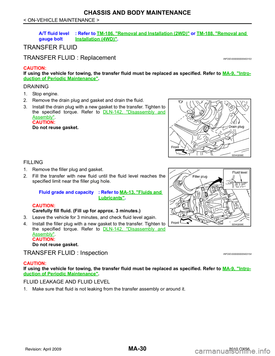
2. Remove the drain plug and gasket and drain the fluid.
3. Install the drain plug with a new gasket to the transfer. Tighten to
the specified torque. Refer to DLN-142, "
Disassembly and
Assembly".
CAUTION:
Do not reuse gasket.
FILLING
1. Remove the filler plug and gasket.
2. Fill the transfer with new fluid until the fluid level reaches the specified limit near the filler plug hole.
CAUTION:
Carefully fill fluid. (Fil l up for approx. 3 minutes.)
3. Leave the vehicle for 3 minutes, and check fluid level again.
4. Install the filler plug with a new gasket to the transfer. Tighten to the specified torque. Refer to DLN-142, "
Disassembly and
Assembly".
CAUTION:
Do not reuse gasket.
TRANSFER FLUID : InspectionINFOID:0000000005403154
CAUTION:
If using the vehicle for towing, the transfer fluid must be replaced as specified. Refer to MA-9, "
Intro-
duction of Periodic Maintenance".
FLUID LEAKAGE AND FLUID LEVEL
1. Make sure that fluid is not leaking from the transfer assembly or around it.A/T fluid level
gauge bolt
: Refer to
TM-186, "
Removal and Installation (2WD)" or TM-188, "Removal and
Installation (4WD)".
SDIA3208E
Fluid grade and capacity : Refer to MA-13, "Fluids and
Lubricants".
SDIA3209E
Revision: April 20092010 QX56
Page 3185 of 4210
SUNROOF SYSTEMRF-57
< ON-VEHICLE REPAIR >
C
DE
F
G H
I
J
L
M A
B
RF
N
O P
CAUTION:
• Before removal, fully close the glass lid assembly. Then, after removal, do not move the motor
assembly.
• After installing or adjusting the sunroof and glass lid, check gap alignment and sunroof operation to
prevent malfunction.
• Handle glass lid with care so not to cause damage.
Removal and InstallationINFOID:0000000005147309
CAUTION:
• Always work with a helper.
• When taking sunroof unit out, use shop cloths to protect the seats and trim from damage.
• After installing the sunroof unit or glass lid, be sure to check gap adjustment to prevent any mal-
function.
SUNROOF FRAME ASSEMBLY
NOTE:
• For easier installation, mark each point before removal.
Removal
1. Remove headlining. Refer to INT-17, "Removal and Installation".
2. Remove the glass lid assembly. Follow the procedure for GLASS LID ASSEMBLY within this section.
3. Remove overhead console bracket.
4. Disconnect the front and rear drain hoses.
5. Remove front sunroof frame assembly bolts.
6. Remove sunroof frame assembly brackets.
7. Remove the side bolts and the sunroof frame assembly.
8. Remove the sunshade assembly as necessary. Fo llow the procedure for SUNSHADE ASSEMBLY within
this section.
Installation
1. Install the sunshade assembly.
2. Position the sunroof frame assembly and install the side bolts.
3. Install the sunroof brackets.
4. Install the front sunroof frame assembly bolts.
5. Connect front and rear drain hoses.
6. Install the overhead console bracket.
7. Install the glass lid assembly. Follow the procedure for GLASS LID ASSEMBLY within this section.
8. Install headlining. Refer to INT-17, "
Removal and Installation".
9. Perform initialization procedure. Refer to RF-5, "
ADDITIONAL SERVICE WHEN REPLACING CONTROL
UNIT : Special Repair Requirement".
GLASS LID ASSEMBLY
Removal
1. Open sunshade assembly.
2. Ensure glass lid assembly is closed.
3. Remove side cover LH and RH.
Revision: April 20092010 QX56
Page 3662 of 4210
ST-24
< REMOVAL AND INSTALLATION >
POWER STEERING GEAR AND LINKAGE
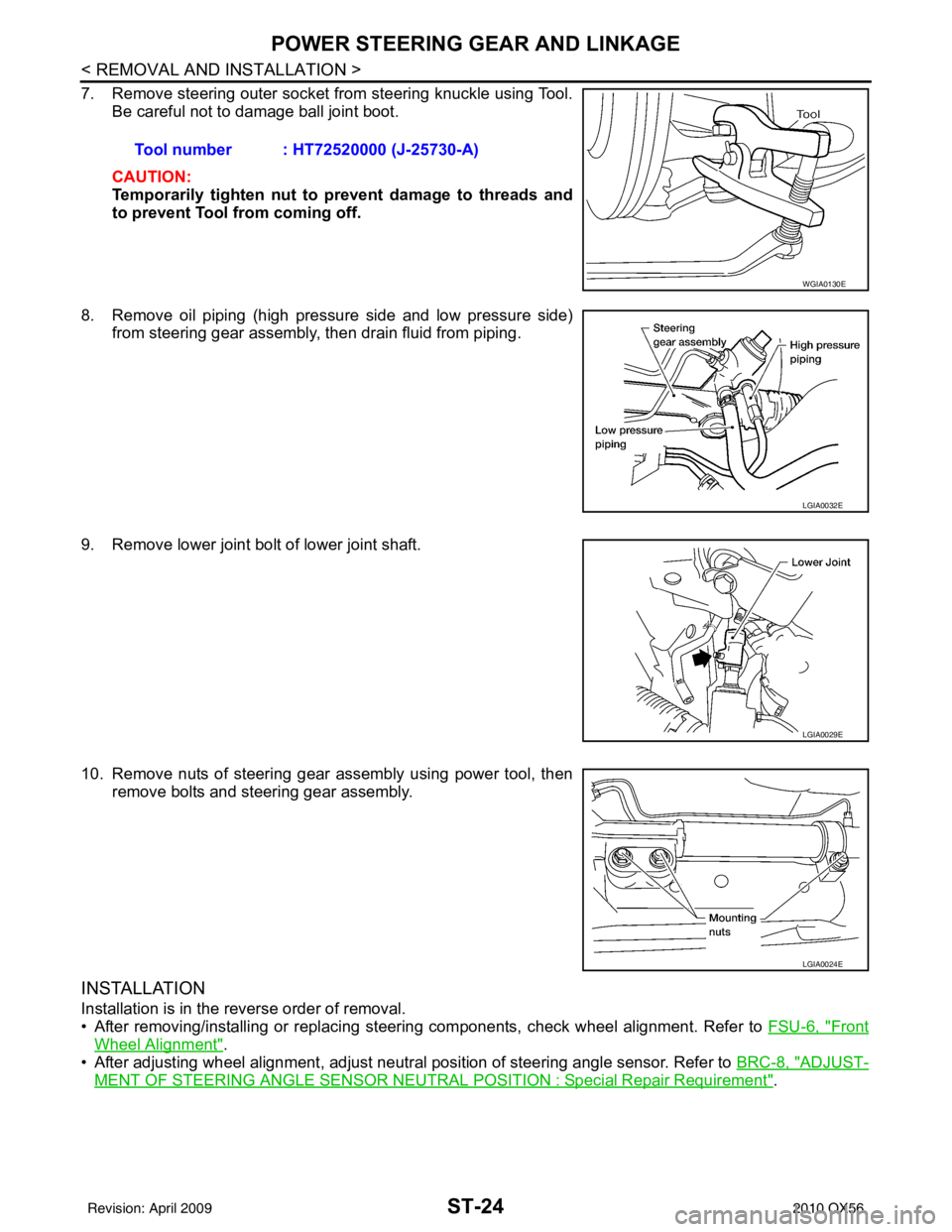
7. Remove steering outer socket from steering knuckle using Tool.Be careful not to damage ball joint boot.
CAUTION:
Temporarily tighten nut to prevent damage to threads and
to prevent Tool from coming off.
8. Remove oil piping (high pressure side and low pressure side) from steering gear assembly, then drain fluid from piping.
9. Remove lower joint bolt of lower joint shaft.
10. Remove nuts of steering gear assembly using power tool, then remove bolts and steering gear assembly.
INSTALLATION
Installation is in the reverse order of removal.
• After removing/installing or replacing steering components, check wheel alignment. Refer to FSU-6, "
Front
Wheel Alignment".
• After adjusting wheel alignment, adjust neutral position of steering angle sensor. Refer to BRC-8, "
ADJUST-
MENT OF STEERING ANGLE SENSOR NEUTRAL POSITION : Special Repair Requirement".
Tool number : HT72520000 (J-25730-A)
WGIA0130E
LGIA0032E
LGIA0029E
LGIA0024E
Revision: April 20092010 QX56
Page 3664 of 4210
ST-26
< REMOVAL AND INSTALLATION >
POWER STEERING OIL PUMP
POWER STEERING OIL PUMP
Removal and InstallationINFOID:0000000005147874
REMOVAL
1. Drain power steering fluid from reservoir tank.
2. Remove engine room cover. Refer to EM-24, "
Removal and Installation".
3. Remove air duct assembly. Refer to EM-25, "
Removal and Installation".
4. Remove power steering reservoir tank.
5. Remove serpentine drive belt belt from auto tensioner and power steering pump. Refer to EM-13,
"Removal and Installation".
6. Disconnect pressure sensor electrical connector.
7. Remove high pressure and low pressure piping from power steering oil pump. Refer to ST-27
.
8. Remove bolts, then remove power steering pump.
INSTALLATION
Installation is in the reverse order of removal. Refer to ST-27 for tightening torque.
• After installation, bleed air. Refer to ST-13, "
Air Bleeding Hydraulic System".
NOTE:
Belt tension is automatic and requires no adjustment.
Revision: April 20092010 QX56
Page 3845 of 4210
TM-150
< ON-VEHICLE MAINTENANCE >
A/T FLUID
Changing the A/T Fluid (ATF)
INFOID:0000000005148723
CAUTION:
If using the vehicle for towing, the A/T fl uid must be replaced as specified. Refer to MA-9, "
Introduc-
tion of Periodic Maintenance".
1. Drive the vehicle to warm up the A/T fluid to approximately 80 ° C (176 ° F).
2. Stop the engine.
3. Remove the A/T fluid level gauge.
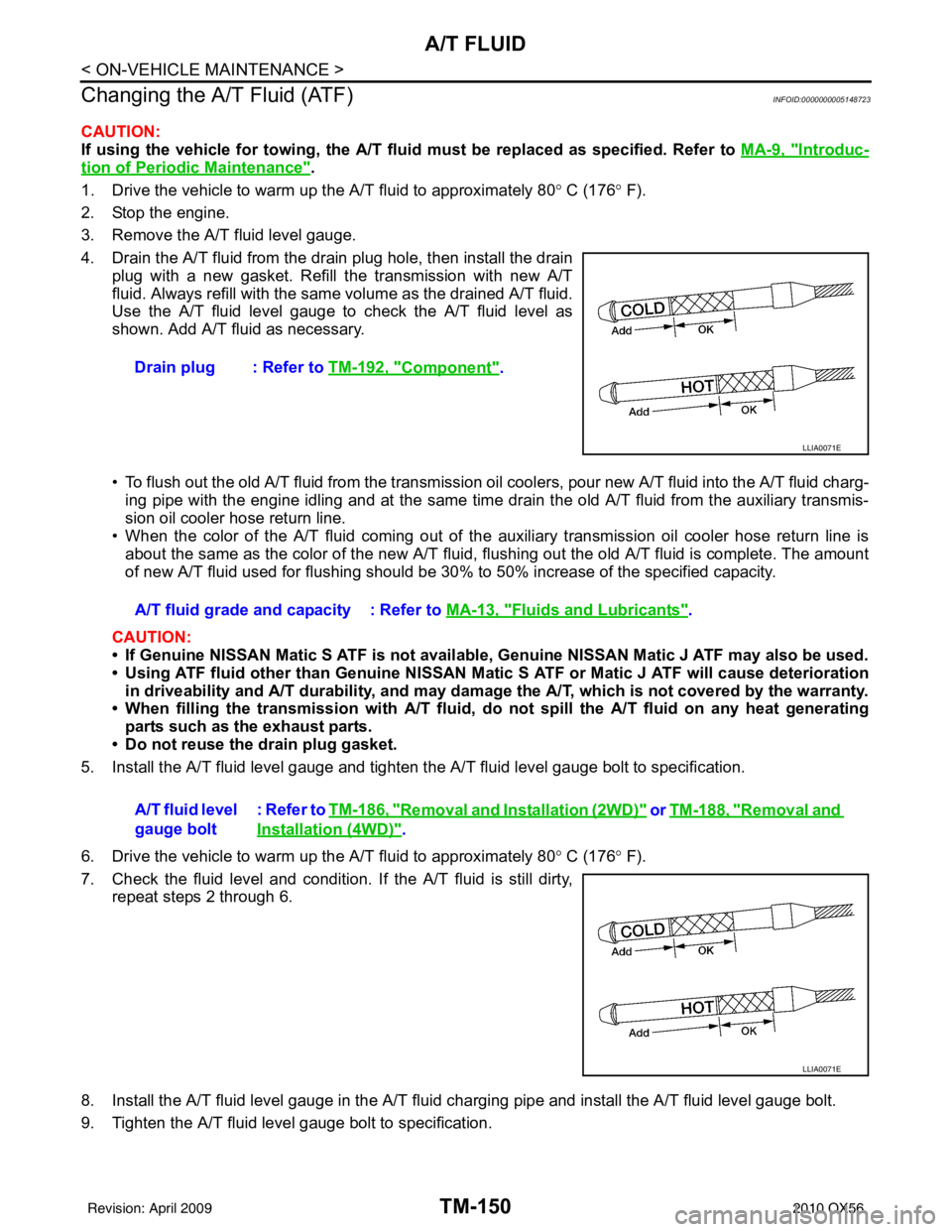
4. Drain the A/T fluid from the drain plug hole, then install the drain plug with a new gasket. Refill the transmission with new A/T
fluid. Always refill with the same volume as the drained A/T fluid.
Use the A/T fluid level gauge to check the A/T fluid level as
shown. Add A/T fluid as necessary.
• To flush out the old A/T fluid from the transmission oil coolers, pour new A/T fluid into the A/T fluid charg-
ing pipe with the engine idling and at the same time drain the old A/T fluid from the auxiliary transmis-
sion oil cooler hose return line.
• When the color of the A/T fluid coming out of the auxiliary transmission oil cooler hose return line is
about the same as the color of the new A/T fluid, flushing out the old A/T fluid is complete. The amount
of new A/T fluid used for flushing should be 30% to 50% increase of the specified capacity.
CAUTION:
• If Genuine NISSAN Matic S ATF is not available, Genuine NISSAN Matic J ATF may also be used.
• Using ATF fluid other than Genuine NISSAN Matic S ATF or Matic J ATF will cause deterioration in driveability and A/T durability, and may damage the A/T, which is not covered by the warranty.
• When filling the transmission with A/T fluid, do not spill the A/T fluid on any heat generating
parts such as the exhaust parts.
• Do not reuse the drain plug gasket.
5. Install the A/T fluid level gauge and tighten the A/T fluid level gauge bolt to specification.
6. Drive the vehicle to warm up the A/T fluid to approximately 80 ° C (176 ° F).
7. Check the fluid level and condition. If the A/T fluid is still dirty, repeat steps 2 through 6.
8. Install the A/T fluid level gauge in the A/T fluid charging pipe and install the A/T fluid level gauge bolt.
9. Tighten the A/T fluid level gauge bolt to specification. Drain plug : Refer to
TM-192, "
Component".
LLIA0071E
A/T fluid grade and capacity : Refer to MA-13, "Fluids and Lubricants".
A/T fluid level
gauge bolt : Refer to TM-186, "
Removal and Installation (2WD)" or TM-188, "Removal and
Installation (4WD)".
LLIA0071E
Revision: April 20092010 QX56
Page 3847 of 4210
TM-152
< ON-VEHICLE MAINTENANCE >
A/T FLUID COOLER
A/T FLUID COOLER
A/T Fluid Cooler CleaningINFOID:0000000005148724
Whenever an A/T is repaired, overhauled, or replaced, the A/T fluid cooler mounted in the radiator must be
inspected and cleaned.
Metal debris and friction material, if present, can become trapped in the A/T fluid cooler. This debris can con-
taminate the newly serviced A/T or, in severe cases, can bloc k or restrict the flow of A/T fluid. In either case,
malfunction of the newly serviced A/T may result.
Debris, if present, may build up as A/T fluid enters the c ooler inlet. It will be necessary to back flush the cooler
through the cooler outlet in order to flush out any built up debris.
A/T FLUID COOLER CLEANING PROCEDURE
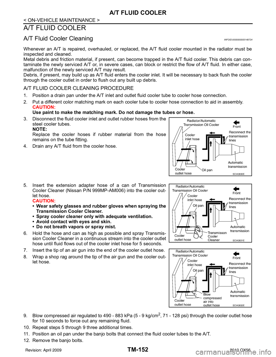
1. Position a drain pan under the A/T inlet and outlet fluid cooler tube to cooler hose connection.
2. Put a different color matching mark on each cooler tube to cooler hose connection to aid in assembly. CAUTION:
Use paint to make the matching mark. Do not damage the tubes or hose.
3. Disconnect the fluid cooler inlet and outlet rubber hoses from the steel cooler tubes.
NOTE:
Replace the cooler hoses if rubber material from the hose
remains on the tube fitting.
4. Drain any A/T fluid from the cooler hose.
5. Insert the extension adapter hose of a can of Transmission
Cooler Cleaner (Nissan P/N 999MP-AM006) into the cooler out-
let hose.
CAUTION:
• Wear safety glasses and rubber gloves when spraying the Transmission Cooler Cleaner.
• Spray cooler cleaner only wi th adequate ventilation.
• Avoid contact with eyes and skin.
• Do not breath vapors or spray mist.
6. Hold the hose and can as high as possible and spray Transmis- sion Cooler Cleaner in a continuous stream into the cooler outlet
hose until fluid flows out of the cooler inlet hose for 5 seconds.
7. Insert the tip of an air gun into the end of the cooler outlet hose.
8. Wrap a shop rag around the tip of the air gun and the cooler out- let hose.
9. Blow compressed air regulated to 490 - 883 kPa (5 - 9 kg/cm
2, 71 - 128 psi) through the cooler outlet hose
for 10 seconds to force out any remaining fluid.
10. Repeat steps 5 through 9 three additional times.
11. Position an oil pan under the banjo bolts that connect the fluid cooler tubes to the A/T.
12. Remove the banjo bolts.
SCIA3830E
SCIA3831E
SCIA3832E
Revision: April 20092010 QX56
Page 3848 of 4210

A/T FLUID COOLERTM-153
< ON-VEHICLE MAINTENANCE >
CEF
G H
I
J
K L
M A
B
TM
N
O P
13. Flush each steel line from the cooler side back toward the A/T by spraying Transmission Cooler Cleaner in a continuous stream for 5 seconds.
14. Blow compressed air regulated to 490 - 883 kPa (5 - 9 kg/cm
2, 71 - 128 psi) through each steel line from
the cooler side back toward the A/T for 10 seconds to force out any remaining fluid.
15. Ensure all debris is removed from the steel cooler lines.
16. Ensure all debris is removed from the banjo bolts and fittings.
17. Perform A/T fluid cooler diagnosis procedure.
A/T FLUID COOLER DIAGNOSIS PROCEDURE
NOTE:
Insufficient cleaning of the cooler inlet hose exte rior may lead to inaccurate debris identification.
1. Position a drain pan under the A/T inlet and outlet fluid cooler tube to cooler hose connection.
2. Clean the exterior and tip of the cooler inlet hose.
3. Put a different color matching mark on each cooler tube to cooler hose connection to aid in assembly. CAUTION:
Use paint to make the matching mark. Do not damage the tubes or hose.
4. Disconnect the fluid cooler inle t and outlet rubber hoses from the
steel cooler tubes.
NOTE:
Replace the cooler hoses if rubber material from the hose
remains on the tube fitting.
5. Insert the extension adapter hose of a can of Transmission Cooler Cleaner (Nissan P/N 999MP-AM006) into the cooler out-
let hose.
CAUTION:
• Wear safety glasses and rubber gloves when spraying the
Transmission Cooler Cleaner.
• Spray cooler cleaner only with adequate ventilation.
• Avoid contact with eyes and skin.
• Do not breath vapors or spray mist.
6. Hold the hose and can as high as possible and spray Transmis- sion Cooler Cleaner in a continuous stream into the cooler outlet
hose until fluid flows out of the cooler inlet hose for 5 seconds.
7. Tie a common white, basket-type coffee filter to the end of the cooler inlet hose.
SCIA3830E
SCIA3831E
SCIA3833E
Revision: April 20092010 QX56
Page 3865 of 4210
TM-170
< ON-VEHICLE REPAIR >
OIL PAN
OIL PAN
Oil PanINFOID:0000000005148740
REMOVAL AND INSTALLATION
Removal
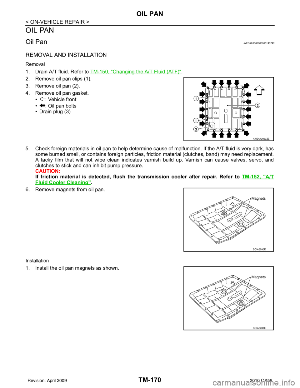
1. Drain A/T fluid. Refer to TM-150, "Changing the A/T Fluid (ATF)".
2. Remove oil pan clips (1).
3. Remove oil pan (2).
4. Remove oil pan gasket. • : Vehicle front
• : Oil pan bolts
• Drain plug (3)
5. Check foreign materials in oil pan to help determine c ause of malfunction. If the A/T fluid is very dark, has
some burned smell, or contains foreign particles, friction material (clutches, band) may need replacement.
A tacky film that will not wipe clean indicates varnish build up. Varnish can cause valves, servo, and
clutches to stick and can inhibit pump pressure.
CAUTION:
If friction material is detected, flush the transmission cooler after repair. Refer to TM-152, "
A/T
Fluid Cooler Cleaning".
6. Remove magnets from oil pan.
Installation
1. Install the oil pan magnets as shown.
AWDIA0023ZZ
SCIA5200E
SCIA5200E
Revision: April 20092010 QX56