Page 3121 of 4210
WHEEL HUBRAX-9
< REMOVAL AND INSTALLATION >
CEF
G H
I
J
K L
M A
B
RAX
N
O P
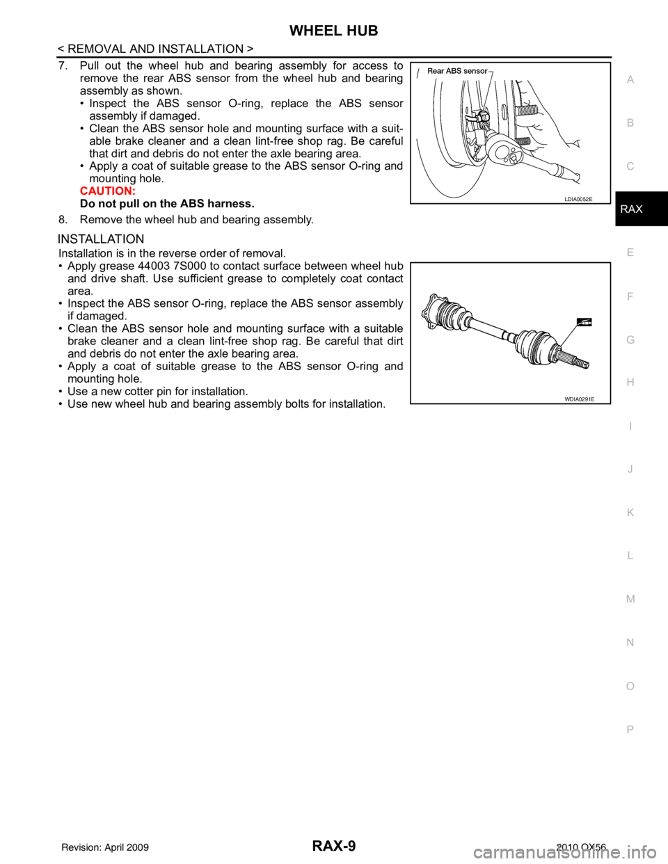
7. Pull out the wheel hub and bearing assembly for access to remove the rear ABS sensor from the wheel hub and bearing
assembly as shown.
• Inspect the ABS sensor O-ri ng, replace the ABS sensor
assembly if damaged.
• Clean the ABS sensor hole and mounting surface with a suit-
able brake cleaner and a clean lint-free shop rag. Be careful
that dirt and debris do not enter the axle bearing area.
• Apply a coat of suitable grease to the ABS sensor O-ring and
mounting hole.
CAUTION:
Do not pull on the ABS harness.
8. Remove the wheel hub and bearing assembly.
INSTALLATION
Installation is in the reverse order of removal.
• Apply grease 44003 7S000 to contact surface between wheel hub and drive shaft. Use sufficient grease to completely coat contact
area.
• Inspect the ABS sensor O-ring, replace the ABS sensor assembly
if damaged.
• Clean the ABS sensor hole and mounting surface with a suitable brake cleaner and a clean lint-free shop rag. Be careful that dirt
and debris do not enter the axle bearing area.
• Apply a coat of suitable grease to the ABS sensor O-ring and mounting hole.
• Use a new cotter pin for installation.
• Use new wheel hub and bearing assembly bolts for installation.
LDIA0052E
WDIA0291E
Revision: April 20092010 QX56
Page 3188 of 4210
RSU-1
SUSPENSION
C
DF
G H
I
J
K L
M
SECTION RSU
A
B
RSU
N
O PCONTENTS
REAR SUSPENSION
PRECAUTION ....... ........................................2
PRECAUTIONS .............................................. .....2
Precaution for Supplemental Restraint System
(SRS) "AIR BAG" and "SEAT BELT PRE-TEN-
SIONER" ............................................................. ......
2
Precaution Necessary for Steering Wheel Rota-
tion After Battery Disconnect ............................... ......
2
Precaution for Rear Suspension ......................... ......3
PREPARATION ............................................4
PREPARATION .............................................. .....4
Commercial Service Tool .................................... ......4
SYMPTOM DIAGNOSIS ...............................5
NOISE, VIBRATION AND HARSHNESS
(NVH) TROUBLESHOOTING ........................ .....
5
NVH Troubleshooting Chart ................................ ......5
ON-VEHICLE MAINTENANCE .....................6
REAR SUSPENSION ASSEMBLY ................ .....6
On-Vehicle Inspection and Service ..................... ......6
Wheel Alignment Inspection ......................................6
ON-VEHICLE REPAIR ..................................9
REAR SUSPENSION ASSEMBLY ................ .....9
Component .......................................................... ......9
REMOVAL AND INSTALLATION ...............11
REAR SUSPENSION MEMBER .................... ....11
Removal and Installation .........................................11
SHOCK ABSORBER ........................................15
Removal and Installation ..................................... ....15
Disposal ...................................................................15
SUSPENSION ARM ..........................................17
Removal and Installation .........................................17
FRONT LOWER LINK .......................................19
Removal and Installation .........................................19
REAR LOWER LINK & COIL SPRING .............21
Removal and Installation .........................................21
STABILIZER BAR .............................................23
Removal and Installation .........................................23
REAR LOAD LEVELING AIR SUSPENSION
COMPRESSOR ASSEMBLY ............................
24
Removal and Installation .........................................24
CONTROL UNIT ................................................26
Removal and Installation .........................................26
Initialization Procedure ............................................26
HEIGHT SENSOR .............................................27
Removal and Installation .........................................27
SERVICE DATA AND SPECIFICATIONS
(SDS) ............... .......................................... ...
29
SERVICE DATA AND SPECIFICATIONS
(SDS) .................................................................
29
Wheel Alignment ................................................. ....29
Ball Joint ..................................................................29
Wheelarch Height (Unladen*1) ................................30
Revision: April 20092010 QX56
Page 3192 of 4210
NOISE, VIBRATION AND HARSHNESS (NVH) TROUBLESHOOTINGRSU-5
< SYMPTOM DIAGNOSIS >
C
DF
G H
I
J
K L
M A
B
RSU
N
O P
SYMPTOM DIAGNOSIS
NOISE, VIBRATION AND HARSHN ESS (NVH) TROUBLESHOOTING
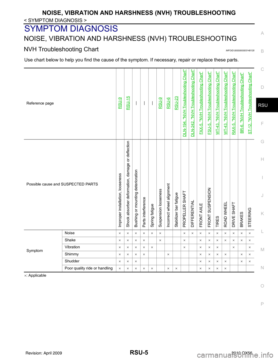
NVH Troubleshooting ChartINFOID:0000000005148128
Use chart below to help you find the cause of the symptom. If necessary, repair or replace these parts.
×: ApplicableReference page
RSU-9RSU-15
—
—
—
RSU-9RSU-6RSU-23
DLN-194, "
NVH Troubleshooting Chart
"
DLN-242, "
NVH Troubleshooting Chart
"
FAX-5, "
NVH Troubleshooting Chart
"
FSU-5, "
NVH Troubleshooting Chart
"
WT-43, "
NVH Troubleshooting Chart
"
WT-43, "
NVH Troubleshooting Chart
"
RAX-5, "
NVH Troubleshooting Chart
"
BR-6, "
NVH Troubleshooting Chart
"
ST-12, "
NVH Troubleshooting Chart
"
Possible cause and SUSPECTED PARTS
Improper installation, looseness
Shock absorber deformation, damage or deflection
Bushing or mounting deterioration
Parts interference
Spring fatigue
Suspension looseness
Incorrect wheel alignment
Stabilizer bar fatigue
PROPELLER SHAFT
DIFFERENTIAL
FRONT AXLE
FRONT SUSPENSION
TIRES
ROAD WHEEL
DRIVE SHAFT
BRAKES
STEERING
Symptom Noise
×××××× ××× ××××××
Shake ×××× × × × ××××××
Vibration ××××× × × ×× × ×
Shimmy ×××× × × ××× ××
Shudder ××× × ××× ××
Poor quality ride or handling ××××× ×× × ×××
Revision: April 20092010 QX56
Page 3193 of 4210
RSU-6
< ON-VEHICLE MAINTENANCE >
REAR SUSPENSION ASSEMBLY
ON-VEHICLE MAINTENANCE
REAR SUSPENSION ASSEMBLY
On-Vehicle Inspection and ServiceINFOID:0000000005148129
Check all of the component mountings for any excessive looseness, or back lash. Check the components for
any excessive wear, damage, or abnormal conditions. Repair or replace the components as necessary.
SHOCK ABSORBER INSPECTION
• Check the shock absorbers for any air leaks or damage, and replace as necessary.
• Check the hoses for any air leaks or damage, and replace as necessary.
Wheel Alignment InspectionINFOID:0000000005148130
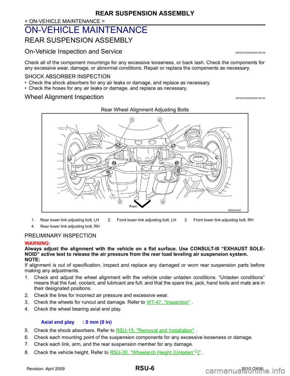
Rear Wheel Alignment Adjusting Bolts
PRELIMINARY INSPECTION
WARNING:
Always adjust the alignment with the vehicle on a flat surface. Use CONSULT-III “EXHAUST SOLE-
NOID” active test to release the air pressure from the rear load leveling air suspension system.
NOTE:
If alignment is out of specificat ion, inspect and replace any damaged or worn rear suspension parts before
making any adjustments.
1. Check and adjust the wheel alignment with the vehicle under unladen conditions. “Unladen conditions”
means that the fuel, coolant, and lubricant are full; and that the spare tire, jack, hand tools and mats are in
their designated positions.
2. Check the tires for incorrect air pressure and excessive wear.
3. Check the wheels for runout and damage. Refer to WT-47, "
Inspection" .
4. Check the wheel bearing axial end play.
5. Check the shock absorbers. Refer to RSU-15, "
Removal and Installation" .
6. Check each mounting point of the suspension components for any excessive looseness or damage.
7. Check each link, arm, and the rear suspension member for any damage.
8. Check the vehicle height. Refer to RSU-30, "
Wheelarch Height (Unladen*1)" .
WEIA0102E
1. Rear lower link adjusting bolt, LH 2. Front lower link adjusting bolt, LH 3. Front lower link adjusting bolt, RH
4. Rear lower link adjusting bolt, RH
Axial end play : 0 mm (0 in)
Revision: April 20092010 QX56
Page 3196 of 4210
REAR SUSPENSION ASSEMBLYRSU-9
< ON-VEHICLE REPAIR >
C
DF
G H
I
J
K L
M A
B
RSU
N
O P
ON-VEHICLE REPAIR
REAR SUSPENSION ASSEMBLY
ComponentINFOID:0000000005148131
Rear Suspension
AWEIA0143GB
1. Seat belt latch anchor 2. Stabilizer bar bushing3. Stabilizer bar clamp
4. Stabilizer bar 5. Connecting rod6. Front lower link
7. Knuckle 8. Bushing9. Rear lower link
10. Shock absorber 11. Suspension arm12. Lower rubber seat
Revision: April 20092010 QX56
Page 3197 of 4210
RSU-10
< ON-VEHICLE REPAIR >
REAR SUSPENSION ASSEMBLY
Rear Load Leveling Air Suspension System
13. Coil spring14. Upper rubber seat15. Rear suspension member
16. Spare tire bracket 17. Bound bumper Front
AWEIA0054GB
1. Rear load leveling air suspension
hose, RH 2. Shock absorber, RH
3. Height sensor
4. Rear load leveling air suspension hose, LH 5. Shock absorber, LH
6. Rear load leveling air suspension
compressor assembly
Front
Revision: April 20092010 QX56
Page 3198 of 4210
REAR SUSPENSION MEMBERRSU-11
< REMOVAL AND INSTALLATION >
C
DF
G H
I
J
K L
M A
B
RSU
N
O P
REMOVAL AND INSTALLATION
REAR SUSPENSION MEMBER
Removal and InstallationINFOID:0000000005148132
Rear Suspension
AWEIA0143GB
1. Seat belt latch anchor 2. Stabilizer bar bushing3. Stabilizer bar clamp
4. Stabilizer bar 5. Connecting rod6. Front lower link
7. Knuckle 8. Bushing9. Rear lower link
10. Shock absorber 11. Suspension arm12. Lower rubber seat
Revision: April 20092010 QX56
Page 3199 of 4210
RSU-12
< REMOVAL AND INSTALLATION >
REAR SUSPENSION MEMBER
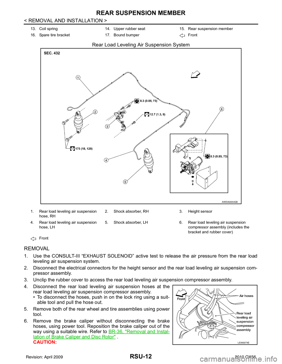
Rear Load Leveling Air Suspension System
REMOVAL
1. Use the CONSULT-III “EXHAUST SOLENOID” active test to release the air pressure from the rear load
leveling air suspension system.
2. Disconnect the electrical connectors for the height sensor and the rear load leveling air suspension com-
pressor assembly.
3. Unclip the rubber cover to access the rear load leveling air suspension compressor assembly.
4. Disconnect the rear load leveling air suspension hoses at the rear load leveling air suspension compressor assembly.
• To disconnect the hoses, push in on the lock ring using a suit-able tool and pull the hose out.
5. Remove both of the rear wheel and tire assemblies using power tool.
6. Remove the brake caliper without disconnecting the brake hoses, using power tool. Reposition the brake caliper out of the
way using a suitable wire. Refer to BR-36, "
Removal and Instal-
lation of Brake Caliper and Disc Rotor" .
CAUTION:
13. Coil spring 14. Upper rubber seat15. Rear suspension member
16. Spare tire bracket 17. Bound bumper Front
AWEIA0054GB
1. Rear load leveling air suspension
hose, RH 2. Shock absorber, RH
3. Height sensor
4. Rear load leveling air suspension hose, LH 5. Shock absorber, LH
6. Rear load leveling air suspension
compressor assembly (includes the
bracket and rubber cover)
Front
LEIA0074E
Revision: April 20092010 QX56