2010 INFINITI QX56 coolant
[x] Cancel search: coolantPage 783 of 4210

ENGINE COOLING FANCO-19
< ON-VEHICLE REPAIR >
C
DE
F
G H
I
J
K L
M A
CO
NP
O
INSTALLATION
Installation is in the reverse order of removal.
• Install cooling fan with its front mark “F” facing front of engine.
INSPECTION AFTER INSTALLATION
• Check for leaks of the engine coolant. Refer to
CO-10, "Inspection".
• Start and warm up the engine. Visually make sure that there are no leaks of the engine coolant.
Removal and Installati on (Motor Driven Type)INFOID:0000000005149048
REMOVAL
1. Remove the front bumper fascia. Refer to EXT-13, "Removal and Installation".
2. Disconnect the secondary hood release cable.
3. Disconnect harness connector (A) from fan motor.
4. Remove the bolt and remove the fan grille and motor assembly.
INSTALLATION
Installation is in the reverse order of removal.
• Cooling fan is controlled by ECM. For details, refer to EC-36, "
Description".
AWBIA0668ZZ
Revision: April 20092010 QX56
Page 784 of 4210

CO-20
< ON-VEHICLE REPAIR >
WATER PUMP
WATER PUMP
Exploded ViewINFOID:0000000005149049
Removal and InstallationINFOID:0000000005149050
CAUTION:
• When removing water pump, be careful not to get engine coolant on drive belt.
• Water pump cannot be disassembled and should be replaced as a unit.
REMOVAL
1. Drain engine coolant from the radiator. Refer to CO-11, "Changing Engine Coolant".
CAUTION:
Perform when the engine is cold.
2. Remove the engine cooling fan (crankshaft driven type). Refer to CO-18, "
Removal and Installation
(Crankshaft Driven Type)".
3. Remove the water pump pulley.
4. Remove the water pump. • Engine coolant will leak from the cylinder block, so have a receptacle ready below.
CAUTION:
Handle water pump vane so that it does not contact any other parts.
INSPECTION AFTER REMOVAL
• Visually check that there is no signi ficant dirt or rust on the water
pump body and vane.
• Make sure there is no looseness in the vane shaft, and that it turns smoothly when rotated by hand.
• Replace the water pump assembly, if necessary.
INSTALLATION
Installation is in the reverse order of removal.
• After installation bleed the air from the cooling system. Refer to CO-11, "
Changing Engine Coolant".
1. Gasket2. Water pump3. Water pump pulley
KBIA2543E
KBIA2552E
Revision: April 20092010 QX56
Page 785 of 4210

WATER PUMPCO-21
< ON-VEHICLE REPAIR >
C
DE
F
G H
I
J
K L
M A
CO
NP
O
INSPECTION AFTER INSTALLATION
• Check for leaks of engine coolant. Refer to
CO-10, "Inspection".
• Start and warm up engine. Visually c heck for leaks of the engine coolant.
Revision: April 20092010 QX56
Page 786 of 4210

CO-22
< ON-VEHICLE REPAIR >
THERMOSTAT AND WATER PIPING
THERMOSTAT AND WATER PIPING
Exploded ViewINFOID:0000000005149051
Removal and InstallationINFOID:0000000005149052
REMOVAL
Removal of Thermostat
1. Partially drain engine coolant from the radiator. Refer to CO-11, "Changing Engine Coolant".
CAUTION:
Perform when engine is cold.
2. Disconnect the water suction hose from the water inlet.
3. Remove the water inlet and thermostat.
Removal of Thermostat Housing, Water Outlet and Heater Pipe
1. Remove the intake manifold. Refer to EM-26, "Removal and Installation".
2. Remove the thermostat housing, water outlet and heater pipe.
Removal of Water Cut Valve
1. Partially drain engine coolant from the radiator. Refer to CO-11, "Changing Engine Coolant".
CAUTION:
1. Heater pipe 2. Gasket 3. Water outlet
4. Gasket 5. O-ring 6. O-ring
7. Thermostat housing 8. Rubber ring 9. Thermostat
10. Water inlet 11. Water suction hose 12. Water suction pipe
13. Gasket 14. Heater pipe
KBIA2501E
Revision: April 20092010 QX56
Page 787 of 4210

THERMOSTAT AND WATER PIPINGCO-23
< ON-VEHICLE REPAIR >
C
DE
F
G H
I
J
K L
M A
CO
NP
O
Perform when the engine is cold.
2. Disconnect the water cut valve connector.
3. Disconnect the water hoses from the water cut valve.
4. Remove the water cut valve.
INSPECTION AFTER REMOVAL
• Place a thread so that it is caught in the valve of the thermostat.
Immerse fully in a container filled with water. Heat while stirring.
• The valve opening temperature is the temperature at which the valve opens and falls from the thread.
• Continue heating. Check the full-open lift amount.
• After checking the full-open lift amount, lower the water tempera-
ture and check the valve closing temperature.
Standard values:
INSTALLATION
Installation is in the reverse order of removal.
Installation of Thermostat
• Install the thermostat with the whole circumference of each flange
part fit securely inside the rubber ring as shown.
• Install the thermostat with the jiggle valve facing upwards.
Installation of Water Outlet Pipe and Heater Pipe
First apply a neutral detergent to the O- rings, then quickly insert the insertion parts of the water outlet pipe and
heater pipe into the installation holes.
INSPECTION AFTER INSTALLATION
• Check for leaks of the engine coolant. Refer to CO-10, "Inspection".
• Start and warm up the engine. Visually check for leaks of the engine coolant.
SLC252B
Thermostat
Valve opening temperature 80 - 84°C (176 - 183 ° F)
Full-open lift amount More than 10 mm/ 95°C (0.39 in/ 203° F)
Valve closing temperature 77°C (171 °F) or higher
KBIA2502E
Revision: April 20092010 QX56
Page 788 of 4210

CO-24
< SERVICE DATA AND SPECIFICATIONS (SDS)
SERVICE DATA AND SPECIFICATIONS (SDS)
SERVICE DATA AND SPECIFICATIONS (SDS)
SERVICE DATA AND SPECIFICATIONS (SDS)
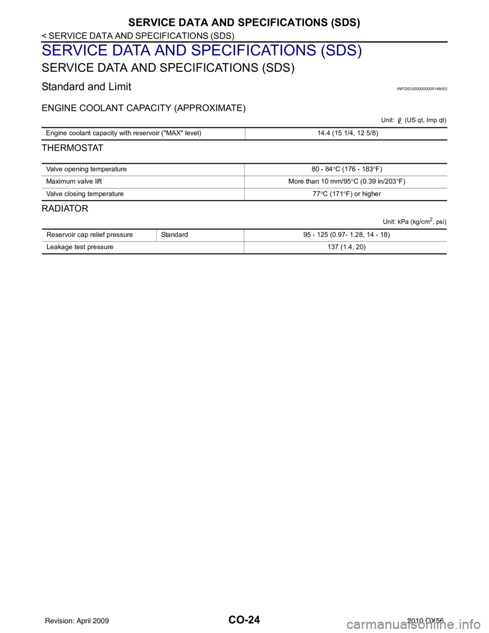
Standard and LimitINFOID:0000000005149053
ENGINE COOLANT CAPACITY (APPROXIMATE)
Unit: (US qt, Imp qt)
THERMOSTAT
RADIATOR
Unit: kPa (kg/cm2, psi)
Engine coolant capacity with reservoir ("MAX" level)14.4 (15 1/4, 12 5/8)
Valve opening temperature80 - 84°C (176 - 183 °F)
Maximum valve lift More than 10 mm/95°C (0.39 in/203 °F)
Valve closing temperature 77°C (171 °F) or higher
Reservoir cap relief pressure Standard 95 - 125 (0.97- 1.28, 14 - 18)
Leakage test pressure 137 (1.4, 20)
Revision: April 20092010 QX56
Page 1360 of 4210

EC-7
C
DE
F
G H
I
J
K L
M
EC A
N
O P
CONSULT-lll Reference Va
lue in Data Monitor
Mode ................................................................... ..
422
ECM Harness Connector Terminal Layout ...........425
ECM Terminal and Reference Value ....................425
Wiring Diagram - ENGINE CONTROL SYSTEM - ..435
Fail-Safe Chart .................................................... ..456
DTC Inspection Priority Chart ............................. ..458
DTC Index ........................................................... ..459
Emission-related Diagnostic Information ...............463
SYMPTOM DIAGNOSIS ..... .......................477
ENGINE CONTROL SYSTEM SYMPTOMS .. ..477
Symptom Matrix Chart ........................................ ..477
NORMAL OPERATING CONDITION ...............481
Fuel Cut Control (at No Load and High Engine
Speed) ................................................................. ..
481
PRECAUTION ............................................482
PRECAUTIONS .............................................. ..482
Precaution for Supplemental Restraint System
(SRS) "AIR BAG" and "SEAT BELT PRE-TEN-
SIONER" ............................................................. ..
482
On Board Diagnosis (OBD) System of Engine and
A/T .........................................................................
482
Precaution .............................................................482
PREPARATION .........................................486
PREPARATION .............................................. ..486
Special Service Tool ........................................... ..486
Commercial Service Tool ......................................487
ON-VEHICLE MAINTENANCE ..................489
FUEL PRESSURE ...........................................489
Fuel Pressure Check ........................................... ..489
EVAP LEAK CHECK ......................................491
How to Detect Fuel Vapor Leakage .......................491
ON-VEHICLE REPAIR ...............................493
EVAP CANISTER ............................................493
Removal and Installation ..................................... ..493
Component Inspection ...........................................493
INTAKE VALVE TIMING CONTROL ..............494
Intake Valve Timing Control Solenoid Valve (LH) ..494
Intake Valve Timing Cont rol Solenoid Valve (RH) ..494
Intake Valve Timing Control Position Sensor (LH) ..495
Intake Valve Timing Control Position Sensor (RH) ..495
Camshaft Position Sensor (PHASE) .....................495
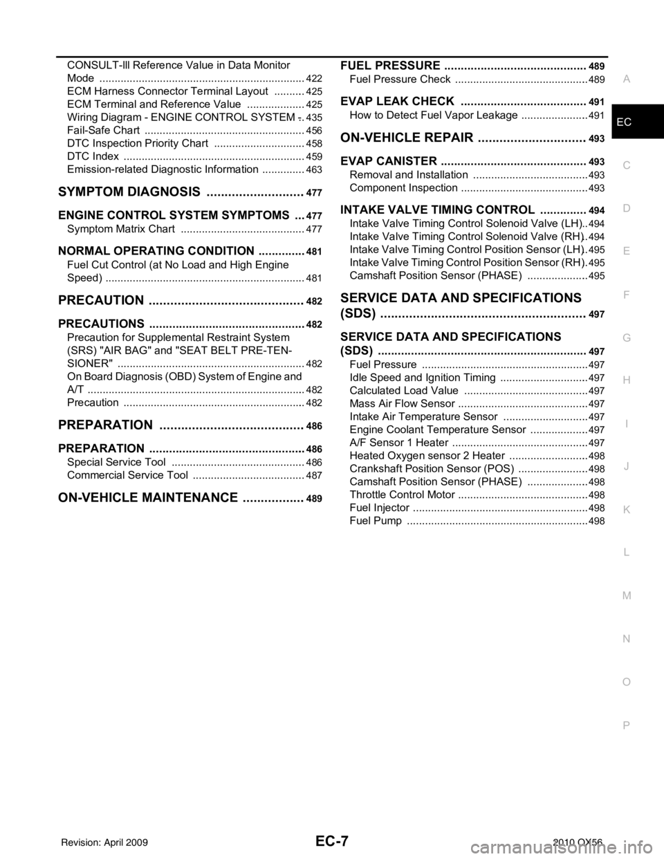
SERVICE DATA AND SPECIFICATIONS
(SDS) ............... .......................................... .
497
SERVICE DATA AND SPECIFICATIONS
(SDS) ...............................................................
497
Fuel Pressure ...................................................... ..497
Idle Speed and Ignition Timing ..............................497
Calculated Load Value ..........................................497
Mass Air Flow Sensor ............................................497
Intake Air Temperature Sensor .............................497
Engine Coolant Temperature Sensor ....................497
A/F Sensor 1 Heater ..............................................497
Heated Oxygen sensor 2 Heater ...........................498
Crankshaft Position Sensor (POS) ........................498
Camshaft Position Sensor (PHASE) .....................498
Throttle Control Motor ............................................498
Fuel Injector ...........................................................498
Fuel Pump .............................................................498
Revision: April 20092010 QX56
Page 1366 of 4210
![INFINITI QX56 2010 Factory Service Manual INSPECTION AND ADJUSTMENTEC-13
< BASIC INSPECTION > [VK56DE]
C
D
E
F
G H
I
J
K L
M A
EC
NP
O
INSPECTION AND ADJUSTMENT
Basic InspectionINFOID:0000000005149055
1.INSPECTION START
1. Check service recor INFINITI QX56 2010 Factory Service Manual INSPECTION AND ADJUSTMENTEC-13
< BASIC INSPECTION > [VK56DE]
C
D
E
F
G H
I
J
K L
M A
EC
NP
O
INSPECTION AND ADJUSTMENT
Basic InspectionINFOID:0000000005149055
1.INSPECTION START
1. Check service recor](/manual-img/42/57032/w960_57032-1365.png)
INSPECTION AND ADJUSTMENTEC-13
< BASIC INSPECTION > [VK56DE]
C
D
E
F
G H
I
J
K L
M A
EC
NP
O
INSPECTION AND ADJUSTMENT
Basic InspectionINFOID:0000000005149055
1.INSPECTION START
1. Check service records for any recent repairs that may indicate a related malfunction, or a current need for scheduled maintenance.
2. Open engine hood and check the following:
- Harness connectors for improper connections
- Wiring harness for improper connections, pinches and cut
- Vacuum hoses for splits, kinks and improper connections
- Hoses and ducts for leaks
- Air cleaner clogging
- Gasket
3. Confirm that electrical or mechanical loads are not applied.
- Headlamp switch is OFF.
- Air conditioner switch is OFF.
- Rear window defogger switch is OFF.
- Steering wheel is in the straight-ahead position, etc.
4. Start engine and warm it up until engine coolant temperature indicator points the middle of gauge.
Ensure engine stays below 1,000 rpm.
5. Run engine at about 2,000 rpm for about 2 minutes under no load.
6. Make sure that no DTC is displayed with CONSULT-III or GST.
OK or NG
OK >> GO TO 3.
NG >> GO TO 2.
2.REPAIR OR REPLACE
Repair or replace components as necessary according to corresponding Diagnostic Procedure.
>> GO TO 3.
3.CHECK TARGET IDLE SPEED
With CONSULT-III
1. Run engine at about 2,000 rpm for about 2 minutes under no load.
SEF983U
SEF976U
SEF977U
Revision: April 20092010 QX56