Page 4194 of 4210
WIPER AND WASHER SYSTEM SYMPTOMSWW-73
< SYMPTOM DIAGNOSIS >
C
DE
F
G H
I
J
K
M A
B
WW
N
O P
Rear wiper does not
stop. ON only
• Combination switch
•BCM Rear wiper motor circuit
Refer to WW-28, "
Compo-
nent Function Check".
INT only • Combination switch
•BCM Combination switch
Refer to BCS-56, "
Symptom
Ta b l e".
Rear wiper does not
operate normally. Wiper is not linked to
the washer operation.
• Combination switch
• Harness between rear wiper motor and BCM
•BCM
Combination switch
Refer to BCS-56, "
Symptom
Ta b l e".
BCM —
Rear wiper does not
return to the Stop posi-
tion (Stops after a five-
second operation). •BCM
• Harness between rear wiper motor and BCM
• Rear wiper motor Rear wiper auto stop signal
circuit
Refer to WW-30, "
Compo-
nent Function Check".
Rear wiper stops after
operating for five sec-
onds when ignition
switch is turned ON.
Symptom
Probable malfunction location Inspection item
Revision: April 20092010 QX56
Page 4195 of 4210
WW-74
< SYMPTOM DIAGNOSIS >
NORMAL OPERATING CONDITION
NORMAL OPERATING CONDITION
DescriptionINFOID:0000000005146797
FRONT WIPER MOTOR PROTECTION FUNCTION
• IPDM E/R may stop the front wiper to protect the front wiper motor if any obstruction (operation resistance)
such as a large amount of snow is detected during the front wiper operation.
• At that time turn OFF the front wiper and remove t he foreign object. Then wait for approximately 20 seconds
or more and reactivate the front wiper. The wiper will operate normally.
REAR WIPER MOTOR PROTECTION FUNCTION
• BCM may stop rear wiper to protect the rear wiper motor when the rear wiper is stopped for 5 seconds or more due to a snowfall.
• Rear wiper operates normally one minute after the obstacles are removed with rear wiper OFF.
Revision: April 20092010 QX56
Page 4196 of 4210

FRONT WIPER DOES NOT OPERATEWW-75
< SYMPTOM DIAGNOSIS >
C
DE
F
G H
I
J
K
M A
B
WW
N
O P
FRONT WIPER DO ES NOT OPERATE
DescriptionINFOID:0000000005146798
The front wiper does not operate under any operation conditions.
Diagnosis ProcedureINFOID:0000000005146799
Regarding Wiring Diagram information, refer to WW-31, "Wiring Diagram".
1. CHECK WIPER RELAY OPERATION
IPDM E/R AUTO ACTIVE TEST
1. Start IPDM E/R auto active test. Refer to PCS-8, "
System Description".
2. Check that the front wiper operates at the LO/HI operation.
CONSULT-III ACTIVE TEST
1. Select "FRONT WIPER" of IPDM E/R active test item.
2. While operating the test item, check front wiper operation.
Is front wiper operation normal?
YES >> GO TO 5
NO >> GO TO 2
2. CHECK FRONT WIPER MOTOR FUSE
1. Turn the ignition switch OFF.
2. Check that the following fuse is not blown.
Is the fuse blown?
YES >> Replace the fuse after repairing the applicable circuit.
NO >> GO TO 3
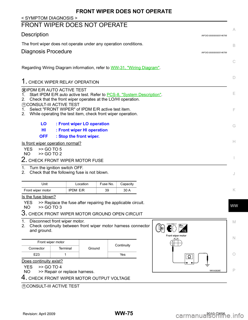
3. CHECK FRONT WIPER MOTOR GROUND OPEN CIRCUIT
1. Disconnect front wiper motor.
2. Check continuity between front wiper motor harness connector and ground.
Does continuity exist?
YES >> GO TO 4
NO >> Repair or replace harness.
4. CHECK FRONT WIPER MOTOR OUTPUT VOLTAGE
CONSULT-III ACTIVE TEST LO : Front wiper LO operation
HI : Front wiper HI operation
OFF : Stop the front wiper.
Unit Location Fuse No. Capacity
Front wiper motor IPDM E/R39 30 A
Front wiper motor
GroundContinuity
Connector Terminal
E23 1 Yes
WKIA2828E
Revision: April 20092010 QX56
Page 4197 of 4210

WW-76
< SYMPTOM DIAGNOSIS >
FRONT WIPER DOES NOT OPERATE
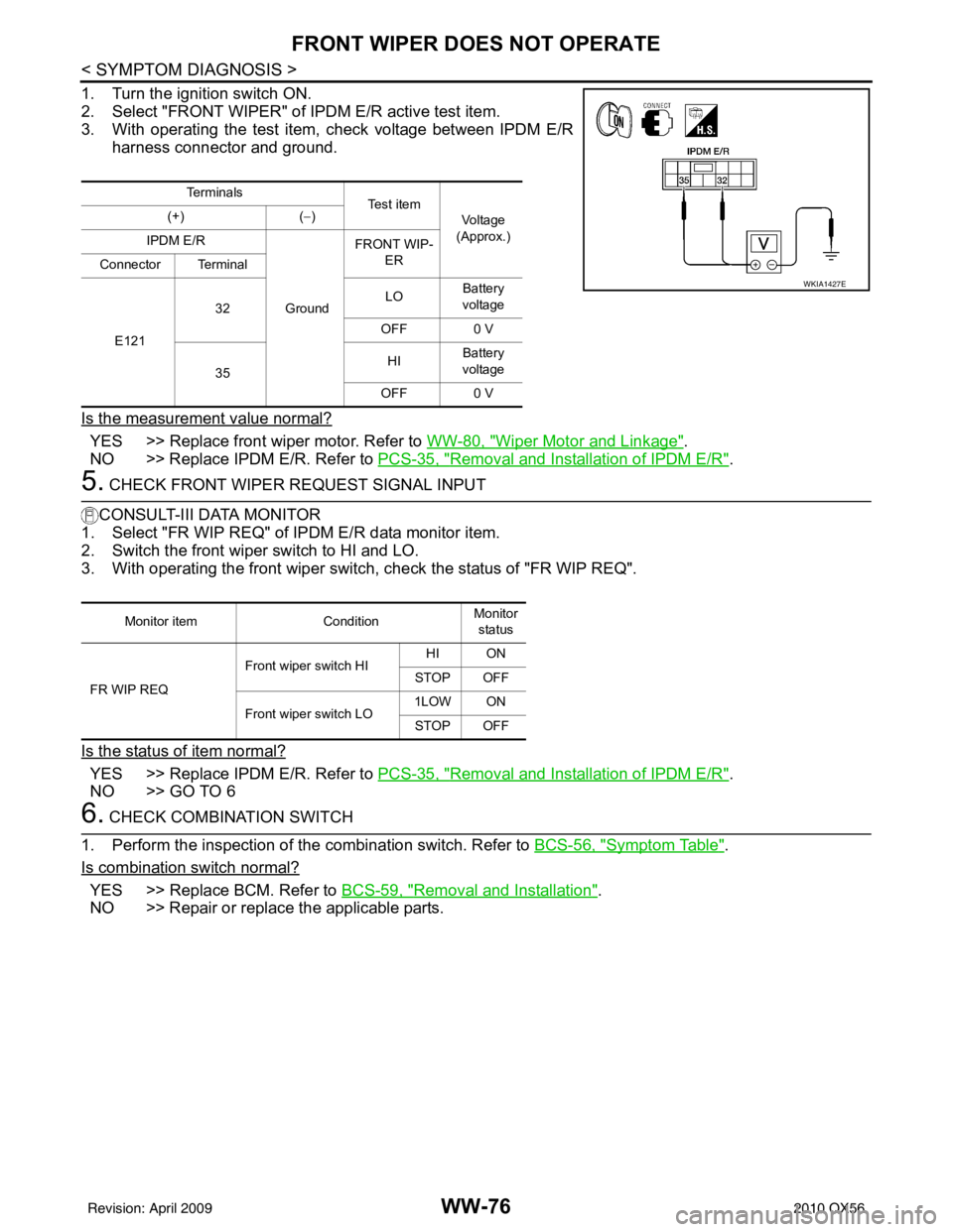
1. Turn the ignition switch ON.
2. Select "FRONT WIPER" of IPDM E/R active test item.
3. With operating the test item, check voltage between IPDM E/R
harness connector and ground.
Is the measurement value normal?
YES >> Replace front wiper motor. Refer to WW-80, "Wiper Motor and Linkage".
NO >> Replace IPDM E/R. Refer to PCS-35, "
Removal and Installation of IPDM E/R".
5. CHECK FRONT WIPER REQUEST SIGNAL INPUT
CONSULT-III DATA MONITOR
1. Select "FR WIP REQ" of IPDM E/R data monitor item.
2. Switch the front wiper switch to HI and LO.
3. With operating the front wiper switch , check the status of "FR WIP REQ".
Is the status of item normal?
YES >> Replace IPDM E/R. Refer to PCS-35, "Removal and Installation of IPDM E/R".
NO >> GO TO 6
6. CHECK COMBINATION SWITCH
1. Perform the inspection of the combination switch. Refer to BCS-56, "
Symptom Table".
Is combination switch normal?
YES >> Replace BCM. Refer to BCS-59, "Removal and Installation".
NO >> Repair or replace the applicable parts.
Te r m i n a l s Te s t i t e m
Voltage
(Approx.)
(+)
(− )
IPDM E/R
GroundFRONT WIP-
ER
Connector Terminal
E121 32
LO
Battery
voltage
OFF 0 V
35 HI
Battery
voltage
OFF 0 V
WKIA1427E
Monitor item ConditionMonitor
status
FR WIP REQ Front wiper switch HI
HI ON
STOP OFF
Front wiper switch LO 1LOW ON
STOP OFF
Revision: April 20092010 QX56
Page 4200 of 4210

FRONT WIPER ARMWW-79
< ON-VEHICLE REPAIR >
C
DE
F
G H
I
J
K
M A
B
WW
N
O P
ON-VEHICLE REPAIR
FRONT WIPER ARM
Front Wiper ArmsINFOID:0000000005146801
REMOVAL AND INSTALLATION
Removal
1. Remove wiper arm covers and wiper arm nuts.
2. Remove front RH wiper arm and front LH wiper arm.
3. Remove front RH blade assembly and front LH blade assembly.
Installation
1. Operate wiper motor one full cycle, then turn "OFF" (Auto Stop).
2. Clean up the pivot area as shown. This will reduce possibility of wiper arm looseness.
3. Install front RH blade assembly and front LH blade assembly on the wiper arms.
4. Install front RH wiper arm and front LH wiper arm.
5. Tighten wiper arm nuts to specified torque, and install wiper arm covers. Refer to WW-80, "
Wiper Motor
and Linkage".
6. Ensure that wiper blades stop within proper clear ance. Refer to "FRONT WIPER ARM ADJUSTMENT".
FRONT WIPER ARM ADJUSTMENT
1. Operate wiper motor one full cycle, then turn "OFF" (Auto Stop).
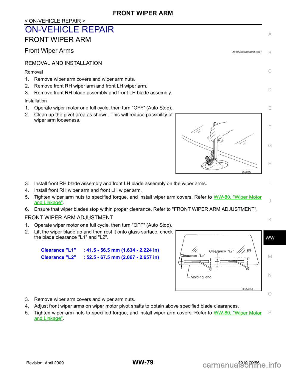
2. Lift the wiper blade up and then rest it onto glass surface, check
the blade clearance "L1" and "L2".
3. Remove wiper arm covers and wiper arm nuts.
4. Adjust front wiper arms on wiper motor pivot shafts to obtain above specified blade clearances.
5. Tighten wiper arm nuts to specified torque, and install wiper arm covers. Refer to WW-80, "
Wiper Motor
and Linkage".
SEL024J
Clearance "L1" : 41.5 - 56.5 mm (1.634 - 2.224 in)
Clearance "L2" : 52.5 - 67.5 mm (2.067 - 2.657 in)
SEL543TA
Revision: April 20092010 QX56
Page 4201 of 4210

WW-80
< ON-VEHICLE REPAIR >
FRONT WIPER DRIVE ASSEMBLY
FRONT WIPER DRIVE ASSEMBLY
Wiper Motor and LinkageINFOID:0000000005146802
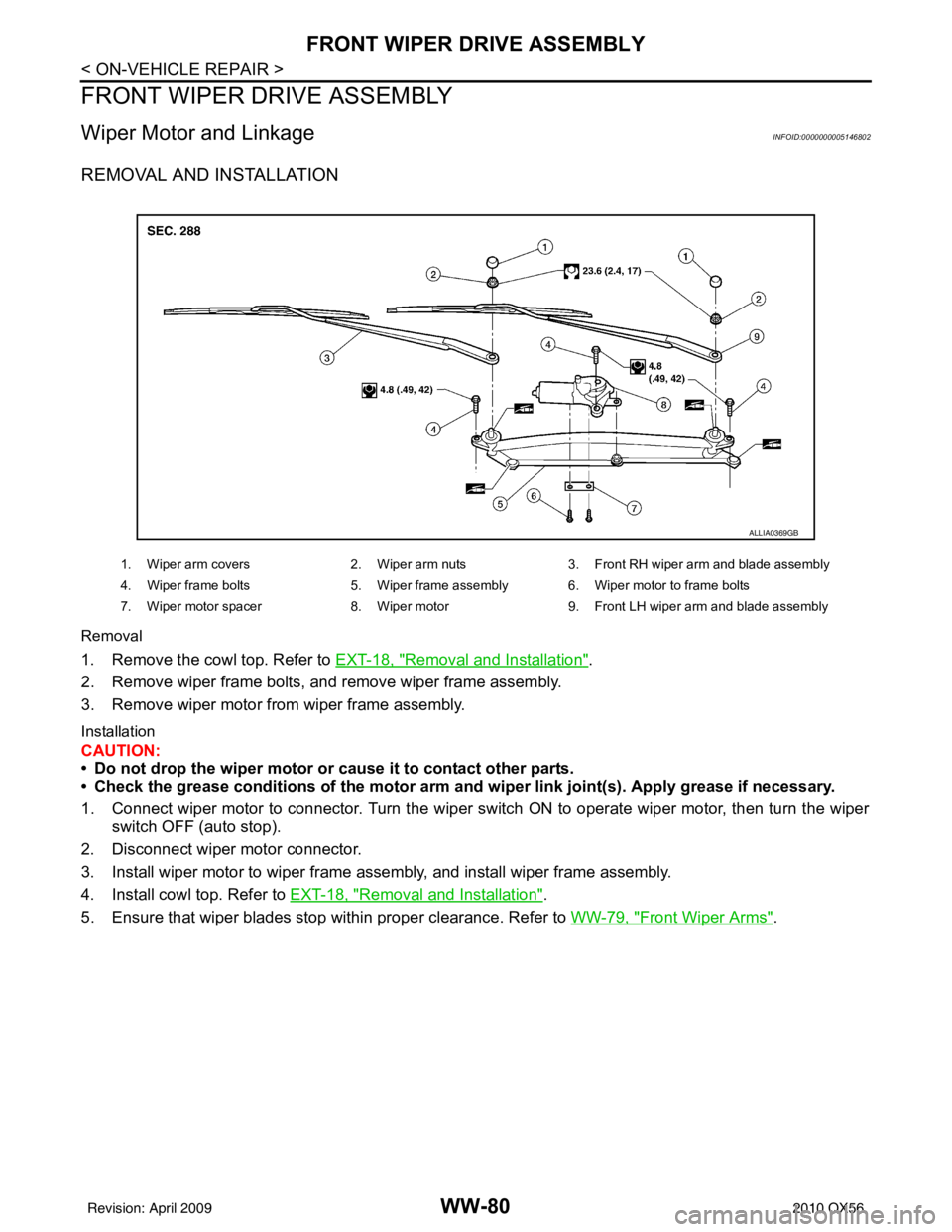
REMOVAL AND INSTALLATION
Removal
1. Remove the cowl top. Refer to EXT-18, "Removal and Installation".
2. Remove wiper frame bolts, and remove wiper frame assembly.
3. Remove wiper motor from wiper frame assembly.
Installation
CAUTION:
• Do not drop the wiper motor or cause it to contact other parts.
• Check the grease conditions of the motor arm a nd wiper link joint(s). Apply grease if necessary.
1. Connect wiper motor to connector. Turn the wiper switch ON to operate wiper motor, then turn the wiper switch OFF (auto stop).
2. Disconnect wiper motor connector.
3. Install wiper motor to wiper frame assembly, and install wiper frame assembly.
4. Install cowl top. Refer to EXT-18, "
Removal and Installation".
5. Ensure that wiper blades stop within proper clearance. Refer to WW-79, "
Front Wiper Arms".
ALLIA0369GB
1. Wiper arm covers2. Wiper arm nuts3. Front RH wiper arm and blade assembly
4. Wiper frame bolts 5. Wiper frame assembly 6. Wiper motor to frame bolts
7. Wiper motor spacer 8. Wiper motor9. Front LH wiper arm and blade assembly
Revision: April 20092010 QX56
Page 4206 of 4210
FRONT WIPER AND WASHER SWITCHWW-85
< ON-VEHICLE REPAIR >
C
DE
F
G H
I
J
K
M A
B
WW
N
O P
FRONT WIPER AND WASHER SWITCH
Wiper and Washer SwitchINFOID:0000000005146807
REMOVAL AND INSTALLATION
Removal
1. Remove steering column covers.
2. Remove wiper washer switch connector.
3. Pinch tabs at wiper and washer switch base and slide switch away from steering column to remove.
Installation
Installation is in the reverse order of removal.
WKIA0071E
Revision: April 20092010 QX56
Page 4207 of 4210
WW-86
< ON-VEHICLE REPAIR >
REAR WIPER AND WASHER SYSTEM
REAR WIPER AND WASHER SYSTEM
Rear Wiper ArmINFOID:0000000005146808
REMOVAL AND INSTALLATION
Removal
1. Remove wiper arm cover, and remove rear wiper arm nut.
2. Remove the wiper arm.
3. Remove wiper blade.
Installation
1. Operate rear wiper motor one full cycle, then turn "off " (Auto Stop).
2. Clean up the pivot area as illustrated. This will reduce the possi-bility of wiper arm looseness.
3. Install wiper blade.
4. Install rear wiper arm so that the arm rests in the stopper and tighten rear wiper arm nut.
5. Install wiper arm cover.
Rear Wiper MotorINFOID:0000000005146809
REMOVAL AND INSTALLATION
LKIA0608E
SEL024J
Revision: April 20092010 QX56