Page 3854 of 4210

ROAD TESTTM-159
< ON-VEHICLE MAINTENANCE >
CEF
G H
I
J
K L
M A
B
TM
N
O P
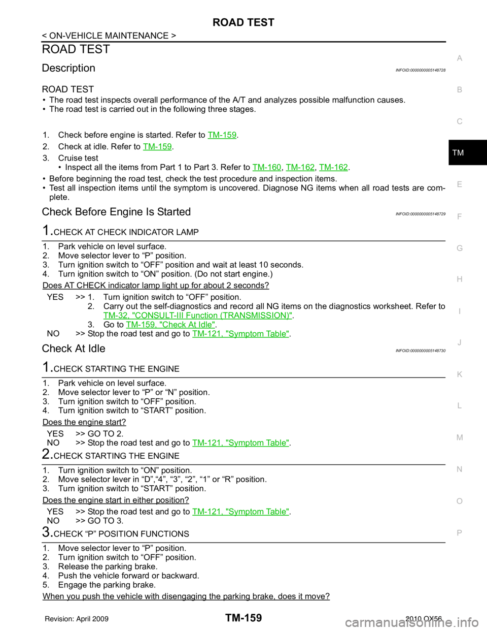
ROAD TEST
DescriptionINFOID:0000000005148728
ROAD TEST
• The road test inspects overall performance of the A/T and analyzes possible malfunction causes.
• The road test is carried out in the following three stages.
1. Check before engine is started. Refer to TM-159
.
2. Check at idle. Refer to TM-159
.
3. Cruise test • Inspect all the items from Part 1 to Part 3. Refer to TM-160
, TM-162, TM-162.
• Before beginning the road test, check the test procedure and inspection items.
• Test all inspection items until the symptom is uncov ered. Diagnose NG items when all road tests are com-
plete.
Check Before Engine Is StartedINFOID:0000000005148729
1.CHECK AT CHECK INDICATOR LAMP
1. Park vehicle on level surface.
2. Move selector lever to “P” position.
3. Turn ignition switch to “OFF” position and wait at least 10 seconds.
4. Turn ignition switch to “ON” position. (Do not start engine.)
Does AT CHECK indicator lamp light up for about 2 seconds?
YES >> 1. Turn ignition switch to “OFF” position. 2. Carry out the self-diagnostics and record all NG items on the diagnostics worksheet. Refer toTM-32, "
CONSULT-III Function (TRANSMISSION)".
3. Go to TM-159, "
Check At Idle".
NO >> Stop the road test and go to TM-121, "
Symptom Table".
Check At IdleINFOID:0000000005148730
1.CHECK STARTING THE ENGINE
1. Park vehicle on level surface.
2. Move selector lever to “P” or “N” position.
3. Turn ignition switch to “OFF” position.
4. Turn ignition switch to “START” position.
Does the engine start?
YES >> GO TO 2.
NO >> Stop the road test and go to TM-121, "
Symptom Table".
2.CHECK STARTING THE ENGINE
1. Turn ignition switch to “ON” position.
2. Move selector lever in “D”,“4”, “3”, “2”, “1” or “R” position.
3. Turn ignition switch to “START” position.
Does the engine start in either position?
YES >> Stop the road test and go to TM-121, "Symptom Table".
NO >> GO TO 3.
3.CHECK “P” POSITION FUNCTIONS
1. Move selector lever to “P” position.
2. Turn ignition switch to “OFF” position.
3. Release the parking brake.
4. Push the vehicle forward or backward.
5. Engage the parking brake.
When you push the vehicle with disengaging the parking brake, does it move?
Revision: April 20092010 QX56
Page 3855 of 4210

TM-160
< ON-VEHICLE MAINTENANCE >
ROAD TEST
YES >> Record the malfunction, GO TO 4.
NO >> GO TO 4.
4.CHECK “N” POSITION FUNCTIONS
1. Start the engine.
2. Move selector lever to “N” position.
3. Release the parking brake.
Does vehicle move forward or backward?
YES >> Record the malfunction, GO TO 5.
NO >> GO TO 5.
5.CHECK SHIFT SHOCK
1. Engage the brake.
2. Move selector lever to “D” position.
When the transmission is shifted from
“N” to “D”, is there an excessive shock?
YES >> Record the malfunction, GO TO 6.
NO >> GO TO 6.
6.CHECK “R” POSITION FUNCTIONS
1. Engage the brake.
2. Move selector lever to “R” position.
3. Release the brake for 4 to 5 seconds.
Does the vehicle creep backward?
YES >> GO TO 7.
NO >> Record the malfunction, GO TO 7.
7.CHECK “D” POSITION FUNCTIONS
Inspect whether the vehicle creeps forward when the transmission is put into the “D” position.
Does the vehicle creep forward in the
“D” positions?
YES >> Go to TM-160, "Cruise Test - Part 1".
NO >> Record the malfunction and go to TM-160, "
Cruise Test - Part 1".
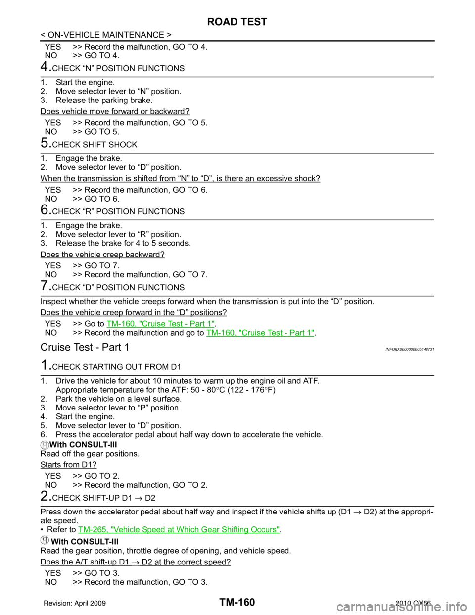
Cruise Test - Part 1INFOID:0000000005148731
1.CHECK STARTING OUT FROM D1
1. Drive the vehicle for about 10 minutes to warm up the engine oil and ATF. Appropriate temperature for the ATF: 50 - 80° C (122 - 176°F)
2. Park the vehicle on a level surface.
3. Move selector lever to “P” position.
4. Start the engine.
5. Move selector lever to “D” position.
6. Press the accelerator pedal about half way down to accelerate the vehicle.
With CONSULT-III
Read off the gear positions.
Starts from D1?
YES >> GO TO 2.
NO >> Record the malfunction, GO TO 2.
2.CHECK SHIFT-UP D1 → D2
Press down the accelerator pedal about half way and inspect if the vehicle shifts up (D1 → D2) at the appropri-
ate speed.
• Refer to TM-265, "
Vehicle Speed at Which Gear Shifting Occurs".
With CONSULT-III
Read the gear position, throttle degree of opening, and vehicle speed.
Does the A/T shift-up D1
→ D2 at the correct speed?
YES >> GO TO 3.
NO >> Record the malfunction, GO TO 3.
Revision: April 20092010 QX56
Page 3857 of 4210

TM-162
< ON-VEHICLE MAINTENANCE >
ROAD TEST
With CONSULT-III
Read the gear position and engine speed.
When the A/T shift-down D5
→ D4, does the engine speed drop smoothly back to idle?
YES >> 1. Stop the vehicle. 2. Go to TM-162, "
Cruise Test - Part 2".
NO >> Record the malfunction and go to TM-162, "
Cruise Test - Part 2".
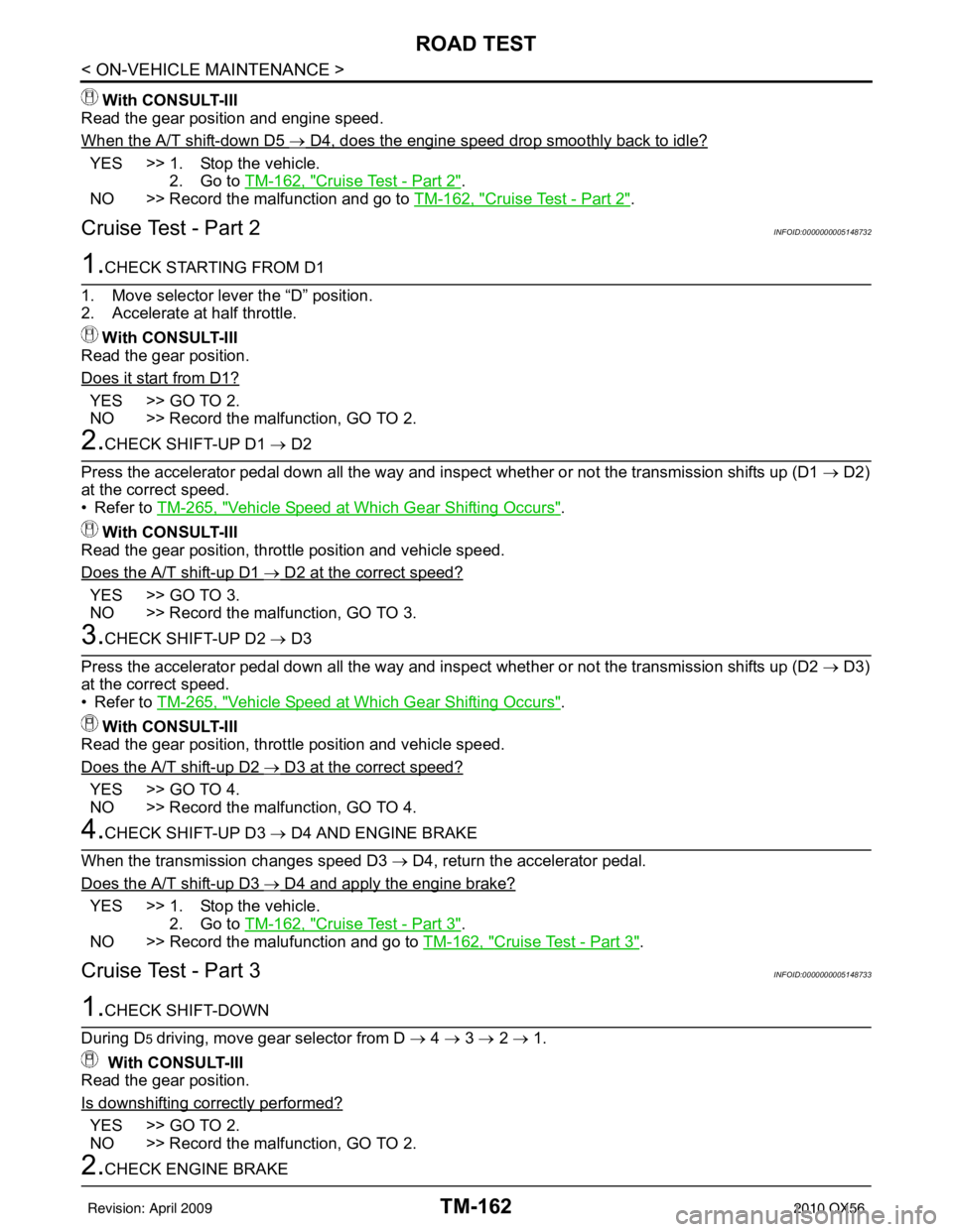
Cruise Test - Part 2INFOID:0000000005148732
1.CHECK STARTING FROM D1
1. Move selector lever the “D” position.
2. Accelerate at half throttle. With CONSULT-III
Read the gear position.
Does it start from D1?
YES >> GO TO 2.
NO >> Record the malfunction, GO TO 2.
2.CHECK SHIFT-UP D1 → D2
Press the accelerator pedal down all the way and ins pect whether or not the transmission shifts up (D1 → D2)
at the correct speed.
• Refer to TM-265, "
Vehicle Speed at Which Gear Shifting Occurs".
With CONSULT-III
Read the gear position, throttle position and vehicle speed.
Does the A/T shift-up D1
→ D2 at the correct speed?
YES >> GO TO 3.
NO >> Record the malfunction, GO TO 3.
3.CHECK SHIFT-UP D2 → D3
Press the accelerator pedal down all the way and ins pect whether or not the transmission shifts up (D2 → D3)
at the correct speed.
• Refer to TM-265, "
Vehicle Speed at Which Gear Shifting Occurs".
With CONSULT-III
Read the gear position, throttle position and vehicle speed.
Does the A/T shift-up D2
→ D3 at the correct speed?
YES >> GO TO 4.
NO >> Record the malfunction, GO TO 4.
4.CHECK SHIFT-UP D3 → D4 AND ENGINE BRAKE
When the transmission changes speed D3 → D4, return the accelerator pedal.
Does the A/T shift-up D3
→ D4 and apply the engine brake?
YES >> 1. Stop the vehicle. 2. Go to TM-162, "
Cruise Test - Part 3".
NO >> Record the malufunction and go to TM-162, "
Cruise Test - Part 3".
Cruise Test - Part 3INFOID:0000000005148733
1.CHECK SHIFT-DOWN
During D
5 driving, move gear selector from D → 4 → 3 → 2 → 1.
With CONSULT-III
Read the gear position.
Is downshifting correctly performed?
YES >> GO TO 2.
NO >> Record the malfunction, GO TO 2.
2.CHECK ENGINE BRAKE
Revision: April 20092010 QX56
Page 3865 of 4210
TM-170
< ON-VEHICLE REPAIR >
OIL PAN
OIL PAN
Oil PanINFOID:0000000005148740
REMOVAL AND INSTALLATION
Removal
1. Drain A/T fluid. Refer to TM-150, "Changing the A/T Fluid (ATF)".
2. Remove oil pan clips (1).
3. Remove oil pan (2).
4. Remove oil pan gasket. • : Vehicle front
• : Oil pan bolts
• Drain plug (3)
5. Check foreign materials in oil pan to help determine c ause of malfunction. If the A/T fluid is very dark, has
some burned smell, or contains foreign particles, friction material (clutches, band) may need replacement.
A tacky film that will not wipe clean indicates varnish build up. Varnish can cause valves, servo, and
clutches to stick and can inhibit pump pressure.
CAUTION:
If friction material is detected, flush the transmission cooler after repair. Refer to TM-152, "
A/T
Fluid Cooler Cleaning".
6. Remove magnets from oil pan.
Installation
1. Install the oil pan magnets as shown.
AWDIA0023ZZ
SCIA5200E
SCIA5200E
Revision: April 20092010 QX56
Page 3866 of 4210

OIL PANTM-171
< ON-VEHICLE REPAIR >
CEF
G H
I
J
K L
M A
B
TM
N
O P
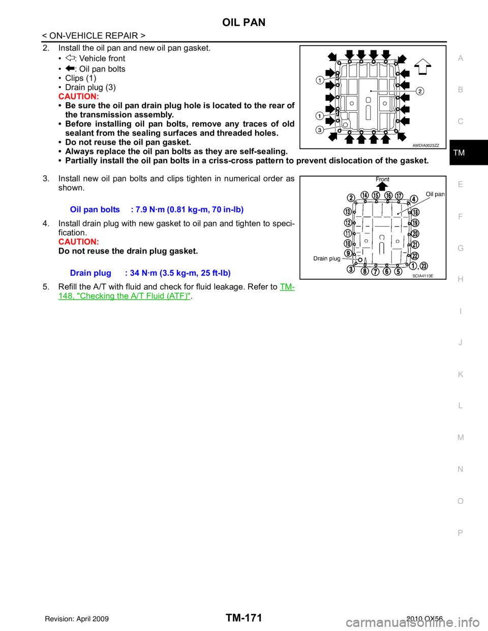
2. Install the oil pan and new oil pan gasket. • : Vehicle front
• : Oil pan bolts
• Clips (1)
• Drain plug (3)
CAUTION:
• Be sure the oil pan drain plug hole is located to the rear ofthe transmission assembly.
• Before installing oil pan bolts, remove any traces of old sealant from the sealing su rfaces and threaded holes.
• Do not reuse the oil pan gasket.
• Always replace the oil pan bolts as they are self-sealing.
• Partially install the oil pan bo lts in a criss-cross pattern to prevent dislocation of the gasket.
3. Install new oil pan bolts and clips tighten in numerical order as shown.
4. Install drain plug with new gasket to oil pan and tighten to speci- fication.
CAUTION:
Do not reuse the drain plug gasket.
5. Refill the A/T with fluid and check for fluid leakage. Refer to TM-
148, "Checking the A/T Fluid (ATF)".
AWDIA0023ZZ
Oil pan bolts : 7.9 N·m (0.81 kg-m, 70 in-lb)
Drain plug : 34 N·m (3.5 kg-m, 25 ft-lb)
SCIA4113E
Revision: April 20092010 QX56
Page 3867 of 4210
TM-172
< ON-VEHICLE REPAIR >
CONTROL VALVE WITH TCM
CONTROL VALVE WITH TCM
Control Valve with TCM and A/T Fluid Temperature Sensor 2 and PlugINFOID:0000000005148741
COMPONENTS
CONTROL VALVE WITH TCM REMOVAL AND INSTALLATION
Removal
1. Disconnect negative battery terminal.
2. Drain A/T fluid. Refer to TM-150, "
Changing the A/T Fluid (ATF)".
3. Disconnect A/T assembly harness connector.
1. Transmission 2. Snap ring3. Sub-harness
4. Control valve with TCM 5. Bracket 6. A/T fluid temperature sensor 2
7. Oil pan gasket 8. Brackets9. Oil pan bolt
10. Oil pan 11. Magnet12. Drain plug
13. Drain plug gasket 14. Terminal cord assembly 15. O-ring
16. O-ring 17. Plug
A/T fluid temperature sensor 2 (A) can be changed to plug (B), depending on vehicles.
JSDIA1314GB
Revision: April 20092010 QX56
Page 3869 of 4210
TM-174
< ON-VEHICLE REPAIR >
CONTROL VALVE WITH TCM
10. Remove bolts (A), (B) and (C) from control valve with TCM.• : Front
11. Remove control valve with TCM from transmission case. CAUTION:
When removing, be careful with the manual valve notch and
manual plate height. Remove it vertically.
12. Remove the A/T fluid temperature sensor 2 or plug as shown below.
a. A/T fluid temperature sensor 2
i. Remove A/T fluid temperature sensor 2 with bracket from con- trol valve with TCM.
ii. Remove bracket from A/T fluid temperature sensor 2.
b. Plug
Bolt symbol Length mm (in) Number of bolts
A 42 (1.65) 5
B 55 (2.17) 6
C 40 (1.57) 1
SCIA8074E
SCIA5142E
SCIA5253E
SCIA5264E
Revision: April 20092010 QX56
Page 3871 of 4210
TM-176
< ON-VEHICLE REPAIR >
CONTROL VALVE WITH TCM
15. Remove A/T assembly harness connector from control valvewith TCM using suitable tool.
16. Disconnect TCM connector (1) and transmission range switch connector (2).
CAUTION:
Do not damage connectors.
Installation
CAUTION:
• If the A/T fluid temperature sensor 2 has flaws, replace it with a plug.
• After completing installa tion, check A/T fluid leakage and fluid level. Refer to TM-148, "
Checking the
A/T Fluid (ATF)".
1. Connect TCM connector (1) and transmission range switch con- nector (2).
2. Install A/T assembly harness connector to control valve with TCM.
SCIA5448E
JSDIA1317ZZ
JSDIA1317ZZ
SCIA5450E
Revision: April 20092010 QX56