Page 3902 of 4210
DISASSEMBLYTM-207
< DISASSEMBLY AND ASSEMBLY >
CEF
G H
I
J
K L
M A
B
TM
N
O P
14. Loosen lock nut and remove band servo anchor end pin from transmission case.
15. Remove brake band from transmission case.
CAUTION:
• To prevent brake linings from cracking or peeling, do not
stretch the flexible band unnecessarily. When removing
the brake band, always secure it with a clip as shown.
• Check brake band facing for damage, cracks, wear or
burns.
16. Remove mid carrier assembly and rear carrier assembly as a unit.
SCIA6512E
SCIA2580E
SAT655
SCIA5017E
Revision: April 20092010 QX56
Page 3906 of 4210
DISASSEMBLYTM-211
< DISASSEMBLY AND ASSEMBLY >
CEF
G H
I
J
K L
M A
B
TM
N
O P
32. Disconnect output speed sensor connector (1). CAUTION:
Do not damage connector.
33. Straighten terminal clip ( ) to free output speed sensor har- ness.
34. Remove bolts (A), (B) and (C) from control valve with TCM. • : Front
35. Remove control valve with TCM from transmission case. CAUTION:
When removing, be careful with the manual valve notch and
manual plate height. Remove it vertically.
36. Remove the A/T fluid temperature sensor 2 or plug as shown below.
a. A/T fluid temperature sensor 2
JSDIA1319ZZ
JSDIA1320ZZ
Bolt symbol Length mm (in) Number of bolts
A 42 (1.65) 5
B 55 (2.17) 6
C 40 (1.57) 1
SCIA8077E
SCIA5260E
Revision: April 20092010 QX56
Page 3908 of 4210
DISASSEMBLYTM-213
< DISASSEMBLY AND ASSEMBLY >
CEF
G H
I
J
K L
M A
B
TM
N
O P
iii. RemoveO-ring (1) from plug (2).
37. Remove O-ring from A/T assembly harness connector.
38. Disconnect TCM connectors. CAUTION:
Do not damage connectors.
39. Remove A/T assembly harness connector from control valve with TCM using suitable tool.
40. Disconnect TCM connector (1) and transmission range switch connector (2).
CAUTION:
Do not damage connectors.
JSDIA1313ZZ
SCIA5155E
SCIA5447E
SCIA5448E
JSDIA1317ZZ
Revision: April 20092010 QX56
Page 3909 of 4210
TM-214
< DISASSEMBLY AND ASSEMBLY >
DISASSEMBLY
41. Remove rear extension assembly (2WD models) or adapter case assembly (4WD models) according tothe following procedures.
a. 2WD models
i. Remove bolts (1 brackets) for rear extension assembly and transmission case.
• Self-sealing bolts (2)
ii. Tap rear extension assembly with soft hammer.
iii. Remove rear extension assembly (with needle bearing) from transmission case.
WCIA0562E
SCIA5028E
SCIA5029E
Revision: April 20092010 QX56
Page 3910 of 4210
DISASSEMBLYTM-215
< DISASSEMBLY AND ASSEMBLY >
CEF
G H
I
J
K L
M A
B
TM
N
O P
b. 4WD models
i. Remove adapter case to transmission case bolts and terminal bracket (1).
• Self-sealing bolt (2)
ii. Tap adapter case assembly using suitable tool.
iii. Remove adapter case assembly (with needle bearing) from transmission case.
iv. Remove gasket from transmission case.
WCIA0563E
SCIA5201E
SCIA5186E
SCIA5231E
Revision: April 20092010 QX56
Page 3911 of 4210
TM-216
< DISASSEMBLY AND ASSEMBLY >
DISASSEMBLY
42. Remove bearing race from output shaft.
43. Remove output shaft from transmission case by rotating left andright.
44. Remove parking gear from output shaft.
45. Remove seal rings from output shaft.
46. Remove needle bearing from transmission case.
SCIA5245E
SCIA5030E
SCIA5247E
SCIA5209E
SCIA5031E
Revision: April 20092010 QX56
Page 3912 of 4210

DISASSEMBLYTM-217
< DISASSEMBLY AND ASSEMBLY >
CEF
G H
I
J
K L
M A
B
TM
N
O P
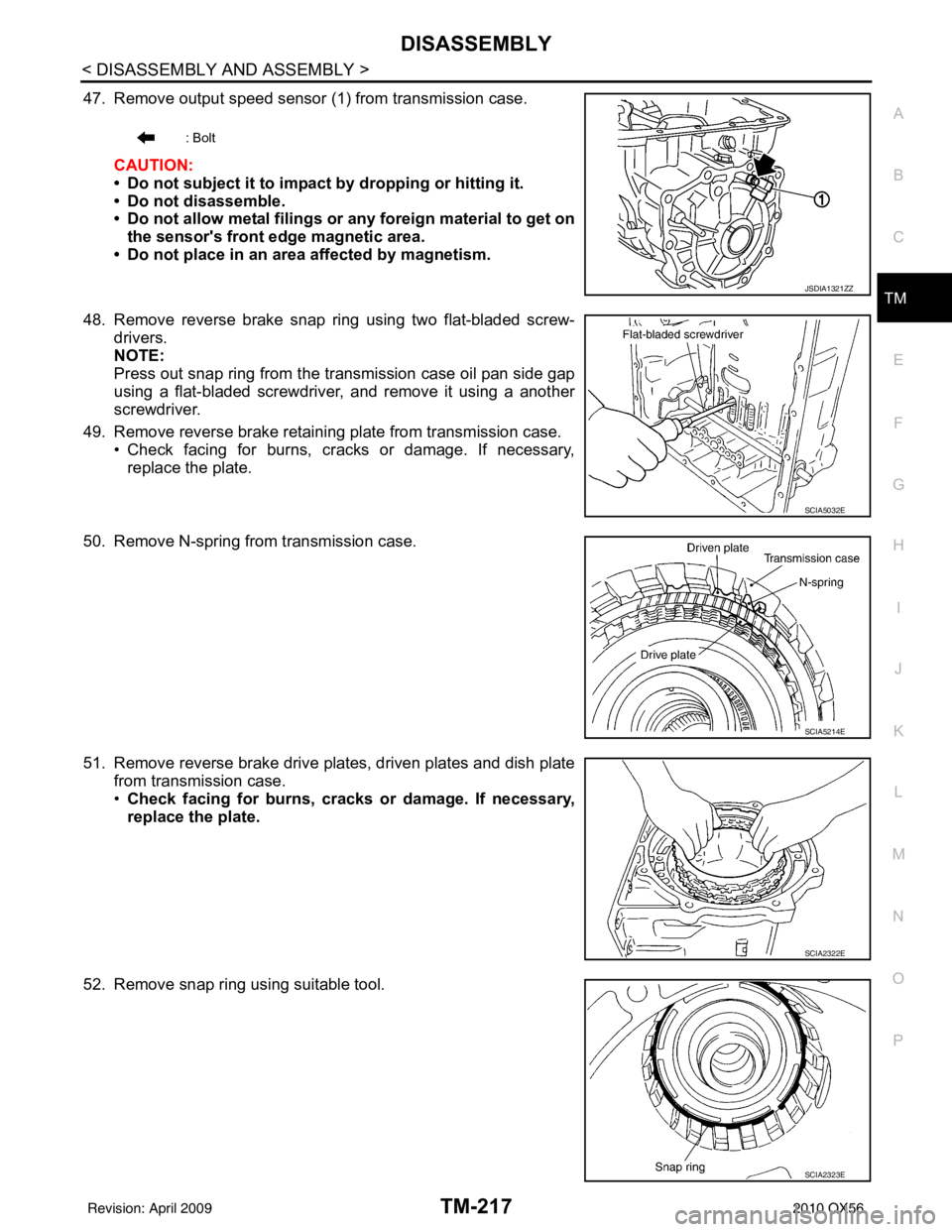
47. Remove output speed sensor (1) from transmission case.
CAUTION:
• Do not subject it to impact by dropping or hitting it.
• Do not disassemble.
• Do not allow metal filings or any foreign material to get onthe sensor's front edge magnetic area.
• Do not place in an area affected by magnetism.
48. Remove reverse brake snap ring using two flat-bladed screw- drivers.
NOTE:
Press out snap ring from the transmission case oil pan side gap
using a flat-bladed screwdriver, and remove it using a another
screwdriver.
49. Remove reverse brake retaining plate from transmission case. • Check facing for burns, cracks or damage. If necessary,
replace the plate.
50. Remove N-spring from transmission case.
51. Remove reverse brake drive plates, driven plates and dish plate from transmission case.
•Check facing for burns, cracks or damage. If necessary,
replace the plate.
52. Remove snap ring using suitable tool.
: Bolt
JSDIA1321ZZ
SCIA5032E
SCIA5214E
SCIA2322E
SCIA2323E
Revision: April 20092010 QX56
Page 3913 of 4210
TM-218
< DISASSEMBLY AND ASSEMBLY >
DISASSEMBLY
53. Remove spring retainer and return spring from transmissioncase.
54. Remove seal rings from drum support.
55. Remove needle bearing from drum support edge surface.
56. Remove reverse brake piston from transmission case using compressed air. Refer to TM-199, "
Oil Channel".
CAUTION:
Care should be taken not to ab ruptly blow air. It makes the
piston incline, and as a resu lt, it becomes hard to disas-
semble the pistons.
SCIA2324E
SCIA3333E
SCIA2796E
SCIA5047E
Revision: April 20092010 QX56